Abstract
A kineto-dynamic model of a cross-linkage air seat-suspension system is formulated to obtain relations for effective vertical suspension stiffness and damping characteristics. A two-stage optimization methodology is proposed to derive vehicle-specific optimal designs considering different classes of earthmoving vehicles. The results show that optimal air spring coordinates can yield nearly constant natural frequency during the deflection cycle, irrespective of the seated body mass and driver-selected seated height. Vehicle-specific optimal damping characteristics, identified in the second stage, provided substantial reductions in seat effective amplitude transmissibility (SEAT) and vibration dose values (VDV) for all classes of earthmoving vehicles considered in the study. The proposed kineto-dynamic model and optimization method could thus serve as an important tool for designing vehicle-specific suspension seats.
1. Introduction
Drivers of off-road vehicles are occupationally exposed to comprehensive magnitudes of low frequency whole-body vibration (WBV) and intermittent shocks. Apart from discomfort, fatigue and poor performance rate, WBV is associated with greater risks of low back pain and degenerative changes in spine among exposed drivers [1]. Such vehicles generally employ a seat-suspension to limit transmission of WBV to the seated driver. Vibration attenuation performance of seat-suspensions is strongly dependent upon magnitude and frequency contents of vehicle vibration, which may be characterized in three categories [2]: (i) suspension lock-up under low levels of vehicle vibration due to friction; (ii) attenuation or amplification under medium to high levels of continuous vibration leading to suspension travel within the permissible free travel depending upon the frequency contents of vehicle vibration and suspension design; and (iii) amplification of vibration and shock motions when suspension travel exceeds its free travel leading to impacts against elastic end-stops. Suspension designs within the last two categories pose conflicting requirements, particularly for the suspension damping.
The design of suspension seats also involves additional challenges associated with varying body mass and seated height. Variations in body mass may affect suspension natural frequency and thereby the vibration isolation performance [3]. A seat-suspension yields best performance when adjusted to mid-ride position so as permit maximum suspension travel in compression and rebound. Effective suspension stiffness, especially for air suspensions, and the permissible suspension travel, however, are affected by driver-selected seat height, which may cause impacts with motion limiting stops. A number of studies have identified optimal designs to address conflicting requirements for shock and vibration attenuation [4]. A number of semi-active and active seat-suspensions have also been proposed for achieving improved performance under varying excitations and body mass [5, 6].
The aforementioned studies on passive, semi-active and active seat-suspension systems have invariably employed equivalent vertical suspension stiffness and damping, while neglecting contributions due to suspension kinematics. The vast majority of the suspensions employ a cross-linkage mechanism with rollers to ensure pure vertical motion of the seat. The orientations of the air/mechanical spring and damper, generally attached to the cross links, thus vary considerably during a vibration cycle, which lead to nonlinear variations in effective stiffness and damping with the nature of base vibration. Furthermore, the effects of motion limiting stops within the suspension, variations in the body mass as well suspension height, and friction due to rollers are generally, which are known to strongly alter the suspension performance.
In this paper, a kineto-dynamic model of a seat-suspension system comprising an air spring and a hydraulic damper within a cross-linkage mechanism is formulated. The model is subsequently used to identify optimal coordinates of the air spring attachments and optimal damping requirements for vehicle-specific suspension seat designs.
2. Kineto-dynamic model formulations
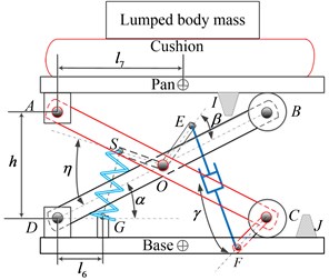
Fig. 1(a) illustrates planar representation of a seat-suspension-occupant system comprising an air spring and a hydraulic damper with two pairs of cross links of length , AC and BD. Links AC and BD are pinned to seat pan and base at A and D, respectively, and supported on guiding rollers at B and C, constrained along the horizontal direction. The two cross links are also attached at O via a pin joint (AO ; OC ). Suspension travel in extension and compression is limited by two elastic end-stops, I and J, respectively. The air-spring is attached to the cross links via arm OS (), while the hydraulic damper is mounted between F and E via arms CF () and OE (), respectively, attached to the cross-links. Table 1 summarizes the geometric and suspension parameters shown in Fig. 1, and is mid-ride height. Damper is modeled using two-stage properties, where and are low-speed damping constants in compression and rebound, and and are respective high-speed coefficients, while transitions between low- and high-speed damping occur at and . Nominal suspension considered in the study employed single-stage damping in compression [2]. The cushion is modeled using equivalent linear stiffness and damping . The force developed by air spring along its axis is derived from the air pressure assuming polytropic gas process, such that: , where and are pressure volume of air at equilibrium position, is effective area, is spring deflection along its axis and is polytropic constant.
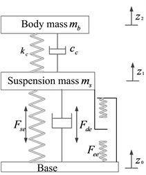
Fig. 1a) Kineto dynamic and b) equivalent vertical dynamic models of seat-suspension-occupant system
a)
b)
Suspension seats are invariably modeled using equivalent vertical properties, as shown in Fig. 1(b) [2]. Kinematics of the cross-links together with inclinations of air spring and damper, however, yield highly nonlinear variations in vertical spring and damping forces during a deflection cycle. In the model, the seated body is represented by a rigid mass , since the contributions of seated body biodynamics are known to be small for low natural frequency suspensions. The seat pan is denoted by a rigid mass , while end-stops are modeled as clearance springs with effective vertical end-stops forces as . The equations of motion of the two-DOF seat-occupant model, incorporating suspension kinematics, can be expressed as:
where and are displacements of suspension and the seated body masses, respectively, and is force developed by the cushion. The effective vertical forces due to air spring force , hydraulic damper force and end-stops force are derived considering the suspension kinematics, as:
where is force developed by damper along its axis and is horizontal force due to end-stop impacts. Above equations are solved to obtain vibration and shock isolation of the suspension under given excitation and body mass. The vibration isolation performance is evaluated in terms of seat effective amplitude transmissibility (SEAT), defined as ratio of overall frequency-weighted rms acceleration at the seat-occupant interface to that at the seat base [3]. The shock isolation performance is evaluated in terms of vibration dose value (VDV) ratio, ratio of VDV of seat mass vibration to that of the base vibration, while VDV is computed from:
where is frequency-weighted acceleration of the seat mass/base, which is obtained upon using frequency-weighting defined in ISO-2631/1 and is the simulation period.
Table 1Parameters of the seat-suspension used for model validation
Parameter | Value | Parameter | Value | Parameter | Value |
, m | 0.1792 | , m | 0.1792 | , deg | 31.02 |
, m | 0.0324 | , m | 0.0554 | , deg | 41.59 |
, m | 0.0472 | , m | 0.135 | Travel, mm | 140 |
, m | 0.2089 | (mid-ride), m | 0.160 | , deg | 79.88 |
, N/mm | 29.977 | , Ns/mm | 0.938 | , kg | 5 |
, kg | 77 | , kPa | 689.47 | , cm3 | 276.87 |
, cm2 | 28 | 1.38 | , m/s | 0.11563 | |
, Ns/mm | 4.83 | , Ns/mm | 6.13 | , Ns/mm | 2.45 |
3. Vehicle-specific seat-suspension design optimization
A two-stage optimization problem is formulated to seek vehicle-specific optimal designs considering suspension kinematics. In the first-stage, optimal spring coordinates are identified to obtain constant stiffness over the suspension stroke, and constant natural frequency for the range of body masses and suspension heights. The minimization problem is formulated to minimize maximum difference in effective stiffness over the entire suspension travel, such that:
where is the design vector related to air spring coordinates (Fig. 1). The above is solved subject to limit constraints: , and . Moreover, natural frequency (excluding the cushion) is permitted to vary in the 1.25 to 1.35 Hz range.
In the second stage, optimal suspension damping is identified to realize an improved compromise between SEAT and VDV ratios. It is evident that effective vertical mode damping is strongly dependent upon coordinates of the damper attachments, including damper orientations (, ), and lengths of arms OE () and CF (), apart from the low- and high-speed damping coefficients. A methodology is thus formulated to identify vehicle-specific optimal suspension damping under vibration spectra of different earthmoving vehicles (EM1, EM4, EM6, EM9) superimposed with a filtered shock pulse [7]. The minimization problem is formulated to reduce sum of SEAT and VDV ratio under each vehicular excitation, such that:
where is the design vector, and and are weighting constants, which are considered identical so as to equally emphasize the vibration and shock isolation. The above minimization problem is solved subject to constraints: with the exception of rebound transition velocity, limited to –0.06 m/s; and 0.06 m/s, while the static height of the suspension as taken at the mid-ride level, and the seated body mass is limited to that 50th percentile subject. Peak suspension deflection is further limited to free travel so as minimize the occurrence of end-stop impacts, such that: 70 mm.
4. Results and discussions
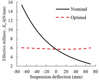
The optimal coordinates of air spring attachments were obtained as: 0.01 m, 0.05 m and 1.46 rad. Fig. 2(a) compares effective stiffness variations of optimal suspension with that of the nominal design. It is evident that the identified optimal spring coordinates can yield nearly constant effective stiffness over the entire suspension travel. The stiffness variations were further obtained for three different seat heights (±10 mm and ±20 mm from mid-position), and natural frequencies were estimated for three different seat loads (41.25, 56.25 and 67.5 kg), representing 75 % of 5th, 50th and 95th percentile body masses, while neglecting the effect of cushion. The results showed nearly constant natural frequency near 1.33 Hz, irrespective of the seat mass and the suspension height.
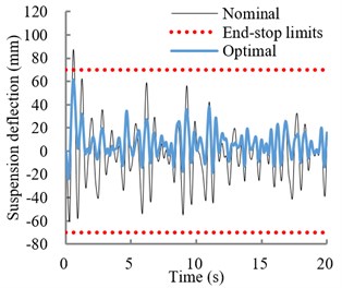
Fig. 2a) Variations in effective vertical stiffness of optimal and nominal suspensions; b) relative displacement response of the optimal and nominal suspension under EM1 excitation. (····Permissible suspension travel)
a)
b)
Table 2 summarizes optimal suspension damping parameters and coordinates of damper mounts for selected classes of vehicle vibrations superimposed with filtered shock pulses. Table also presents vibration and shock isolation performance of the optimal and nominal suspensions under selected excitations in terms of SEAT and VDV ratios. Results show substantially lower SEAT and VDV ratios of the optimal suspension compared to the nominal suspension. The VDV ratios are greater than SEAT values in all cases, which is due to presence of shock motion. As an example, Fig. 2(b) illustrates relative suspension deflection response under excitation (EM1). While the nominal suspension travel exceeds permissible free travel, the optimal suspension limits the deflection within the free travel and thereby eliminates end-stop impacts.
Table 2Optimal vehicle-specific optimal suspension damper parameters
Parameter | Optimal parameters for specific vehicle class excitation superimposed with filtered shock pulse | |||
EM1 | EM4 | EM6 | EM9 | |
, mm | 0.024 | 0.012 | 0.064 | 0.023 |
, mm | 0.025 | 0.024 | 0.016 | 0.046 |
, rad | 0.66 | 0.674 | 0.815 | 0.258 |
, rad | 0.789 | 0.71 | 0.142 | 0.255 |
, Ns/m | 9.01 | 10.01 | 2.32 | 5.78 |
, Ns/m | 4.23 | 2.3 | 1.54 | 4.21 |
, Ns/m | 2.19 | 6.5 | 3.39 | 3.63 |
, Ns/m | 1.23 | 3.4 | 3.23 | 2.15 |
, m/s | 0.05 | 0.033 | 0.02 | 0.01 |
, m/s | 0.055 | 0.035 | 0.015 | 0.015 |
SEAT | 0.46 | 0.56 | 0.30 | 0.18 |
VDV ratio | 0.62 | 0.72 | 0.51 | 0.32 |
Nominal suspension | ||||
SEAT | 1.20 | 1.23 | 0.33 | 0.43 |
VDV ratio | 1.31 | 1.50 | 0.56 | 0.55 |
5. Conclusions
Kinematics of the cross-linkage contributes to considerable variations in effective vertical spring rate and damping characteristics of the seat-suspension system during a deflection cycle. Variations in driver-selected seat height also yield considerable changes in suspension stiffness and thus the natural frequency. Optimal coordinates of air spring mounting could yield nearly constant stiffness and natural frequency over the entire suspension travel, irrespective of suspension height and seated body mass. A good compromise between the shock and vibration isolation performance can be achieved via optimal vehicle vibration-specific damping characteristics and its coordinates/orientation. Such a vehicle-specific optimal design could yield substantial reductions in SEAT and VDV ratio responses.
References
-
Burstrom L., Nilsson T., Wahlstrom J. Whole-body vibration and the risk of low back pain and sciatica: a systematic review and meta-analysis. International Archives of Occupational and Environmental Health, Vol. 88, Issue 4, 2015, p. 403-418.
-
Rakheja S., Boileau P.-É., Wang Z. Performance analysis of suspension seats under high magnitude vibration excitations. Part 1: model development and vibration. Journal of Low Frequency Noise, Vibration and Active Control, Vol. 22, Issue 4, 2003, p. 225-252.
-
Ma X. Q., Rakheja S., Su C.-Y. Damping requirement of a suspension seat subject to low frequency vehicle vibration and shock. International Journal of Vehicle Design, Vol. 47, Issues 1-4, 2008, p. 133-156.
-
Duke M., Goss G. Investigation of tractor driver seat performance with non-linear stiffness and on-off damper. Biosystems Engineering, Vol. 96, Issue 4, 2007, p. 477-486.
-
Wu X., Griffin M. J. A semi-active control policy to reduce the occurrence and severity of end-stop impacts in a suspension seat with an electrorheological fluid damper. Journal of Sound and Vibration, Vol. 203, Issue 5, 1997, p. 781-793.
-
McManus S. J., St Clair K. A., Boileau P. É. Evaluation of vibration and shock attenuation performance of a suspension seat with a semi-active magnetorheological fluid damper. Journal of Sound and Vibration, Vol. 253, Issue 1, 2002, p. 313-327.
-
Earth-Moving Machinery – Laboratory Evaluation of Operator Seat Vibration. International Standard, ISO 7096, 2000.
About this article

