Abstract
Hydraulic mounts can provide a better vibration attenuation performance than elastomeric mounts especially in the low frequency range. However, it is incapable of providing a response-dependent damper for the mount system to improve the ride comfort. In this study, a semi-active hydraulic cab mount (SHM) with control optimization was designed to improve ride comfort for the heavy vibratory roller. And a 7-DOF non-linear dynamic model of the vehicle was established for evaluation of the performance of hydraulic cab mounts based on different control optimization algorithms. To simulate roughness height the ISO level D road surface and deformed soil model were employed under the compaction work condition. The optimization study for two performance objectives as measured by responses of the vertical driver’s seat and cab pitch angle was carried out. It was shown that the SHM optimized by the fuzzy logic and proportional, integral, derivative controller methods (FLC-PID) giving best optimum values of the objective vector as compare to by multi-objective genetic algorithm (MOGA) and PID controller based on genetic algorithm (GA-PID).
1. Introduction
The cab isolation mounts performance of the vibratory roller is an important factor affecting the reliability of the roller, the comfort of operation, the noise level and the service life of the components. Therefore, improving the performance of the vibration isolation mounts system of the vibratory roller has an important role in improving the performance of the vibratory roller.
The design parameters of cab rubber mounts on the single drum vibratory roller ride comfort was analyzed by Ario Kordestani et al. [1]. Vibration analysis and improve the cab rubber mounts of vibratory roller via three cab’s isolation mounts including rubber, hydraulic, and pneumatic mounts to increase the ride comfort was studied [2]. The research results show that vibratory roller’s ride comfort is significantly increased by the hydraulic mounts (HM). Whereas, the ride comfort of the cab is still poor in condition of the vehicle moves.
In addition, the HM was also studied and applied for engine isolation system [3, 4], and semi-active hydraulic engine mounts were developed by Min Wang et al. [5]. In order to improve the harshness of construction equipment and industrial vehicles, the HM were used for cab mounts [6, 7]. The low frequency performance of vibratory roller cab with HM was studied [2]. However, this study only considers the passive cab isolation mounts. Nowadays, the control optimization methods such as multi-objective optimization [8], FLC-PID control [9], FLC-Hinf, MR Fluid damper and Skyhook-NFLC control [10, 11] are applied to adjust the damping coefficient for the semi-active suspension system or active suspension system of vehicles and seat. It was shown that mounts with control optimization can significantly enhance the ride comfort compared with the passive.
In this study, a non-linear dynamic model of the vibratory roller cab with the HM [2] is established based on Matlab/Simulink software. The control optimization methods as the multi-objective genetic algorithm, GA-PID controller, and FLC-PID controller are applied to optimize and control the cab hydraulic mounts under different operation conditions.
2. Materials and methods
2.1. Vibratory roller model
As shown in Fig. 1. The non-linear dynamic model of a single drum vibratory roller with 7-DOF is developed. , , , and represent the vertical displacements of the seat, the cab, the frame-front, the frame-rear and roller drum, respectively. , represent the angular displacements of the cab and the frame-rear; , , , and are the mass of the driver’s seat, cab, frame-front, frame-rear and roller drum, respectively; represent the semi-active damping force of hydraulic mounts. , , and represent the dynamic reaction forces in the vertical direction of seat suspension, cab mounts, roller drum mount and tire, respectively; and are the excitations of the road surface. is the distances of the vibratory roller, ( 1, 2; 1, 2, ..., 8). The equation of the dynamic reaction force of driver’s seat suspension is given by:
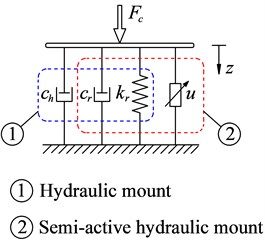
The equations of the dynamic reaction forces of cab isolation mounts in Fig. 1(b) are given by:
with:
where is the damping force of HM; , represent the stiffness coefficients and , represent damping coefficients of seat suspension and the rubber of HM, respectively.
Fig. 1Vibratory roller dynamic model
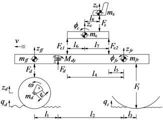
a) 7-DOF dynamic model
b) Model of cab mount
The relative displacements and velocities of HM are given by:
The force equations of the roller drum () and the tire () are derived in Section 3. The general dynamic differential equation for the vibratory roller is given as follow:
2.2. The vibration excitations of the vehicle dynamic model
In this study, the elastoplastic soil ground model of Adam D. and Kopf. F. [13] is chosen to establish the drum-deformed soil contact relation. In a cycle of the drum-deformed soil contact, there exist two or more often three distinct phases. The specific expression of motion can be referred to our previously published literature [2].
3. The control optimization methods
3.1. The optimal hydraulic mounts (OHM) based on the genetic algorithm
Multi-objective genetic algorithms (GA) are optimization method based on principles of natural selection. GA is defined as find a vector of decision variables satisfying constraints to give admissible to all objective functions [8], it can be written as:
Find the vector to optimize:
Subject to 0, 1 to ; 0, 1 to .
is objective functions, is inequality constraints, is equality constraints. According to the algorithm of GA [14], the structure flowchart of a genetic algorithm is shown in Fig. 2(a):
where is the weight r.m.s. acceleration responses of the driver’s seat and is the weight r.m.s. acceleration responses of the cab pitch angle.
3.2. Design of PID controller for SHM optimized by genetic algorithm (SHM with GA-PID)
The proportional integral derivate (PID) controller is wide used in industrial process control as a result of simple structure and robust performance. The transfer function of PID can be written by:
where , and are the proportional, integral and derivative parameters, respectively.
The choose of PID parameters is significant effect the performance of PID controller [15], therefore, GA and fuzzy logic control rules are applied to calculate the optimal proportionality factors, respectively , and as follows:
where the variable ranges of PID’s parameters are ; subscript denotes , and , respectively:
In order to find the optimal proportionality factors of , the variable ranges in Eq. (10) are also chosen optimally based on two objective functions in Eq. (7).
3.3. Design of PID controller for SHM based on fuzzy logic control rules (SHM with FLC-PID)
In this study, the relative displacement and relative velocity in Eq. (4), Eq. (5) of the cab isolation mount are considered as two input variables and they are denoted by E and EC, while the proportionality factors , , and are the output values, and the FLC-PID controller model shows in Fig. 2(b). The input and output linguistic variables are defined as positive big (PB), positive small (PS), zero (ZO), negative small (NS) and negative big (NB). The membership functions described by fuzzy set is the Triangular function and their values in the range of 0 and 1, both input and output values are in the [–3, 3] range.
Fig. 2The optimal control model
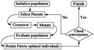
a) The flowchart of GA
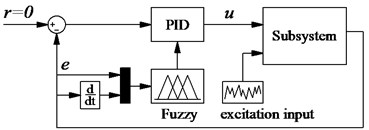
b) The FLC-PID controller
Table 1The fuzzy control rules
E | |||||||||||||||
EC | NB | NS | ZO | PS | PB | NB | NS | ZO | PS | PB | NB | NS | ZO | PS | PB |
NB | PB | PB | PS | ZO | ZO | NB | NB | NS | NS | ZO | PS | PS | ZO | ZO | PB |
NS | PB | PS | PS | ZO | NS | NB | NS | NS | ZO | ZO | NB | NS | NS | ZO | PS |
ZO | PS | PS | ZO | NS | NS | NS | NS | ZO | PS | PS | NB | NB | NS | ZO | PS |
PS | PS | ZO | NS | NS | NB | ZO | ZO | PS | PS | PB | NB | NS | NS | ZO | PS |
PB | ZO | ZO | NS | NB | NB | ZO | NS | NS | NB | PB | PS | ZO | ZO | ZO | PB |
In this fuzzy controller, there are up to 25 rules, shown in Table 1, has the following expression:
1. if E = NB and EC = NB then PB, NB and PS;
2. if E = NB and EC = NS then PB, NB and NB;
25. if E = PB and EC = PB then NB, PB and PB.
4. Simulation analysis
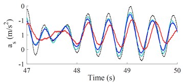
The weight r.m.s. acceleration value () and parameters of a vibratory roller in the reference [2] are used to evaluate the results. The results of the seat and cab pitch angle are shown in Fig. 3(a) and 3(b). It is shown that the and values with the control optimization methods reduced vibration and improved the cab’s ride comfort are very obvious. Besides, both and of SHM with FLC-PID also decreased compared with OHM and SHM with GA-PID.
Fig. 3The accelerations of seat and cab pitch angle
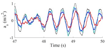
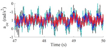
a) Low-frequency excitation of the drum (28 Hz)
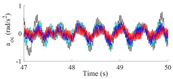
b) High-frequency excitation of the drum (35 Hz)

Table 2Performance of different mounts when vehicle compacts and moves
Values | HM | OHM | GA-PID | FLC-PID | FLC-PID versus HM | |
28 Hz | (m/s2) | 0.51 | 0.45 | 0.40 | 0.36 | 29.41 % |
(rad/s2) | 0.95 | 0.83 | 0.68 | 0.51 | 46.32 % | |
35 Hz | (m/s2) | 0.48 | 0.42 | 0.38 | 0.32 | 33.33 % |
(rad/s2) | 0.88 | 0.72 | 0.63 | 0.43 | 51.14 % | |
Table 2 shows that the and values with control optimization methods are all decreased compared with hydraulic mounts. When semi-active hydraulic cab mounts are controlled with the FLC-PID controller, the control results show that the and values are greatly reduced by 29.41 % and 46.32 % when vibrating drum compacts at low-frequency excitation and reduced by 33.33 % and 51.14 % at high-frequency excitation. Moreover, the study results also show that and values are significantly reduced when vibrating drum compacts at high-frequency excitation, it implies that the cab ride comfort is better when vibrating drum compacts at high-frequency excitation.
5. Conclusions
It was shown that the SHM optimized by the fuzzy logic and proportional, integral, derivative controller methods (FLC-PID) giving best optimum values of the objective vector as compare to by multi-objective genetic algorithm (MOGA) and PID controller based on genetic algorithm (GA-PID). Under the working condition of compaction, and values of SHM with FLC-PID significantly decreased by 29.41 % and 46.32 % at low-frequency excitation 28 Hz and reduced by 33.33 % and 51.14 % at high-frequency excitation 35 Hz.
References
-
Ario Kordestani, Subhash Rakheja, et al. Analysis of ride vibration environment of soil compactors. SAE International Journal of Commercial Vehicles, Vol. 3, Issue 1, 2010, p. 259-272.
-
Vanliem N., Jianrun Z., et al. Vibration analysis and modeling of an off-road vibratory roller equipped with three different cab’s isolation mounts. Shock and Vibration, Vol. 2018, 2018, p. 8527574.
-
Tikani R., Vahdati et al. N. A new hydraulic engine mount design without the peak frequency. Journal of Vibration and Control, Vol. 17, Issue 11, 2010, p. 1644-1656.
-
Hormoz Marzbani, Reza Jazar N., et al. Hydraulic engine mounts: a survey. Journal of Vibration and Control, Vol. 20, Issue 10, 2010, p. 1439-1463.
-
Min Wang, et al. A novel design of semi-active hydraulic mount with wide-band tunable notch frequency. Journal of Vibration and Control, Vol. 333, 2014, p. 2196-2211.
-
Kuzukawa M., Tanaka T. Vibration Dampening Device with an Elastic Body and Viscous Liquid. US Patent No. 5707048, 1998.
-
Lee P., Vogt J., Han S. Application of hydraulic body mounts to reduce the freeway hop shake of pickup truck. SAE Technical Paper Series 2009-01-2126, 2009.
-
Nariman-Zadeh N., et al. Pareto optimization of a five-degree of freedom vehicle vibration model using a MUGA. Engineering Applications of Artificial Intelligence, Vol. 23, 2010, p. 543-551.
-
Pekgökgöz R. K., et al. Active suspension of cars using fuzzy logic controller optimized by genetic algorithm. International Journal of Engineering and Applied Science, Vol. 2, Issue 4, 2010, p. 27-37.
-
Herrán Félix L.-C., Mehdi D., Ortizc Rodríguez De J.-J., et al. Hinfcontrol of a suspension with a magnetorheological damper. International Journal of Control, Vol. 85, Issue 8, 2012, p. 1366-5820.
-
Sy Dzung Nguyen, et al. Part 2: An application to semi-active vehicle seat-suspension system. Mechanical Systems and Signal Processing, Vol. 450, Issues 56-57, 2015, p. 288-301.
-
Mechanical Vibration-Road Surface Profiles – Reporting of Measured Data. ISO 8068, 1995.
-
Adam D., Kopf F. Theoretical analysis of dynamically loaded soils. European Workshop Compaction of Soils and Granular Materials, 2000, p. 207-220.
-
Jhon Crews H., et al. Multi-objective control optimization for semi-active vehicle suspensions. Journal of Sound and Vibration, Vol. 330, 2011, p. 5502-5516.
-
Zulfat H., et al. Application of self-tuning fuzzy PID controller on industrial hydraulic actuator using system identification approach. Journal on Smart Sensing and Intelligent Systems, Vol. 2, Issue 2, 2009, p. 246-261.
Cited by
About this article

This work is funded by Science and Technology Support Planning of Jiangsu Province (No. BE201433), Science and Technology Achievement Transformation Project of Nanjing (No. 201701213) and Talent Introduction Fund Project of Hubei Polytechnic University (Nos. 17xjz03R, 19xjk17R).
