Abstract
Heavy truck cabin ride comfort is studied, the evaluation method of the root-mean-square (r.m.s) acceleration of the vertical driver’s seat, the cab pitch and roll of heavy truck is presented, the random road roughness model is used for excitation. In this paper, a 3-D dynamic model with 13 DOF is established. Fuzzy logic controller is applied to control the cab’s isolation system of heavy truck, and the program is developed based on Matlab/Simulink software to simulate and calculate the r.m.s acceleration of the vertical driver’s seat, the cab pitch angle and roll angle under different road surface conditions. The obtained results showed that the semi-active cab’s isolation system is compared with the passive cab’s isolation system can reduce vibration and improve heavy truck ride comfort. Especially, on the ISO level B road at vehicle speed of 72 km/h, the r.m.s acceleration of the vertical driver's seat, cab pitch and roll angle are greatly reduced by 36.5 %, 10.8 % and 25 % respectively.
1. Introduction
Nowadays the market of heavy truck was competing very fierce and the features of heavy truck were claimed higher. One of the most important requirements of heavy truck is to improve heavy truck ride comfort and road friendless. Thus, in order to solve these problems, the heavy truck dynamic parameters as well as vehicle isolation systems were considered by some authors: Xu Zhongming et al. [1] applied a half-vehicle dynamic model analysis and research on improving the ride comfort of cab for heavy-duty, while Li Pengfei et al. [2] established a half-vehicle dynamic model to simulate and optimal the cab’s mounts to reduce the vertical vibration of the driver’s seat. Chen Jing et al. [3] used simulation experimental design the cab’s isolation system of heavy commercial vehicle and optimization. Zhang Junfeng et al. [4] studied a multi-body dynamic model for the cab’s isolation system, and the objective functions to be reduced the r.m.s acceleration of the vertical driver's seat and cab pitch angle. M. J. Mahmoodabadi et al. [5] used Genetic Algorithm for Pareto optimal design for a half-vehicle model to improve the ride comfort. In a half-heavy truck model is used for researches. Most of the mentioned works above focused on studying ride comfort by optimal design cab’s parameters and vehicle.
In recent years, heavy truck passive suspension system almost is studied and improved by using air suspension system, active and semi-active suspension system in order to its capabilities of consuming less power, low cost and providing better ride quality. Many researchers have been published on active and semi-active suspension system for vehicles. Michele Ieluzzi et al. [6], a 5-axle heavy truck which half-truck model was established, used Adams/Matlab simulation technique to control parameters of suspension system of the tractor driver, which the goal is to improve the ride comfort and road friendliness. Georgios Tsampardoukas et al. [7] used a half-vehicle model with hybrid balance control of a magnetorheo logical truck suspension system, the results of research reduced the r.m.s truck heave acceleration and dynamic tire forces on the axles. Zhengchao Xie, et al. [8] established a half-heavy truck model with semi-active air suspension system, fuzzy logic control, PID and wheelbase preview combined to control damping forces, the heavy truck ride comfort also was the goal of research. All the results present above shown that the heave truck suspension system was controlled not only increased the vehicle ride comfort but also reduced road damage. However, the controlling cab’s isolation system as well as the effect of cab roll angle and the vehicle on the ride comfort was not yet considered in these studies, Therefore, the effect of heavy truck vibration on the ride comfort was not fully reflected either.
The driver’s seat and cab’s isolation systems of heavy truck also impact not small to improve the ride comfort as well as the driver’s health. Besides, the cab roll angle and heavy truck roll angle also impact big to heavy truck ride comfort. In this study, a 3-D dynamic model with 13 DOF of heavy truck is established, Matlab/Simulink software is used to simulate and calculate the objections under different road surface conditions. The fuzzy logic controller is applied to control cab’s isolation system. This major goal is to improve the driver's seat comfort as well as the heavy truck ride comfort.
2. Heavy truck dynamic model
In this article, a 3-D dynamic model with 13 degrees of freedom is showed in Fig. 1. It includes the driver seat, the cabin, the vehicle body and three axles of vehicle. The driver’s seat suspension is equipped with a steel spring and a viscous damper characterized by stiffness coefficient and damping coefficient ; the cabin isolations are equipped with steel springs and viscuos dampers characterized by stiffness coefficients and damping coefficients ; the vehicle isolation systems also are equipped with steel-leaf springs and viscous dampers characterized by stiffness coefficients and damping coefficients ; the stiffness of wheels are equipped by stiffness coefficients .
In Fig. 1 , , and are the vertical displacements at centre of gravity of driver’s seat, cab, vehicle and the axles; , , , and are angular displacements at centre of gravity of cab, vehicle body and the axles; , and are the sprung mass of driver’s seat, cabin and vehicle; are the unsprung mass of the axles; are control inputs to cab's isolation system, difined as actuator forces to produce the control forces; are the excitations of the road surface roughness; and are the distances of vehicle (1-4; 1-6; 1-8).
Based on heavy truck dynamic model and by applying Newton's law, the motion equations of the driver’s seat and cab are given as follow:
where and are the driver’s seat suspension deflection and its derivation, and are the cabin’s isolation deflection and its derivation. They are given by:
when 1-2 then 0 and 6; when 3~4 then 3 and 7; .
Fig. 13D dynamic model with semi-active cab’s isolation system
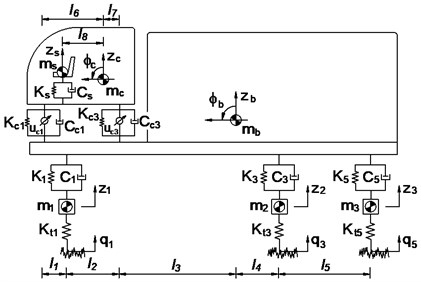
a) Side view of the heavy truck
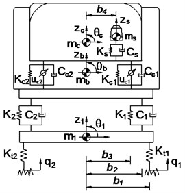
b) Front view of the heavy truck
3. The fuzzy logic controller (FLC)
In this article, four isolations of cabin should be controlled separately. Thus, four different fuzzy controllers should be designed. However, design process of these controllers were same, thus a specific fuzzy control was designed. The design of a fuzzy logic controller is as follows: The cabin’s isolation deflection (showed at Eq. (4)) and its derivation (showed at Eq. (5)) are the two input variables, while the variable damping force is output of the controller. The shape of membership function for the variables of in-output is the Triangular function and their values are between 0 and 1. The nine linguistic terms are defined as in Table 1 [8, 9].
Table 1Fuzzy linguistic values
Linguistic value | Description | |||
pvb | Positive very big | 0.1 | 0.5 | 2 |
pb | Positive big | 0.08 | 0.4 | 1.8 |
pm | Positive medium | 0.06 | 0.3 | 1.6 |
ps | Positive small | 0.04 | 0.2 | 1.4 |
ze | Zero | 0 | 0 | 0 |
ns | Negative small | –0.04 | –0.2 | –1.4 |
nm | Negative medium | –0.06 | –0.3 | –1.6 |
nb | Negative big | –0.08 | –0.4 | –1.8 |
nvb | Negative very big | –0.1 | –0.5 | –2 |
Table 2Rule base for fuzzy control
nvb | nb | nm | ns | ze | ps | pm | pb | pvb | ||
nvb | pvb | pvb | pvb | pvb | pvb | pm | ps | pvs | ze | |
nb | pvb | pb | pb | pb | pb | ps | pvs | ze | nvs | |
nm | pvb | pb | pm | pm | pm | pvs | ze | nvs | ns | |
ns | pvb | pb | pm | ps | ps | ze | nvs | ns | nm | |
ze | pvb | pb | pm | ps | ze | ns | nm | nb | nvb | |
ps | pm | ps | pvs | ze | ns | ns | nm | nb | nvb | |
pm | ps | pvs | ze | nvs | nm | nm | nm | nb | nvb | |
pb | pvs | ze | nvs | ns | nb | nb | nb | nb | nvb | |
pvb | ze | nvs | ns | nm | nvb | nvb | nvb | nvb | nvb | |
The if-then rules base is applied to describe according to expertise experiences and designer’s knowledge, there are at most 81 possible rules, the fuzzy rules are given in Table 2 and if – then rules base as following list:
(1) if nvb and nvb then pvb;
(2) if nb and nvb then pvb;
⁞
(81) if pvb and pvb then nvb.
Type of fuzzy inference system of Mamdani, which using the minimum function and the centroid method is selected in [9-11]. In this paper used the fuzzy inference of Mamdani for control system model.
4. Random excitation
The cab’s isolation system is considered under a random excitation which is established through an excitation source simulated by a vehicle moving on the actual road. The road profile of the road surface roughness can be determined by the experimental formula [12]:
where is the displacement power spectral densit () for the roughness of the road; 0.1 m-1 is a reference spatial frequency, 2 is the frequency index which determines the frequency configuration of the PSD of the road surface. Road surface roughness is assumed to be a zero-mean stationary Gaussian random process. It can be generated through an inverse Fourier transformation:
where is the number of intervals, with as the length of the road segment, is a random phase uniformly distributed from 0-2.
In this paper, accoding to the standard ISO 8068 [12]and the Chinese standard GB7031 [13], typical road surface roughness is established, and the simula-tion results are shown in Fig. 3.
Fig. 2Typical excitation of road surface roughness according to ISO 8068 [12]
![Typical excitation of road surface roughness according to ISO 8068 [12]](https://static-01.extrica.com/articles/17468/17468-img3.jpg)
5. Simulation results and analysis
In this work, the cab’s isolation system of heavy truck is simulated and controlled by fuzzy control under the random excitation of the road surface roughness. The objective functions of this research to be reduced the r.m.s acceleration of the driver seat heave, cabin pitch and roll angle accoding to the standard ISO 2631-1 [14] (Table 3), and the reference parameters of heavy truck in [15].
Table 3Comfort levels related to awz threshold values
/ (m.s-2) | Comfort level | / (m.s-2) | Comfort level |
Less than 0.315 | Not uncomfortable | 0.8 to 1.6 | Uncomfortable |
0.315 to 0.65 | A little uncomfortable | 1.25 to 2.5 | Very uncomfortable |
0.5 to 1.0 | Fairly uncomfortable | Greater than 2 | Extremely uncomfortable |
5.1. Control the cab’s isolation system
The fuzzy logic controller tool with simulink in Matlab sofware are used to simulate and control the cab's isolation system of heavy truck on ISO lever B road at vehicle speed of 72 km/h. The results of simulation are showed in Fig. 4, the vertical acceleration of driver’s seat, the accelerations of cabin pitch and roll angle are significantly reduced in comparison with the cab’s passive isolation system. In Table 4 showed that, the results of the r.m.s accelerations are significantly decreased by 36.5 %, 10.8 % and 25 % respectively. According to the standard ISO 2631-1 (Table 3), the driver felt a little uncomfortable ( 0.599 m/s2) with the cab's passive isolation system, when cab’s isolation system is controlled by fuzzy control then the driver felt not uncomfortable (0.380 m/s2).
Fig. 4 showed the control forces , , and for the cab’s isolation system. The maximum values of control forces and are approximation of 110 N, while the maximum values of control forces and are approximation of 120 N. Thus, the cheaper and smaller actuator forces for cab's semi-active isolation system will significantly increase the ride comfort in comparison with the cab's passive suspension system.
Fig. 3The accelerations of the driver’s seat and cab
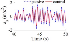
a) The vertical acceleration of driver’s seat
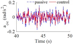
b) The acceleration of cabin pitch angle
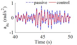
c) The acceleration of cabin roll angle
Fig. 4The control forces for the cab’s isolation system
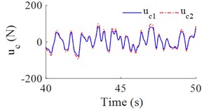
a) The control forces and
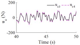
b) The control forces and
Table 4The r.m.s accelerations of driver’s seat and cab on ISO level B
(m/s2) | (rad/s2) | (rad/s2) | |
Passive | 0.599 | 0.046 | 0.255 |
Fuzzy control | 0.380 | 0.041 | 0.204 |
Percentage reduction (%) | 36.5 % | 10.8 % | 25 % |
Table 5The r.m.s acceleration of the driver’s seat on road surface roughness
(m/s2) | Typical excitation of road surface roughness | ||
Level A | Level C | Level D | |
Passive | 0.283 | 1.082 | 1.912 |
Fuzzy control | 0.170 | 0.749 | 1.456 |
Percentage reduction (%) | 39.9 % | 30.7 % | 23.8 % |
5.2. Simulation results on the different road surface roughness
In order to evaluate the ability of fuzzy logic controller, in this part, the heavy truck moving on other roads as ISO level A, ISO level C and ISO level D at vehicle speed of 72 km/h are simulated and analyzed.
Fig. 5(a), 5(c) showed that the results of the r.m.s accelerations of the vertical driver’s seat, cab pitch angle all are significantly reduced in comparison with cab’s passive isolation system. In Table 5 showed that, the results of the r.m.s acceleration of the driver’s seat are decreased by 39.9 %, 30.7 % and 23.8 % respectively on ISO level A, ISO level C and ISO level D. However, Fig. 5(b) showed that, the values of r.m.s acceleration of cab pitch angle were reduced very small in comparison with passive isolation system of cab, but these values are very small so that not affect to the ride comfort.
Fig. 5The r.m.s acceleration on other roads
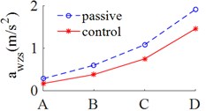
a) The vertical driver’s seat
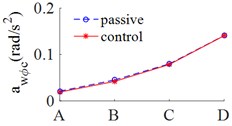
b) Cabin pitch angle
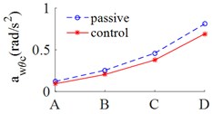
c) Cabin roll angle
6. Conclusions
In this research, the evaluation method of the weighted r.m.s acceleration responses of the vertical driver’s seat, cabin pitch and roll angle of heavy truck is presented. The fuzzy logic controller is applied to control the cab’s isolation system. The major conclusions that can be drawn from the evaluation results as follows: 1) The r.m.s acceleration of the vertical driver’s seat, the cab pitch and roll angle were significantly reduced by 36.5 %, 10,8 % and 25 % on ISO level B at vehicle speed of 72 km/h. 2) The r.m.s accelerations of the vertical driver's seat on ISO level A, ISO level C and ISO level D at vehicle speed of 72 km/h also were decreased by 39.9 %, 30.7 % and 23.8 %, thus, the ride comfort all was significantly improved.
References
-
Xu Zhongming, Zhang Zhifei, He Yansong Research on improving the ride comfort of cab for heavy-duty truck. China Mechanical Engineering, Vol. 15, Issue 17, 2004, p. 1584-1586.
-
Li Pengfei, Ma Li, He Tianming A simulation study on vibration isolation of cab mount s in a commercial vehicle. Automotive Engineering, Vol. 27, Issue 6, 2005, p. 741-743.
-
Chen Jing, Cao Xiaolin, Wang Dengfeng Matching and optimization of heavy commercial vehicle. Journal of Jilin University, Vol. 29, Issue 5, 2009, p. 1125-1127.
-
Zhang Junfeng, He Yansong, Yang Haiwei Modification of cab suspension system based on pitch angular acceleration. China Mechanical Engineering, Vol. 23, Issue 18, 2012, p. 2258-2262.
-
Mahmoodabadi M. J., Adljooy Safaie A., Bagheri A., Nariman-Zadeh N. A novel combination of Particle Swarm Optimization and Genetic Algorithm for Pareto optimal design of a five-degree of freedom vehicle vibration model. Applied Soft Computing, Vol. 13, 2013, p. 2577-2591.
-
Ieluzzi Michele, Turco Patrizio, Montiglio Mauro Development of a heavy truck semi-active suspension control. Control Engineering Practice. Vol. 14, Issue 3, 2006, p. 305-312.
-
Tsampardoukas Georgios, Stammers Charles W. Hybrid balance control of a magnetorheo logical truck suspension. Journal of Sound and Vibration, Vol. 317, 2008, p. 514-536.
-
Xie Zhengchao, Wong Pak Kin, Zhao Jing, Xu Tao, Wong Ka In, Wong Hang Cheong A Noise-insensitive semi-active air suspension for heavy-duty vehicles with an integrated fuzzy-wheelbase preview control. Mathematical Problems in Engineering, 2013, p. 1-13.
-
Qazi Abroon Jamal, de Silva Clarence W., Khan Afzal, Tahir Khan Muhammad Performance analysis of a semi-active suspension system with particle swarm optimization and fuzzy logic control, The Scientific World Journal, 2014.
-
Nguyen Sy Dzung, Nguyen Quoc Hung, Choi Seung-Bok A hybrid clustering based fuzzy structure for vibration control. Part 2: An application to semi-active vehicle seat-suspension system. Mechanical Systems and Signal Processing, Vols. 56-57, Issue 450, 2015, p. 288-301.
-
Mamdani E. H. Advances in the linguistic synthesis of fuzzy controllers. International Journal of Man-Machine Studies, Vol. 8, Issue 1, 1976, p. 669-678.
-
ISO 8068: Mechanical Vibration-Road Surface Profiles – Reporting of Measured Data. 1995.
-
GB7031. Vehicle Vibration – Describing Method for Road Surface Irregularity. 1986.
-
ISO 2631-1: Mechanical Vibration and Shock-Evaluation of Human Exposure to Whole Body Vibration – Part 1: General Requirements. 1997.
-
Li Bohao 3-D Dynamic Modeling and Simulation of a Multi-Degree of Freedom 3-Axle Rigid Truck with Trailing Arm Bogie Suspension. University of Wollongong, New South Wales, Australia, 2006.
About this article

