Abstract
This paper mainly studies a reverse engineering of material parameters through finite element optimization algorithm based on free modal test results, focusing on free modal test and establishment of finite element optimization model. The elastic modulus and density of the material can be solved by the finite element optimization algorithm to ensure the accuracy of the simulation results. When the accurate material parameters are obtained, the accuracy of abnormal sound simulation can be improved. It plays a guiding role in the development of vehicle BSR performance, so as to improve the ride comfort of the vehicle.
1. Introduction
In NVH simulation analysis, the elastic modulus and density of materials are very important to the accuracy of simulation results [1]. For the same material, the material parameters provided by different suppliers are not the same, which leads to great differences between the simulation results and the test results, which has no guiding significance for the development and design.
In order to obtain the elastic modulus and density of the material, first, actual modal frequency and shape can be obtained through the free modal test [2-5], and then the finite element optimization model is constructed, taking values of free modal test as the reference values, and the elastic modulus and density of the material can be solved. Finally, the elastic modulus and density obtained from the solution are used as the input for the modal simulation analysis, comparing with simulation results and the test results.
2. Free mode test
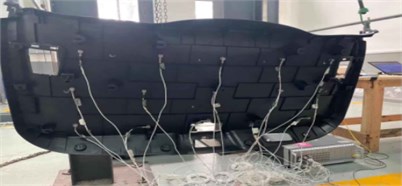
The sample used in this paper is the tailgate trim panel of an SUV, which is made of PP / PE and weighs 1.8 kg. The equipments for modal test are LMS Test. Lab, 15 unidirectional piezoelectric sensors, each weighing 4 g, a rubber hammer. Two points elastic suspension is used for the test sample, as shown in Fig. 1.
Fig. 1Free mode test
The free mode test results are shown in Table 1.
Table 1Mode test results
Modal orders | Frequency / Hz |
1 | 8.8 |
2 | 31.6 |
3 | 40.4 |
4 | 42.8 |
5 | 52.3 |
6 | 54.5 |
7 | 63.0 |
8 | 70.2 |
9 | 71.0 |
10 | 76.8 |
11 | 78.6 |
12 | 86.4 |
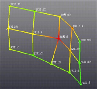
The first torsional mode and the first bending mode are shown in Figs. 2 and 3.
Fig. 2The first torsional mode
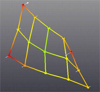
Fig. 3The first bending mode
3. Establish the finite element optimization model
3.1. Mesh the tailgate trim panel
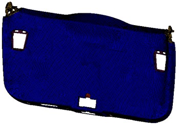
Import the tailgate trim panel into HyperMesh, switch to the Optistruct template, extract the middle plane and mesh the tailgate trim panel. The mesh adopts CQUAD4 & CTRIA3 element, and the average size of the mesh is 5 mm. The finite element model of the tailgate trim panel is shown in Fig. 4. The sensor used in the modal test is simulated by CONM2 element, and the position of the mass element is consistent with that in the modal test.
Fig. 4The trim panel of tailgate
4. Establish the finite element optimization model
The finite element optimization model is established in HyperMesh-Optistruct.
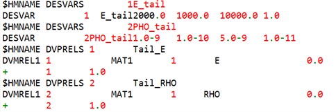
4.1. Setting optimization variables
For the content of this paper, the elastic modulus and density of the material should be set as the optimization variables. And associate the variable with the corresponding attribute. The variable setting and attribute association in HyperMesh-Optistruct are shown in Fig. 5.
Fig. 5The optimization variables
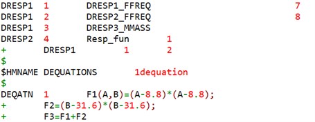
4.2. Setting the responses
This example needs to establish four responses, which are the first order modal frequency of the flexible body, the second order modal frequency of the flexible body, the total mass of the model and the functional response. The functional response is the square sum of the difference between the simulation results and the test results [6-8]. The test modal frequency of the first order flexible body is 8.8 Hz, and that of the second order flexible body is 31.6 Hz. The specific settings are shown in Fig. 6.
Fig. 6The optimization variables
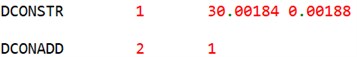
4.3. Setting the constraints
Since the actual mass of the sample is known, the total mass of the model is set as a constraint variable, and the total mass of the tailgate trim panel and sensor is 1860 g. In order to ensure the convergence of the optimization model, the total mass of the model is allowed to fluctuate in a small range, and the fluctuation range is 40 g. The constraint settings are shown in Fig. 7.
Fig. 7The optimization variables
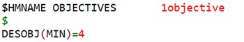
4.4. Setting the objectives
In order to improve the consistency between the optimization results and the test results, it is necessary to minimize the error between the simulation and the test. The optimization objective of this paper is to minimize the sum of squares of the differences between the simulation results and the test results, as shown in Fig. 8.
Fig. 8The objective
4.5. Solving the finite element optimization model
After the optimization model is established, it is submitted to Optistruct solver for solution, and the solution result is shown in Fig. 9.
Fig. 9The optimization results
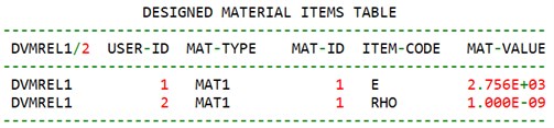
4.6. Comparative simulation and experiment
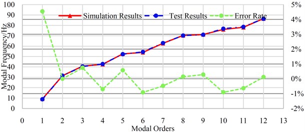
From the above optimization results, it can be seen that the elastic modulus of the tailgate trim panel of the SUV is 2756 MPa and the density is 1.0e-9t/mm3. Assign the value to the finite element model, carry out free modal analysis again, and compare the analysis results with the test results. The comparison results are shown in Table 2 and Fig. 10. The error rate defined here is the absolute error rate, that is, the simulation result minus the test result and then divided by the test result.
Table 2Mode benchmarking results
Modal orders | Simulation results | Test results | Error rate |
1 | 9.2 | 8.8 | 4.55 % |
2 | 31.6 | 31.6 | 0.00 % |
3 | 40.7 | 40.4 | 0.74 % |
4 | 42.5 | 42.8 | –0.70 % |
5 | 52.6 | 52.3 | 0.57 % |
6 | 54.0 | 54.5 | –0.92 % |
7 | 62.7 | 63.0 | –0.48 % |
8 | 70.3 | 70.2 | 0.14 % |
9 | 71.2 | 71.0 | 0.28 % |
10 | 76.1 | 76.8 | –0.91 % |
11 | 78.1 | 78.6 | –0.64 % |
12 | 86.5 | 86.4 | 0.12 % |
Fig. 10The modal benchmarking results
5. Conclusions
In this paper, the modal frequencies of tailgate trim panel is obtained by modal test, and the elastic modulus and density of the material are solved by the finite element optimization model, and the obtained elastic modulus and density are substituted into the finite element model for free modal analysis. Finally, the simulation values are compared with the test values, and the error of the first flexible body modal frequency is 4.55 % within 80 Hz. The error rate of the remainder is less than 1 %, which verifies the effectiveness of the method, and then can ensure the prediction accuracy of CAE simulation for NVH.
References
-
W. H. Yan, L. H. Huang, H. L. Liu, and J. Xing, “Overview of automobile door trim plastic fasteners,” Automotive Engineer, Vol. 10, pp. 53–58, 2017.
-
M. Xu, J. H. Zhang, Q. Wang, S. M. Wang, G. Q. Hu, and Q. R. Zhao, “Experimental modal comparative analysis and dynamic characteristic evaluation of body-in-white and trim body,” Journal of Machine Design, Vol. 31, No. 8, pp. 40–44, 2014, https://doi.org/10.13841/j.cnki.jxsj.2014.08.010
-
L. Huang, “Research on the modal test and simulation benchmarking analysis of BIW,” Automobile Applied Technology, Vol. 46, No. 14, pp. 84–86, 2021, https://doi.org/10.16638/j.cnki.1671-7988.2021.014.025
-
J. S. Diao, W. H. Liu, and Y. P. Yin, “Contrast of CAE and experimental analysis method for natural vibration characteristic of BIW,” Journal of Jinggangshan University, Vol. 40, No. 2, pp. 72–76, 2019.
-
J. T. Jin, Y. B. Zhang, T. Li, and W. Z. Lou, “Modal simulation and test calibration of mount bracket,” Automotive Engineer, Vol. 8, pp. 49–51, 2021.
-
S. B. Chen, X. W. Pan, and J. F. Liu, “Impact localization method based on the partial least squares regression fractal dimension,” Journal of Vibration and Shock, Vol. 40, No. 2, pp. 97–102, 2021, https://doi.org/10.13465/j.cnki.jvs.2021.02.013
-
J. D. Xu, “A Fast Otsu Image Segmentation Method Based on Least Square Fitting,” Journal of Changzhou University, Vol. 33, No. 1, pp. 70–76, 2021.
-
Y. Zhong et al., “Physicochemical properties, content, composition and partial least squares models of A. trifoliata seeds oil,” Food Chemistry, Vol. 12, p. 100131, Dec. 2021, https://doi.org/10.1016/j.fochx.2021.10013
Cited by
About this article

This research was financially supported by the consumer car driving and riding evaluation (011520) and the research on sound quality control method under transient operations of vehicle performance integration (NVHSKL-ZS-202101).
