Abstract
The flow-induced lateral vibration phenomenon of the terminal sensitive bullets (TSB) when it is dispersed by the airborne distributor is taken as the research background. Based on the Fluent, the flow around a rotating short cylindrical TSB ( < 1) is simulated and analyzed varying with relative rotation velocity at high Re number (1×10⁵ ≤ ≤ 3×10⁶). The simulation results show that the flow field structure of the short cylinder with two free ends is different from the symmetry of the short cylindrical flow field with one free end, and there is no horseshoe vortex. Compared to the long cylinder with double free ends, the of the short cylinder is more sensitive to the change of Re. With the increase of , the of the short cylinder decreases, and the value is between the infinite cylinder and the sphere in the non-critical region. When the short cylinder rotates at the angular velocity , the top vortex bends and deforms to a ‘C’ shape on the leeward side where the fluid is accelerated. Due to the periodic disturbance of the detector, the aerodynamic coefficient of the rotating TSB is periodically vibrated. In a single cycle, the waveform of the shows a ‘W’ shape, and the waveform of the is ‘M’.
1. Introduction
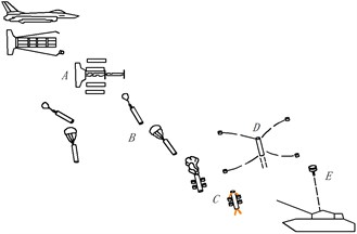
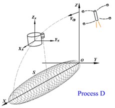
The short cylindrical terminal sensitive bullet (TSB) consists of a short cylindrical warhead and an external detector [1-3]. The working process is shown in Fig. 1, which is divided into five processes: ABCDE. According to the classical boundary layer theory [4], when the number is 70 < < 1×10⁶ and 3×10⁶ < , after the fluid flows through the cylinder, there will be a pair of counter-rotating vortices that alternately fall off the cylinder. In the D process, the bullet is thrown at a horizontal velocity while spun at a highly angular velocity around the cylindrical axis. Based on the design conditions, the Reynolds number is at 2×10⁵ ≤ ≤ 1×10⁶, which belongs to the low-drag subcritical region obtained by the classic cylinder flow test. It is highly likely that there is a regular Karman vortex in this region. When the vortex alternately falls off from the upper and lower boundary layers, it will act on the cyclically varying pulsation of the TSB to raise the drag, causing the short cylindrical bullet to vibrate. When the pulsation frequency of drag and lift is close to the natural frequency of the TSB, the structural vibration will be induced.
Fig. 1The working process of a short cylindrical TSB and its structure
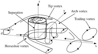
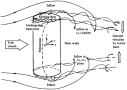
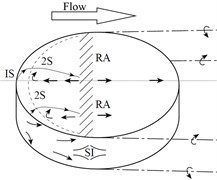
At present, most of the research work focuses on the flow around the infinite cylinder. However, most of the practical applications are finite cylinder with one free end (chimneys, cylindrical tall buildings, etc.) or two free ends (submarines, torpedoes, wheels [5], etc.). For a finite cylinder with one free end, the aspect ratio () of the cylinder becomes an important factor affecting the flow. Pattenden R. J. [6] and obtained the flow field topology around short cylinder ( = 1) with one free end shown in Fig. 2(a). And a turbulent horseshoe vortex is formed at the junction of the cylinder and mounting plate. There are relatively few studies on the flow of a finite cylinder with two free ends. In 1989, via the oil-film experiment, Zdravkovich [7] found that when the cylinder aspect ratio is 2 < < 8, a periodically falling vortex street can be observed. In 2000, Zdravkovich [8] conducted an experimental study of the flow around a short cylinder (0 ≤ ≤ 1). The results show that the drag coefficient and the aspect ratio satisfy the relation: , and the flow field topology of the short cylinder with two free ends is shown in Fig. 2(c). In 2008, Inoue and Osamu [9] used numerical simulation methods to study the flow around cylinder with two free ends at 0.5 < < 100 and 40 < < 300. The results show that the cylinder aspect ratio and Reynolds number have a great influence on the vortex shedding mode. And corresponding to different working conditions, five kinds of vortex shedding patterns were proposed. Prosser Daniel T. and Smith Marilyn J. [10, 11] used LES model and full-scale model flight tests to study the flow around the bluff body ( = 1, 2) at 1×10⁵ ≤ ≤ 1×10⁶. For the first time, the influence of angle of attack (0-90°) on the aerodynamic parameters of a short cylindrical bluff body is considered. In 2018, Wenjun Gao [12] used a numerical simulation method to study the flow pattern and flow field structure of the cylinder with two free ends. The result shows that there is no horseshoe vortex in the flow field. And a new relationship between the drag coefficient and the Reynolds number of the short cylinder ( = 1.5) with two free ends is proposed.
Fig. 2Topology structure of flow field. a) finite short cylinder (L/D = 1) with one free end (Pattenden); b) long cylinder with two free ends (L/D > 1); c) short cylinder with two free ends (L/D < 1).
a)
b)
c)
In this paper, the short cylindrical TSB is taken as the research object to study the flow field structure characteristics around the bullet during the initial stage of D process in Fig. 1. According to the structure characteristics of the TSB (consisting of a central short cylinder plus an external cube detector, the volume ratio of the detector to the center short cylinder is less than 0.025), the flow field structure around the bullet can be considered as a periodic small disturbance, caused by the detector, superimposed on the flow of the rotating short cylinder. At present, the research on the flow around the rotating cylinder is based on an infinite cylinder. And there is no research result on the flow around the rotating short cylinder ( < 1) with two free ends. First of all, the flow field structure characteristics of the rotating short cylinder with two free ends is analyzed through numerical simulation. The influence of length-to-radius ratio , number and relative rotation velocity on the flow field structure and aerodynamic coefficients around short cylinder with two free ends is studied. On this basis, the influence of the detector on the aerodynamic characteristics and flow field structure of the TSB is studied.
2. Computational models and method verification
2.1. Description of the simulation model and grid division
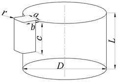
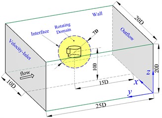
Sliding grid technology is used to simulate the rolling motion of short cylindrical TSB. The flow field geometry model and boundary conditions are shown in Fig. 3 (a). When the values are discrete, the entire flow field is divided into inner flow zone and far-field static zone. By giving a specific rotational speed to the inner flow zone, the rolling motion of the bullet body is achieved. The interface boundary is used to connect two zones, and an interpolation method is used to transfer the flow field information at the interface. The diameter of the cylinder in the center of the TSB is , and its length is . The detector is a quadratic prism of , and the outside edge has an inverted arc r. The far-field static zone is a 20D×20D×25D cuboid. The inner flow zone is a sphere with 7D diameter. The distance between the center of the sphere in the inner flow zone and the far-field exit of the downstream is 15D, and the distance from the other five boundaries is 10D. The upstream entrance of the far-field static zone adopts the velocity-inlet boundary, the downstream exit adopts the outflow boundary, and the other four planes and the surface of the bullet body adopt the non-slip wall boundary.
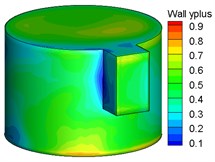
Fig. 3The numerical calculation model of TSB. a) Simulation model of flow field b) Inner and outer region of moving mesh c) y+ distribution of bullet
a)
b)
c)
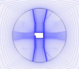
The hexahedral structure mesh is used to divide the entire flow field in the far-field static zone and the internal flow zone. The mesh quality is directly related to the accuracy of the solution results. And there is complicated three-dimensional shear separation flow in the boundary layer around the TSB and aerodynamic characteristics such as Magnus effect caused by rotation, so the number of grids in the internal flow zone accounts for more than 78 % of the total number of grids. The total number of flow field grids is 2.9 to 3 million, and the calculated flow field grid division results are shown in Fig. 3(b). In the internal flow zone, the bullet boundary layer is encrypted using an O-type topology. The thickness of the first layer of the wall is taken as 0.003 mm, and the growth rate of the thickness of the mesh extending from the wall surface to the outside is less than 1.2. Thus, < 1 on the surface of TSB, and its distribution cloud is shown in Fig. 3(c).
2.2. Numerical verification
Before analyzing the flow characteristic of the rotating short cylinder, the accuracy of the simulation model was verified by comparing with the experimental results of Zdravkovic. The flow pattern (as shown in Fig. 4) of short cylinder obtained from this paper is in good agreement with the experimental results shown in Fig. 2 (c). In the front of the double free end plane, reflux vortex and secondary separation are formed. On the side of the short cylinder, there is a clear separation line. Different from the flow field structure of short cylinder ( < 1) with one free end in Fig. 2(a), there is no horseshoe vortex for short cylinder with two free ends. Therefore, the flow field of a short cylinder with two free ends cannot simply be equal to the symmetry of the flow field for a short cylinder with one free end. As shown in Fig. 5, keeping the Reynolds number unchanged, the change law between and obtained in this paper is exactly the same as experimental results. Due to the existence of the supporting device in the experiment, the experimental data was slightly larger than the simulation results in general. It can be seen that this simulation model can be used to solve the flow problem of a short cylinder ( < 1) with two free ends.
Fig. 4Flow field structure of the short cylinder
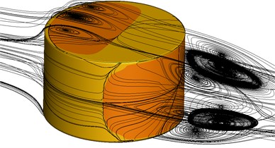
Fig. 5Comparison between present work and EXP [7, 8]
![Comparison between present work and EXP [7, 8]](https://static-01.extrica.com/articles/19912/19912-img11.jpg)
3. Results and discussion
3.1. The analysis of flow field characteristic
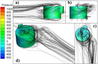
Fig. 6 shows the flow structure of rotating short cylinder at = 1.74×10⁵, where (a) is a front view, (b) is a top view, and (c) is a graphic model. Compared to the flow pattern of the non-rotating cylinder in Fig. 4, when = 1, the recirculating region of the free end and the leeward surface and the separation line of the side surface are all significantly deflected in the positive direction of . On the side where the fluid is accelerated, the streamline is spirally bent, causing the top vortex to deform into a ‘C’ shape. Fig. 7 shows the flow structure of a rotating short cylinder bullet at = 1.74×10⁵, where (a) is the front view, (b) is the side view, (c) is the top view, (d) is the graphic model, and the relative rotational speed = 1. The flow becomes more unsteady at this time. Compared with Fig. 6, due to the presence of the detector, the deflection angle of the recirculation zone is larger at the free end and the leeward side, and the position of the separation line on the side surface is no longer fixed.
Fig. 6Flow patterns around short cylinder (α = 1)
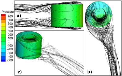
Fig. 7Flow patterns around bullet (α = 1)
3.2. The analysis of aerodynamic coefficient
According to published experiments and simulation results, the number has a direct impact on the structure of the flow field for cylinder. The relationship between drag coefficient and has important guiding significance for engineering application. At present, the relationship between the drag coefficient and Re for short cylinder ( < 1) with two free ends has not been proposed. For non-rotating short cylinders ( = 0.71) with two free ends, the relationship between and (as shown in Fig. 8) is obtained by changing the flow velocity . As can be seen from the figure, the average drag coefficient gradually decreases as increases. Because there is no boundary layer transition of the infinite cylinder and sphere, the average resistance coefficient of the short cylinder does not decrease rapidly in the critical region. In the non-critical region, the average drag coefficient of the short cylinder is between the infinite cylinder and the sphere. The Reynolds number has a greater influence on the average drag coefficient of the short cylinder than the long cylinder with two free ends.
Fig. 8The relation between short cylinder Cd and Re is compared to infinite cylinder, sphere [4] and long cylinder with two free end [12]
![The relation between short cylinder Cd and Re is compared to infinite cylinder, sphere [4] and long cylinder with two free end [12]](https://static-01.extrica.com/articles/19912/19912-img14.jpg)
Fig. 9Time histories of cd and cl of TSB (L/D = 0.7)
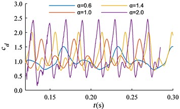
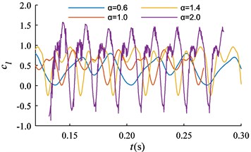
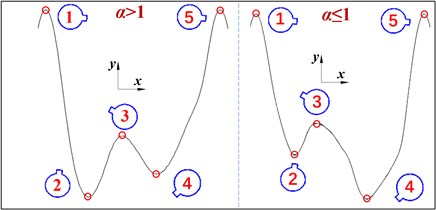
The time histories of and for the TSB are shown in Fig. 9 with different . Both and exhibit a single-periodic vibration with multiple extremes. The waveform of the can be summarized as the ‘W’ shape shown in Fig. 9 within a single cycle. That is, there are two local maximum points with same value, and two local minimum points with different values. In a single period, when > 1, the global minimum point of the cd is located at position 2 in Fig. 10(a); when ≤ 1, the minimum point of the is located at position 4 in Fig. 10(a). Similarly, in a single cycle, the waveform of can be summarized as the ‘M’ shape shown in Fig. 10(a). That is, there are two local minimum points with same value, and two local maximum points with different values.
Fig. 10The wave structure of the cd for TSB, and statistical results of aerodynamic coefficients
a)
b)
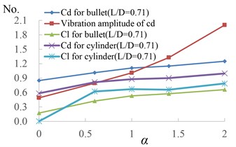
The statistical results of the average aerodynamic coefficients of rotating short cylinders and rotating TSB are shown in Fig. 10(b). Due to the presence of the detector, when = 0, the of the bullet is not zero, and its value is greater than the of the short cylinder. With the increase of , the aerodynamic coefficients of the bullets and short cylinders both increase, and the vibration amplitudes of and increase rapidly in the form of approximately quadratic functions. The curve of the bullet and short cylinder is approximately linear. From the time history curve of in Fig. 9, it can be seen that appears negative value with the increase of , that is, the direction of lift changes. Therefore, when ≥ 0.5, the average lift coefficient of the bullet is less than that of the short cylinder.
4. Conclusion
In this paper, the numerical simulation method is used to study the flow field characteristics of the short cylinder with double free ends, and the variation law of aerodynamic coefficients with different aspect ratios and Reynolds numbers is analyzed. On this basis, the flow field structure of rotating short cylinders and bullets is analyzed, and the influence of relative rotating speed on the aerodynamic coefficients of the short cylinder and the last sensitive bullet is compared and analyzed.
The main conclusions are as follows: (1) Unlike infinite cylinders and spheres, the of the short cylinder ( = 0.71) does not drop sharply in critical region. (2) Due to the periodic interference of the detector, the aerodynamic coefficient of the rotating TSB is periodically vibrated, and its vibration frequency is the same as the rotating speed of the TSB. The waveform of the is ‘W’ shape, and the waveform of the is ‘M’ in a single cycle. (3) With the increase of the , the vibration amplitude of the aerodynamic coefficient of the TSB rapidly increases in the form of a quadratic function, and and also increase.
References
-
Yang Yongliang, Guo Rui, Liu Rongzhong, et al. Study on the steady scanning motion of a smart submunition with rotary self-stabilization. Journal of Projectiles, Rockets, Missiles and Guidance, Vol. 2016, Issue 1, 2016, p. 49-52.
-
Yang Yongliang, Liu Rongzhong, Guo Rui, et al. Motion characteristic analysis of rotary self--stabilizing terminal sensitive submunition. Journal of National University of Defense Technology, Vol. 40, Issue 1, 2018, p. 145-150.
-
Chen Liang, Liu Rongzhong, Guo Rui, et al. Numerical simulation of forming process of multi-effect MEFP. Journal of Projectiles, Rockets, Missiles and Guidance, Vol. 2015, Issue 3, 2015, p. 55-57.
-
Schlichting H., Gersten K. Boundary-Layer Theory – 8th Revised and Enlarged Edition. Springer, 2000.
-
Zdravkovich M. M. Aerodynamics of bicycle wheel and frame. Journal of Wind Engineering and Industrial Aerodynamics, Vol. 40, Issue 1, 1992, p. 55-70.
-
Pattenden R. J., Bressloff N. W., Turnock S. R., et al. Unsteady simulations of the flow around a short surface-mounted cylinder. International Journal for Numerical Methods in Fluids, Vol. 53, Issue 6, 2007, p. 895-914.
-
Zdravkovich M. M., Brand V. P., Mathew G., et al. Flow past short circular cylinders with two free ends. Journal of Fluid Mechanics, Vol. 203, Issue 203, 1989, p. 557-575.
-
Zdravkovich M. M., Flaherty A. J., Pahle M. G., et al. Some aerodynamic aspects of coin-like cylinders. Journal of Fluid Mechanics, Vol. 360, Issue 360, 2000, p. 73-84.
-
Inoue O., Sakuragi A. Vortex shedding from a circular cylinder of finite length at low Reynolds numbers. Physics of Fluids, Vol. 20, Issue 3, 2008, p. 2742.
-
Prosser D. T., Smith M. J. Three-Dimensional Bluff Body Aerodynamics and Its Importance for Helicopter Sling Loads. 2014, http://hdl.handle.net/20.500.11881/3494.
-
Prosser D. T., Smith M. J. Numerical characterization of three-dimensional bluff body shear layer behavior. Journal of Fluid Mechanics, Vol. 799, 2016, p. 1-26.
-
Gao W., Nelias D., Liu Z., et al. Numerical investigation of flow around one finite circular cylinder with two free ends. Ocean Engineering, Vol. 156, 2018, p. 373-380.
About this article

The authors would like to acknowledge the financial supports from the National Natural Science Foundation of China (Grant No. 11372136), the Special fund for basic Scientific Research of Central University (Grant No. 30916011306) and the Postgraduate Research and Practice Innovation Program of Jiangsu Province (Grant No. KYCX17_0386).
