Abstract
This paper explores the transient mechanics mechanism of the projectile with double rotating bands engraving into the rifle and the propellant gas pressure distribution law during the rotating band engraving process. Previous studies usually ignored the coupling of projectile, artillery, and gunpowder parameters during the engraving process. To end this, taking a large-caliber artillery system as the research object, a projectile-barrel-charge coupled finite element model is established based on the two-phase flow interior ballistic theory and the finite element method, followed by numerical simulation. Through the comparison with experimental results, such a modeling method is proved to be effective.
Highlights
- The transient mechanics mechanism of the projectile with double rotating bands engraving into the rifle is explored.
- A projectile-barrel-charge coupled finite element model is established based on the two-phase flow interior ballistic theory.
- Such modeling method is proved to be effective through the comparison with experimental results.
1. Introduction
During the launching process of the artillery, the engraving process of the projectile rotating band is a highly nonlinear, transient dynamic process involving instantaneous impact, material failure and damage, and large geometric deformation, and has a great influence on many interior ballistic parameters, such as the gas pressure and initial velocity.
Due to the short time of the engraving process and the difficult experimental conditions, current researchers mostly use numerical simulations to study it. Sun et al. [1] used the measured pressure load as the load condition, and studied the dynamic engraving process of the rotating band through numerical simulation, thus the maximum resistance, engraving pressure, and projectile velocity at the corresponding time was obtained. Xu et al. [2] discussed the influence of band material and rifle on the engraving process through numerical simulation. However, in terms of load conditions, none of the above studies considered the change of interior ballistic performance caused by the engraving process. Jiyang and Qian [3] used the ABAQUS® subroutine development function to incorporate the classical interior ballistics model into the software, thus established a coupled interior ballistic-engraving finite element model. Based on this, Keinänen et al. [4] studied the influence of different rotating band structures on the stress and strain of the barrel. However, due to the simplification of classical interior ballistics in many aspects, the numerical results have certain deviations. Moreover, Li et al. [5] considered the interior ballistic equation of the engraving process and established a thermo-mechanical coupling dynamics model, through which the influences of the clearance between projectile and barrel, initial velocity, and initial projectile attitude on the resistance, projectile velocity, propellant gas pressure, and projectile attitude were analyzed. Ding and Zhang [6] conducted the numerical simulations on the engraving and subsequent interior ballistic processes, and concluded that the secondary work coefficient of classic interior ballistic was not constant and had extreme values. This further demonstrates the importance of using a more accurate numerical calculation model for interior ballistics. Sun et al. [7] studied the effects of different charge numbers on projectile motion, dynamic engraving force, and the engraving shape of the rotating band. The burning process of the propellant charge and the engraving process are inseparable, and it is impossible to expose the core of such a system problem in isolation.
The current researches mostly focus on the influence of the rotating band structure, and the barrel structure, however, the propellant charge parameters are rarely studied. It is necessary and important to study the influence of the propellant charge parameters on the engraving process. The premise is that an accurate coupling model of the interior ballistics and the engraving process must be established.
In this paper, the more accurate two-phase flow interior ballistic theory is used to describe the interior ballistic characteristics, and a dynamic, coupling finite element model of the engraving-interior ballistic is established using the ABAQUS® subroutine development function and FORTRAN®. Through the comparison with experimental results in Ref. [8], such a modeling method is proved to be effective.
2. Quasi-one-dimensional two-phase flow internal ballistics model
To better simulate the burning law of gunpowder in the chamber during the engraving process of the projectile rotating band, the quasi-one-dimensional two-phase flow internal ballistic theory is adopted to establish the calculation model of gas pressure. The conservative form of the basic equation of quasi-one-dimensional two-phase flow interior ballistic can be written as follows:
where is the conservation vector variable at time , is the flux vector on the -axis of projectile motion, is the source term. They can be further written as follows:
To close the basic equations of the two-phase flow interior ballistic, the following necessary auxiliary equations are constructed according to the physical and chemical properties of the two-phase material:
where is gun barrel cross-sectional area, is the density of the medium, is the gas velocity, is the gas pressure, is the gas specific interior energy, is the gunpowder burning heat, is the percentage of gunpowder burned, is the specific heat ratio, is the gunpowder gas residual capacity, is the gunpowder density, is the relative burned thickness, is the burning rate, is the thickness of gunpowder, , , and are the shape parameters of gunpowder, is the burning temperature of gunpowder gas, is the gunpowder gas constant. Eqs. (3-6) are, respectively, the state equation, the burning rate equation, the gunpowder combustion shape function, and the surface temperature equation.
Convert Eqs. (1)-(6) into Lagrange coordinates, and then use the classic Von Neumann Richtmyer difference format for discretization. This numerical calculation method is a conditionally stable algorithm, and its step length needs to satisfy the following conditions:
where , , is the speed difference between two adjacent gunpowder gas grids.
The numerical calculation grid adopts real-time grid update technology. To avoid the numerical oscillation problem that may occur in the computational process, the artificial viscosity term q is added to improve the stability of the numerical method.
Assuming that the impact of the recoil of the artillery is not considered, the bottom of the chamber is regarded as a static wall, i.e.:
The movement boundary at the bottom of the projectile can be written as:
where , is the mass of gunpowder, is the virtual coefficient, is the mass of the projectile.
3. Coupled interior ballistic-engraving finite element model
3.1. Finite element modeling of engraving
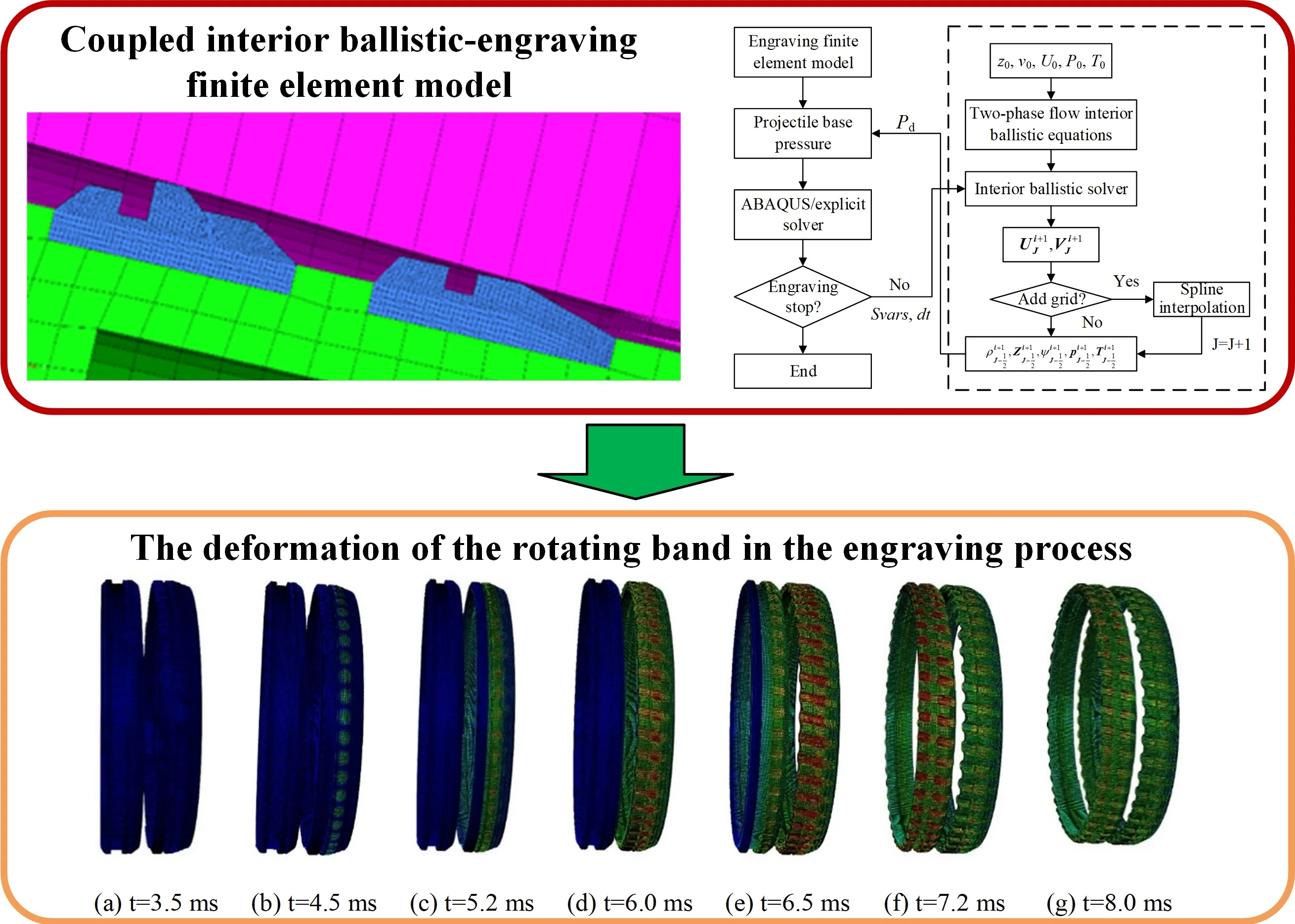
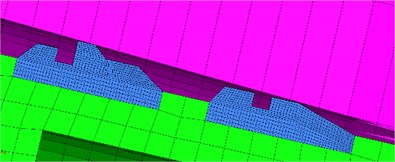
Taking a large-caliber artillery system as the research object, the finite element pre-processing software is used to discretize the barrel, projectile, and rotating band, in which the rotating band is modeled using the eight-node hexahedral reduced integral unit (C3D8R). Considering that the deformation of the projectile is small during the engraving process, to improve the computational efficiency, the projectile is rigidized. The established finite element model of the engraving process is shown in Fig. 1.
Fig. 1Finite element model of the engraving process
The material of the barrel is PCrNi3MoVA, and the material of the rotating band is copper. Considering that the rotating band will undergo large elastoplastic deformation and damage during the engraving process, the classical Johnson-Cook plastic failure criterion is used to describe the material behavior in the engraving process. The detailed Johnson-Cook constitutive parameters of copper material are given in Table 1.
The point-surface contact algorithm using the penalty function is used to simulate the contact relationship between the exterior surface of the rotating band and the interior wall of the barrel. Moreover, the surface-surface contact algorithm is used to simulate the contact relationship between the bourrelet of the projectile and the interior wall of the barrel. The Coulomb friction coefficient is 0.1. As that there is no relative movement between the interior surface of the rotating band and the projectile, a fixed constraint is adopted, and the bottom of the barrel is fully constrained.
Table 1Johnson-Cook constitutive parameters of copper material
Item | / MPa | / MPa | / K | / K | |||||||
Value | 90 | 292 | 0.31 | 1.09 | 1356 | 293 | 0.54 | 4.89 | 3.03 | 0.014 | 1.12 |
3.2. Coupling computation of the engraving process and interior ballistic
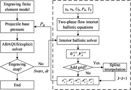
In this paper, the ABAQUS® subprogram interface VUAMP is used to realize the coupling of the two-phase flow interior ballistic and engraving dynamics model. The velocity, displacement, and pressure of the projectile are approximated by those of the fluid grid after the projectile, and the real-time data is stored in the state variable storage of ABAQUS® software. When 0, the projectile base pressure is taken as the initial force condition of the engraving finite element model. When adding an analysis step , the velocity and displacement obtained by the engraving finite element model are transferred to the two-phase flow interior ballistic program as the boundary conditions, thus the projectile base pressure in the next step is calculated. The detailed solving process is shown in Fig. 2.
Fig. 2Solving process of the coupled interior ballistic-engraving finite element model
4. Simulation experiment and discussion
The numerical simulation of the projectile engraving process is carried out, and Fig. 3 shows the displacement and velocity of the projectile with time. Moreover, Fig. 4 gives the base pressure and breech pressure curves. When the engraving process is completed, the displacement of the projectile is 101.2 mm. Fig. 3 and 4 show that the end time of the engraving process is 3.675 ms, the projectile velocity at this time is 86.78 m/s, and the corresponding base pressure and the breech pressure are 215.02 MPa and 234.3 MPa, respectively.
Fig. 5 shows the dynamic engraving force with respect to the projectile displacement. It can be seen that point r1 appears when the displacement is 54.7 mm, i.e. the front rotating band begins to engrave into the rifle. The growth rate of the deformation of the front rotating band decreases as the displacement increases during this process. Point r2 appears at the displacement of 70.2 mm, when the front rotating band has fully engraved into the rifle. Since then, the engraving resistance force mainly comes from the friction between the rear rotating band and the rifle. The displacement at point r3 is 78.0 mm. At this time, the rear rotating band begins to engrave into the rifle. After that, the contact area between the rotating band and the rifle decreases gradually, and the engraving force shows a rapid decline.
Fig. 3Displacement and velocity of the projectile
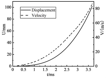
Fig. 4Base pressure and breech pressure
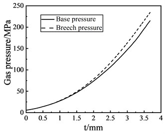
Fig. 5The dynamic engraving force with respect to the projectile displacement
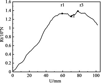
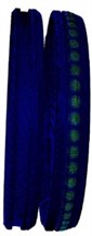
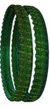
Fig. 6The deformation of the rotating band in the engraving process

a)3.5 ms
b)4.5 ms

c)5.2 ms

d)6.0 ms

e)6.5 ms

f)7.2 ms
g)8.0 ms
Fig. 6 shows the deformation of the rotating band in the engraving process. Fig. 6(a) is the condition before time is 3.5 ms, the deformation of rotating band is at a relatively low level. The rotating band only occurred elastic deformation, but no material fracture. Fig. 6(b) shows that when time is 4.5 ms, material failure and fracture occurred in some areas of the rotating grid, and the rotating band has shown deformation and grooves. Fig. 6(c) shows that at 5.2 ms, the first rotating band has broken, and Fig. 6(d) shows that the engraving process of the first rotating band has finished. Fig. 6(e) shows that the front part of the second rotating band is squeezed and deformed when time is 6.5 ms. Fig. 6(g) shows the rotating band after engraving process when time is 8.0 ms.
Table 2 shows the comparison between the numerical simulation results of the coupled engraving model established in this paper and the experiment data given in Ref. [8]. It can be seen that the accuracy of such modeling is verified.
Table 2The comparison with the experiment data
Item | Simulation results | Experiment date |
Groove depth (mm) | 2.28 | 2.25-2.38 |
Groove width (mm) | 3.83 | 3.81-3.92 |
Base pressure after the engraving process (MPa) | 215.02 | 221.51 |
Base pressure at the maximum engraving force (MPa) | 182.30 | 196.27 |
Projectile velocity at the maximum engraving force (m.s-1) | 70.32 | 73.32 |
5. Conclusions
Previous studies usually ignored the coupling of projectile, artillery, and gunpowder parameters during the engraving process. To end this, this paper simulates the engraving process of a large-caliber artillery system by establishing the coupling calculation model of the two-phase flow interior ballistic and the finite element model. Through the comparison with experimental results, such a modeling method is proved to be effective. The numerical results show that the engraving force increases continuously in the engraving process. However, the maximum value of engraving resistance does not appear at the end of the engraving process, but appears at the inflection point where the contact area between the rotating band and the barrel becomes smaller.
References
-
Sun Q., Yang G., Wang P., et al. Numerical research on rotating band engraving process of a large-caliber howitzer. Acta Armamentarh, Vol. 36, Issue 2, 2015, p. 206-213.
-
Xu Y., Ding H., Xu J., et al. Numerical analysis of influence of rifling structure of large caliber gun on moving of projectile with sliding driving band in bore. Acta Armamentarh, Vol. 37, Issue 11, 2016, p. 2148-2156.
-
Jiyang Z., Qian J. Dynamic response of fixed cartridge case during engraving process under different in-bore free path. Journal of Ballistics, Vol. 30, Issue 1, 2018, p. 55-60.
-
Keinänen H., Moilanen S., Tervokoski J., et al. Influence of rotating band construction on gun tube loading – part I: numerical approach. Journal of Pressure Vessel Technology, Vol. 134, Issue 4, 2012, p. 041007.
-
Li M., Qian L., Sun H. Research on coupled thermo-mechanical model during rotating band engraving process. Acta Armamentarh, Vol. 37, Issue 10, 2016, p. 1803-1811.
-
Ding C., Zhang X. Simulation study of bearing band engraving process and interior ballistic process based on thermo-mechanical coupling FEA model. Acta Armamentarh, Vol. 36, Issue 12, 2015, p. 2254-2261.
-
Sun Q., Yang G., Ge J. Modeling and simulation on engraving process of projectile rotating band under different charge cases. Journal of Vibration and Control, Vol. 23, Issue 6, 2017, p. 1044-1054.
-
Sun Q. Study on Dynamics of Rotating Band Engraving for Large Caliber Howitzers. Ph.D. Dissertation, Nanjing University of Science and Technology, 2015.
Cited by
About this article

