Abstract
The change of ambient temperature will cause the change of gunpowder burning rate, which will directly affect the ballistic performance of the projectile and cause the change of the overload of the projectile fuze system. In this study, the numerical simulation program of the interior trajectory of a large-caliber gun was established by MATLAB, and the variation rules of the corresponding trajectory parameters at different temperatures were obtained. ANSYS finite element software is used to analyze the force of the projectile fuze system under different ambient temperatures. The results show that under the same loading conditions, with the increase of ambient temperature, the maximum pressure in the gun bore and the muzzle velocity of the projectile increase significantly, and the stress and strain of the projectile fuze system in the bore increase gradually. The numerical simulation results are in good agreement with the theory, which reveals the influence of ambient temperature on the overload in the bore of the projectile fuze system to a certain extent, and provides theoretical support for the study of internal ballistics, charge design and gun use.

1. Introduction
The ballistic performance of a projectile is greatly influenced by the environment. Even with the same loading conditions, the ballistic performance of artillery varies significantly at different ambient temperatures. In some cases, the difference in muzzle velocity between high and low temperatures can be as large as 100 m/s, and the variation in maximum chamber pressure can range from 40 MPa to 80 MPa [1]. The overload of the projectile serves as the power source for certain mechanisms within the mechanical fuze system, and the differences in ballistic performance caused by temperature variations have a significant impact on the movement of fuze components [2].
Currently, numerous domestic and international scholars have conducted extensive research on the influence of ambient temperature on the firing conditions of projectiles. Luo Yunjun et al. believe that, given the determined structure of the artillery and type of propellant, temperature affects the burning rate of propellant, subsequently influencing chamber pressure and muzzle velocity. They provide several methods for reducing the temperature coefficient of the propellant charge [3]. A. I. Atwood, T. L. Boggs, and others present combustion rate data for three compounds used in propellants and explosives, considering different initial temperatures and pressures. They study the dependence of the burning rate of ammonium perchlorate (AP), HMX, and RDX on initial temperature and pressure [4].
In this paper, based on existing relevant literature and utilizing finite element numerical simulation software, we construct a numerical simulation model of the interior ballistics of the projectile fuze system at different ambient temperatures. This model reveals the influence of ambient temperature on the overload of the projectile fuze system, providing strong support for related ballistic experiments.
2. Interior trajectory calculation
The impact of ambient temperature on the interior ballistic performance is mainly reflected in the changes in the burning rate of the propellant.
According to the Arrhenius law, it is known that as the initial temperature increases, the burning rate of propellant increases exponentially [5]. The formula for burning rate of the propellant can be expressed as:
the rate of gas generation in propellant can be expressed as:
Among them, represents the burning rate temperature coefficient, which is related to the initial temperature and composition of the propellant. represents a characteristic parameter of the propellant shape. represents the relative surface area (the ratio of the burning surface area to the initial burning surface area). is half of the initial arc thickness of the propellant.
From Eq. (1) and Eq. (2), it can be seen that the initial temperature of the propellant changes the burning rate, thereby affecting the gas generation rate of the propellant. When other conditions influencing the burning rate of the propellant are constant, the burning rate temperature coefficient can be obtained through closed bomb tests. According to literature [6], the burning rate temperature coefficient of a certain large-caliber projectile propellant is shown in Table 1 [6].
It can be seen from Table 1 that with the increase of ambient temperature, the burning rate temperature coefficient of the propellant increases significantly.
Table 1Influence of ambient temperature on burning rate coefficient
/ °C | / ×106 dm⋅s-1⋅MPa-1 |
+50 | 8.50 |
15 | 7.95 |
–40 | 7.34 |
3. Interior trajectory calculation
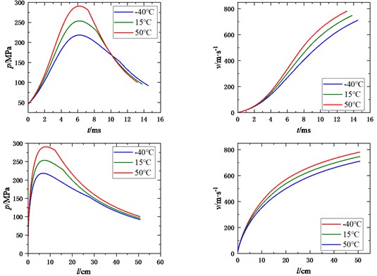
According to the classical interior trajectory equation, the interior trajectory program is written by MATLAB software and solved by the fourth-order Runge Kutta method. Its advantage is that the step size can be changed arbitrarily in the calculation, and there is no problem of starting the calculation, which is suitable for the calculation of the internal trajectory cycle. The obtained correlation curves of chamber pressure and velocity with time and migration at different ambient temperatures, as well as the relevant internal ballistic parameters of special points are shown in Fig. 1 and Table 2.
4. Simulation design
4.1. Simulation model
The large-caliber projectile consists of four parts: the projectile body, the warhead fuse, the explosive and the projectile belt. The model is a spiral body with simple geometric structure. Based on the main dimension parameters, the three-dimensional model of the projectile and barrel is drawn with SolidWorks software. The three-dimensional model is imported into HyperMesh software for mesh division, and finally the finite element software is used for analysis and solution.
Table 2Values of special points of different ambient temperatures
Temperature / ℃ | Special point | / ms | / cm | / (m·s-1) | / MPa |
–40 | Maximum pressure point | 6.2031 | 6.76 | 283.6 | 214.13 |
Muzzle point | 15.61 | 59 | 743.78 | 74.72 | |
15 | Maximum pressure point | 6.1947 | 7.38 | 318.62 | 260.01 |
Muzzle point | 15.1501 | 59 | 786.44 | 78.08 | |
50 | Maximum pressure point | 6.1779 | 7.977 | 352.657 | 285.2 |
Muzzle point | 14.3084 | 59 | 815 | 82.07 |
Fig. 1Influence of initial temperature on ballistic performance

On the basis of the conventional finite element analysis method, FEM coupling SPH method is used for the part of the elastic belt with large deformation during the extrusion process of the projectile. The Lagrange finite element method is used for the regions with small deformation such as the barrel and the projectile body. This not only makes full use of the ability of SPH method to simulate large deformation, but also avoids the calculation difficulties caused by mesh distortion in finite element method, and improves the calculation efficiency and accuracy. ANSYS/LS-DYNA explicit dynamics were used for analysis, and solid64 six-integrated Lagrange elements were used to mesh the barrel and the projectile. The grid division of each component and the local model of projectile and gun coupling are shown in Fig. 2.
4.2. Material model
The tube material is 35CrMnSiA, the elastic band is copper, and the Johnson-Cook constitutive relation model is adopted in its plastic stage. The J-C model is an empirical viscoplastic model, which has been widely used in the research field of high load and high speed impact. It was proposed in 1983 to describe the constitutive relation model of material damage under high strain rate. The empirical formula is as follows [7]:
where: is mises yield stress; is the yield strength under quasi-static test; , are strain strengthening parameters; is the empirical strain rate sensitivity coefficient; is the temperature softening index; is the equivalent plastic strain; is dimensionless equivalent plastic strain rate, and is the relative temperature:
where: is the reference temperature (one is room temperature); is the melting temperature of the material under normal conditions. The material parameters are shown in Table 3, the constitutive relation parameters of elastic belt materials are shown in Table 4.
Fig. 2Grid division of each component


Table 3Types and properties of materials
Materials | Missile body 35CrMnSiA | Fuze body 7A04-T6 | Explosive Composition B | Percussion cap |
Density | 7.76 | 2.85 | 1.68 | 8.5 |
Modulus of elasticity | 203 | 69 | 15 | 103 |
Modulus of elasticity | 85 | 26 | 1.7 | 26 |
Yield limit/MPa | 1320 | 430 | 100 | 135 |
Strength limit/MPa | 1620 | 600 | 390 | |
Poisson's ratio | 0.3 | 0.31 | 0.4 | 0.31 |
Table 4Plastic J-C constitutive parameters of elastic band materials
Materials | / MPa | / MPa | |||
Copper | 90 | 292 | 0.31 | 0.025 | 1.09 |
4.3. Calculation results and analysis
4.3.1. Calculation results of the extrusion process
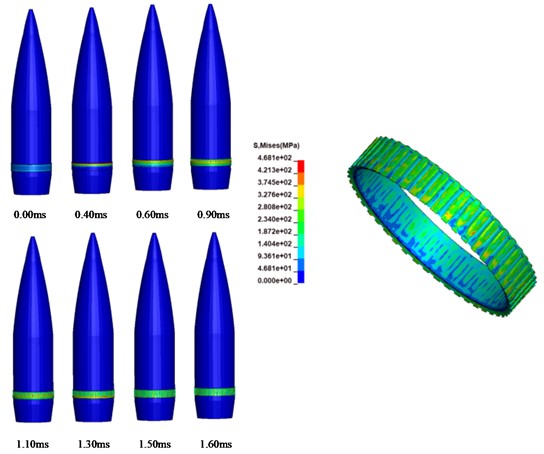
Because the extrusion time is relatively short, and at the beginning stage, the pressure in the chamber is not large, and the force of the projectile fuze system is small, the projectile fuze system is treated as a rigid body in the extrusion stage, and the force of the projectile fuze system is not considered. Fig. 3 shows the equivalent stress and deformation distribution of the elastic belt extrusion process calculated by the FEM-SPH method. It can be seen from Fig. 3 that at 0.60 ms, a large number of SPH particles appear in the contact area between the projectile belt and the body tube, and these particles can continue to act as the medium of the projectile and the body tube to achieve the transfer of force between the projectile and the body tube. If solved by FEM, the deformation of these elements is more serious, resulting in a decrease in calculation accuracy, and the stable calculation time and step size will be greatly reduced. The method of converting severely deformed cell mesh into SPH particles can improve the accuracy and reliability of simulation results to a certain extent. As the projectile moves forward, more and more SPH particles appear in the projectile belt, and these particles are mainly distributed in the area where the projectile belt touches the positive line. At about 1.30 ms, the trailing edge of the band moves to the beginning of the rifling. Finally, the cartridge band was completely squeezed into the body tube near 1.50 ms. In the initial stage of extrusion, the deformation of the elastic band is small, and the corresponding stress is also small. As can be seen from the figure, when the projectile is completely squeezed into the rifling, the pressure on the projectile belt is about 468 MPa, and then tends to stabilize.
Fig. 3The process and result of elastic band extrusion calculated by SPH-FEM

4.3.2. Calculation result after extrusion
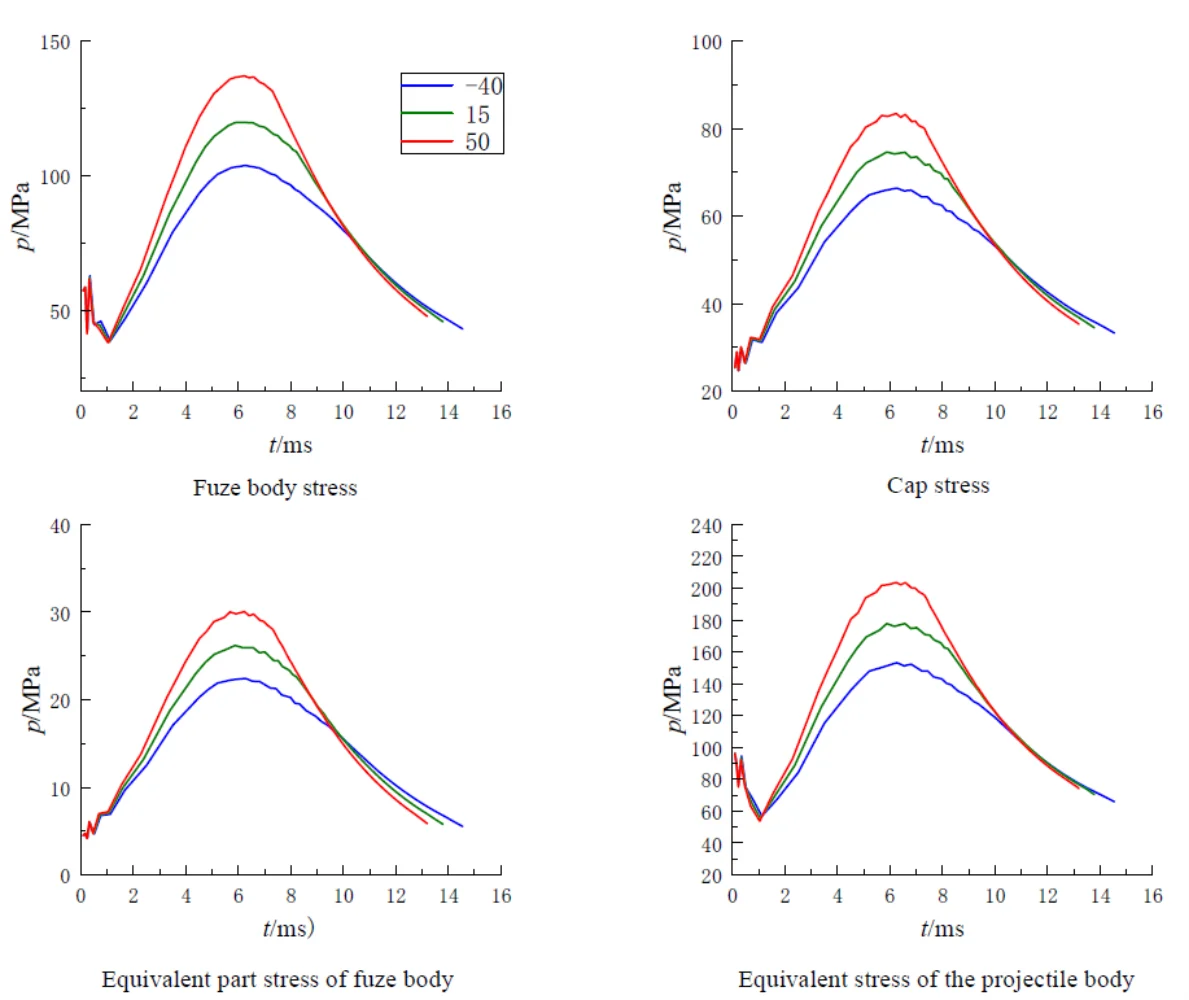
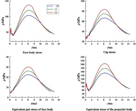
In order to facilitate the analysis of the results after extrusion, the force of rifling on the elastic belt was regarded as a fixed 463 MPa after extrusion, and the model was simplified into a two-dimensional axis symmetric form, which reduced the complexity of modeling and meshing, improved the computational efficiency of the model, facilitated post-processing, and grid encryption was carried out for some possible dangerous products. Compared with the warhead fuze, the bomb base fuze has to bear the pressure of gunpowder gas directly, so the load in the chamber is greater, so this paper focuses on the analysis of the stress and strain of the bomb system when the fuze is placed on the bomb base. Some parts inside the fuze can withstand relatively small forces, this part is regarded as a whole, and its equivalent density is determined, and its mechanical properties are assumed to be equivalent to explosive charge. The other part (inside the bottom percussion cap) cannot be stressed, this part is defined as a cavity, and its mass is transferred to the equivalent part inside the fuze. Fig. 4 is a two-dimensional schematic diagram of the fuze placed on the bottom of the bomb, and the force between the bomb body and the fuze parts is shown in Fig. 5. As can be seen from the figure, with the increase of ambient temperature, both the bomb body and the fuze body are subjected to increased stress and strain, and the maximum stress and strain point appear near the maximum pressure point of the chamber. When the temperature is 50 ℃, the projectile is subjected to the greatest stress, and the maximum stress point is 816 MPa on the projectile body, which is far less than the yield limit of the projectile body material 1320 MPa. The maximum strain of the projectile body is 0.034 mm, and the shape variable meets the strength requirements. At high temperature of 50 ℃, the maximum stress of the fuze body is 548 MPa, which is close to the strength limit of the fuze body.
Fig. 4Schematic diagram of the projectile with the base fuse

Fig. 5Stress-strain diagram of fuze body and bomb body

5. Conclusions
In this paper, the finite element numerical simulation method is used to build the internal ballistic model of the projectile fuze system. According to different ambient temperatures, the internal ballistic overload of the projectile fuze system is studied, and the following conclusions are drawn:
1) Under the condition that other loading conditions remain unchanged, with the increase of ambient temperature, the maximum chamber pressure of the gun, the muzzle velocity of the projectile, the muzzle speed and the maximum recoil overload coefficient are significantly increased. The muzzle velocity at high temperature 50 ℃ is 3.68 % higher than that at normal temperature 15 ℃, and 9.69 % higher than that at low temperature –40 ℃. The maximum chamber pressure at high temperature 50 ℃ is 14.23 % higher than that at normal temperature 15 ℃, and 33.18 % higher than that at low temperature –40 ℃. With the increase of ambient temperature, the charging energy is more fully utilized.
2) With the increase of ambient temperature, the stress and strain of the projectile fuze system in the chamber increase significantly, and the maximum stress-strain point appears near the maximum pressure point of the chamber. When the temperature is 50 ℃, the projectile is subjected to the greatest stress, and the maximum stress point is 816 MPa on the projectile body, which is far less than the yield limit of the projectile body material 1320 MPa. The maximum strain of the projectile body is 0.034 mm, and the shape variable meets the strength requirements. When the high temperature is 50 ℃, the maximum stress of the fuze body is 548 MPa, which is close to the strength limit of the fuze body, so the high ambient temperature will lead to the safety factor is too small.
References
-
Z. S. Wang, W. D. He, and F. M. Xu, “Design principle and technology of artillery firing charge,” Beijing Institute of Technology Press, Beijing, 2014.
-
J. H. Yu, “Design and simulation of firing environment simulation test system for large caliber projectile fuze,” Nanjing University of Science and Technology, Jiangsu, 2017.
-
Y. J. Luo et al., “Method of reducing temperature coefficient of propellant charge,” Journal of Taiyuan Institute of Machinery, Vol. 15, pp. 4–6, 1994.
-
J. R. Osborn, J. P. Renie, and J. M. Murphy, “Effect of erosive burning on pressure and temperature sensitivity,” Acta Astronautica, Vol. 11, No. 7-8, pp. 459–467, Jul. 1984, https://doi.org/10.1016/0094-5765(84)90086-9
-
X. B. Zhang, “Ballistics in guns,” Beijing Institute of Technology, Beijing, 2014.
-
Z. S. Wang, “Principle of gunpowder charge design,” Weapons Industry Press, Beijing, 1995.
-
P. Wang, G. L. Yang, and J. J. Ge, “Numerical simulation of elastic belt extrusion process based on Johnson-Cook constitutive model,” Journal of Ballistic Science, Vol. 27, No. 2, pp. 55–61, 2015.
About this article
The authors have not disclosed any funding.
The datasets generated during and/or analyzed during the current study are available from the corresponding author on reasonable request.
The authors declare that they have no conflict of interest.
