Abstract
In modern war, the special ammunition launched by mortars contains photoelectric components, which can’t bear high overload, so low overload launching is required. This paper creatively conceives the integrated structure of projectile and inverted high-pressure chamber without changing the mortar tube’s original structure design. The flow field in the bore is modeled and simulated by using classical interior ballistics and FLUENT, and the difference between the chamber pressure of the inverted high-pressure chamber structure and the traditional structure are analyzed. The simulation results show that the initial motion law of the projectile launched by the inverted high-pressure chamber structure is different from that launched by the original structure. Chamber pressure has two peaks, the peak value decreases by 25 %, the velocity increases by 5 %, and the displacement increases by 60 %.
1. Introduction
Because the trajectory of the mortar is very curved, there is no dead boundary for shooting, and it can attack hidden targets that cannons and howitzers cannot shoot [1]. Mortars have unique advantages on the battlefield. In modern war, the launch of Modern Special Ammunition also puts forward requirements for the internal ballistic performance of mortars. The overload of traditional mortars at full load greatly exceeds the bearing limit of new ammunition.
Luo Zongyi, Zhang Jiuyun and Zhang Shilin [2] aimed at the structural characteristics of the small-caliber low-overload launch system, by installing a pressure sensor at the bottom of the gun bore to measure the pressure in the low-pressure bore, and experimentally studied the chamber pressure variation law of the low-overload launch system. Hao Xin, Wang Jianzhong, Shi Jiadong, et al. [3] took the piston-type high and low pressure launch experimental device of the throwing robot as the object, and collected the overload information of the throwing robot by setting the impact acceleration sensor inside the throwing robot.
In addition to experimental methods, there are also numerical simulations to study the low-overload launch process. Li Enyi et al. [4] used the renormalization group - turbulence model to simulate the flow field flow, and studied the influencing factors of the internal trajectory of the low-overload launch. Hu Xiaolei et al. [5] used the finite rate/vortex dissipation model to simulate the secondary combustion process of gas jet and air in the primary combustion chamber, and used the domain dynamic layered mesh update method to study the effect of secondary combustion on low-overload launch.
Due to the transient high temperature and transient high pressure characteristics of the physical field in the gun bore, the information collected by the experimental method cannot fully reflect the movement law of the projectile during the launch phase. However, classical internal ballistics cannot perfectly solve the problem of fluid flow, and computational fluid dynamics cannot solve the problem of chamber pressure change caused by gunpowder combustion in a short time. Therefore, on the premise of proposing a low-overload launch model based on projectiles, this paper solves the high-pressure chamber pressure time-varying curve generated by the combustion of gunpowder through classical internal ballistics, and then loads the high-pressure chamber pressure time-varying curve as a boundary condition into FLUENT for Numerical Simulation. Then, the difference between the projectile motion law launched by the inverted high-pressure chamber structure and the projectile motion law launched by the traditional structure is analyzed.
The remainder of this paper is organized as follows. Section 2 mainly explains the mechanism of the integrated high-pressure chamber. Section 3 introduces the FLUENT simulation model and boundary condition settings, as well as the subsequent analysis of the simulation results. Finally, the conclusions are drawn in Section 4.
2. Low-overload launch model derivation
For combining the low-overload launch system with the existing mortar to realize low overload launch, it is envisaged to combine the high-pressure chamber with the projectile, place the propellant in the center of the high-pressure chamber, and drill several holes at the bottom surface of the high-pressure chamber. The mortar barrel and the bottom surface of the high-pressure chamber form a low-pressure chamber together.
Fig. 1Schematic diagram of inverted high-pressure chamber
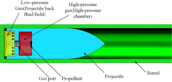
The launch principle of the low-overload launch system of the inverted high-pressure chamber is shown in Fig. 1. The propellant at the high-pressure chamber is ignited to produce high-pressure gas, which rapidly increases the gas pressure in the high-pressure chamber. The high-pressure gas enters the space between the bottom of the high-pressure chamber and the bottom of the gun barrel through the hole in the bottom of the high-pressure chamber. The gas pressure in the space between the bottom of the high-pressure chamber and the bottom of the barrel increases, pushing the projectile forward. Based on the classical interior ballistics theory, the burning rate and high-pressure chamber pressure of the propellant after ignition are calculated. As shown in Eq. (1):
where, is the relative burning thickness of powder particles; is the time; is the burning rate constant; is the initial thickness of 1/2 powder particles; is the pressure of high pressure chamber.
High pressure chamber pressure can be calculated as shown in Eq (2):
where, is the power of fire; is the charge quantity; is the percentage of gunpowder burned; is the powder density; is the residual volume of gunpowder gas; is the volume of high-pressure chamber.
directly determined by , as shown in Eq. (3):
where the selection of , , is related to the shape of gunpowder. In the experimental stage here, we selected square gunpowder, , , all are 1.
In the experimental scheme, we choose the emission mode of no perforated cladding. After the pressure change in the high-pressure chamber, the projectile back fluid field is directly affected by gas flow, in which the gas mass flow can be calculated as shown in Eq. (4):
where is the nozzle flow coefficient; is the flow area of gas pipe; and is the gas density and gas flow rate of the nozzle flow part, where and can be calculated as shown in Eqs. (5) and (6):
where is the air gas constant; is the gas pressure in projectile back fluid field; and are respectively the air pressure and temperature of the flow part of the nozzle; is the high pressure chamber gas temperature; is the adiabatic coefficient.
It can be seen from the previous formula that when propellant starts to burn, the pressure difference between high pressure chamber and projectile back fluid field will be changed, resulting in relative flow rate changing the projectile back fluid field pressure drives the movement of the system. The relative flow can be calculated as shown in Eq. (7):
After the flow is generated in the projectile back fluid field, the pressures in the high pressure chamber and projectile back fluid field can be calculated as shown in Eqs. (8) and (9):
where, is the cross-sectional area of the launch tube, is the displacement of the projectile, is the velocity of the projectile, is the mass of the projectile, is the secondary work calculation coefficient, is the length of the neck of the medicine chamber, which is the quotient of the initial volume of the projectile back fluid field and the cross-sectional area of the launch tube.
After knowing the pressure of the high-pressure chamber and projectile back fluid field at a certain moment and the force area at the bottom of the projectile, the force, overload, velocity and displacement of the projectile at a certain moment can be calculated by combining the kinematic equations. Through the iterative operation of the above formula by the Runge-Kutta method, the high-pressure chamber pressure time-varying curve can be solved as the boundary condition of the subsequent FLUENT numerical simulation.
3. Numerical simulation
3.1. Model and boundary settings
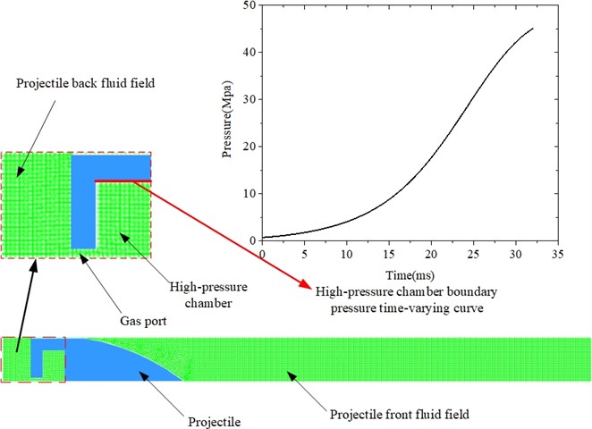
In order to improve the computational efficiency, a two-dimensional axisymmetric simulation model is established in this paper; the density-based implicit solver in FLUENT is selected because it can solve the compressible supersonic fluid problem well, and the transient solution method is selected; Use the ideal air model that comes with FLUENT instead of gunpowder gas. Before the calculation, it is necessary to control the control parameters, mainly the Courant number [6], in which the Courant number is selected as 1. The FLUENT simulation model and the dynamic pressure boundary applied to the pressure inlet in the simulation are shown in Fig. 2.
Fig. 2FLUENT simulation model
3.2. Simulation results and analysis
The comparison of the pressure time-varying curve of the projectile back fluid field with the inverted high pressure chamber structure in the early stage of launch and the traditional structure is shown in Fig. 3.
It can be seen from Fig. 3 that the pressure curve has obvious double peaks. The first peak occurred in 5 ms, with a size of 0.46 MPa, and the second peak occurred in 32 ms, with a size of 0.86 MPa. Compared with the peak of traditional structure launch, which occurred in 27 ms, with a size of 1.1 MPa, the maximum peak value of the inverted high-pressure chamber was delayed by 5 ms, down 15 %. As the chamber pressure has the first peak, the subsequent chamber pressure curve rises slowly, and the second peak becomes lower.
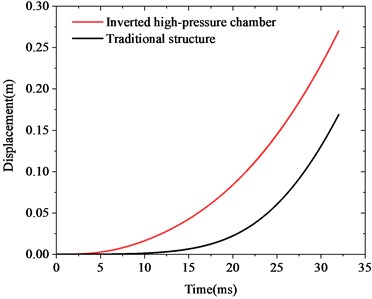
The comparison between the displacement time-varying curve and the velocity time-varying curve of the projectile under the inverted high pressure chamber structure and the traditional structure is shown in Fig. 4.
Fig. 3Pressure time-varying curve
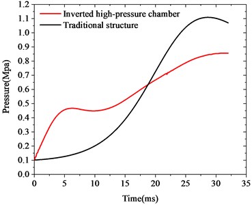
Fig. 4Displacement and velocity time-varying curve
a) Displacement
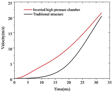
b) Velocity
Compared with the traditional structure, the displacement of the projectile of the inverted high-pressure chamber structure rises faster in the initial stage, and can make a faster response to the change of pressure. The displacement at the initial stage of launch is larger, rising from 0.17 m to 0.27 m, an increase of 60 %. Besides, the appearance of double peaks in the low-pressure chamber leads to the velocity curve of the projectile tending to be flatter than the traditional structure. At the same time, the saturated low-pressure chamber curve increases the initial launch velocity by 5 % from 20 m/s to 22 m/s.
4. Conclusions
Considering that modern special ammunition contains photoelectric elements with low overload resistance, this paper proposes a low overload launch model of inverted high-pressure chamber based on projectile. Based on the classical interior ballistic equation and FLUENT fluid simulation, The projectile motion law and the variation law of the chamber pressure in the projectile back fluid field in the early stage of the launch of the inverted high-pressure chamber structure were studied. The conclusions are as follows:
1) The inverted high-pressure chamber structure is prone to double-peak phenomenon of projectile back fluid field pressure at the initial stage of launch. The first peak appears at 5 ms with a size of 0.46 MPa, and the second peak appears at 32 ms with a size of 0.86 MPa. The double-peak pressure can reduce the peak pressure of the chamber pressure, and the increase of the chamber pressure curve can be slowed down.
2) The inverted high-pressure chamber structure can effectively reduce the overload by 25 % under the peak value of the high-pressure chamber of 47 MPa. This feature is suitable for launching modern special ammunition that has requirements for launching overload. The saturation of the curve has also increased, which is manifested as a 5 % increase in the initial ballistic velocity and a 60 % increase in displacement.
References
-
Shu Xiantong, Mortar Design Manual. (in Chinese), Beijing: National Defense Industry Press, 1984.
-
Luo Zongyi, Zhang Jiuyun, and Zhang Shilin, “Numerical simulation and test for interior ballistic trajectories of small caliber high-low pressure launching system,” (in Chinese), Mine Warfare and Ship Self-Defence, Vol. 25, No. 3, pp. 48–51, 2017.
-
Hao Xin et al., “Experimental study on launch overload of high-low pressure launcher for launchable robot,” (in Chinese), Journal of Taiyuan University of Technology, Vol. 44, No. 3, pp. 393–396, 2013.
-
Li Enyi et al., “Numerical study on factors of interior ballistic for low-temperature gas-ejection,” (in Chinese), Journal of Aerospace Power, Vol. 32, No. 6, pp. 1296–1306, 2017.
-
Hu Xiaolei et al., “Influence of secondary combustion on the load and internal trajectory of gas-ejection launcher,” (in Chinese), Journal of Solid Rocket Technology, Vol. 38, No. 6, pp. 776–781, 2015.
-
Wang Zongqian, “Fatigue analysis and optimization of vehicle cab under the action of a certain type of vehicle gun muzzle shock wave,” (in Chinese), Nanjing University of Science and Technology, 2016.
About this article

