Abstract
With the development of eddy current brake (ECB), they are widely used in life and military. Through the ECB, the resistance is converted into thermal energy and dissipated in the air. Thermal energy will make the temperature rise and the heat cannot be dissipated quickly. The electromagnetic characteristics of many parts in the ECB are very sensitive to temperature. Therefore, the study of temperature field is very important for it. This paper takes the linear cylindrical ECB as an example to study the heat generated under the intense impact and high speed condition. The temperature field is calculated through finite element method (FEM) ways. According to the temperature distribution characteristics, the cooling measures of permanent magnet brake are studied to effectively reduce the temperature rise of the brake, ensuring its reliability.
Highlights
- The new applitation of the eddy current brake on the artillery.
- The electromagnetic and thermal coupling analysis of the eddy current brake under intense impact load.
- The cooling measures are proposed to reduce the temperature of the ECB during working.
1. Introduction
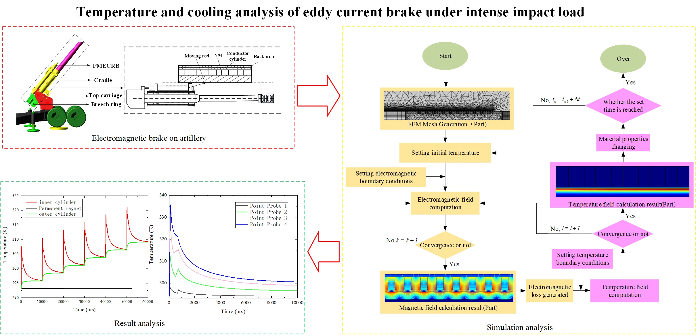
Eddy current brake, due to its non-liquid and friction-free damping form, is widely used in life and military fields, such as, the electromagnetic train brake developed by German railway company [1], the electronic vehicle brake [2], the plate type tuned mass damper (TMD) in China [3], and so on. Our team applied the ECB in the artillery recoil machine as Fig. 1. The shape of the ECB is linear cylindrical and it works in the high speed and intense impact condition.
Fig. 1Electromagnetic brake on artillery
When the ECB works, a lot of heat will be generated due to the law of conservation of energy, so there is many research on the thermal problem of it. Li, X. L. et al. [4] proposed an ECB used in a truck in which both the stator and the excitation coil are water-cooled. They provided theoretical support for the optimal design of the retarder through experiment and simulation. Putra, M. R. A. et al. [5] analysed the performance of the vehicle ECB in different temperature by FEM method. Jin, Y. X. et al. [6] use the computational fluid dynamics and the least square method to propose the correlations for an axial flux permanent magnet ECB. The proposed correlations considered the changes in design parameters and temperatures of the ECB, and the accuracy was verified by the CFD software.
Although there has been many thermal research on the ECB in many case, there is few research on the temperature characteristic of the ECB used in artillery recoil machine under intense impact load. In this case, the heat source of the ECB is instant and intermittent. Because the magnetic material which has been used is sensitive to the temperature, much heat will affect the braking effect, and then affect firing stability and safety. So it is crucial to carry out the thermal analysis on the ECB in artillery recoil before being applied. This paper study the temperature characteristic of this machine with the halbach array, which is an array that generates strong magnetic field. Couple the electromagnetic module and heat transfer module with finite element software to calculate the heat and temperature distribution generated during its work. Subsequently, this paper explores the cooling mode of the ECB according to the temperature rise results and finds a best cooling mode in them to ensure its reliability through comparing cooling effects with different methods.
2. Electromagnetic temperature coupling
2.1. Eddy current calculation
Eddy current is the current loop induced in the conductor due to the change of magnetic field. Current is the result of Faraday’s law of electromagnetic induction. According to Maxwell-Ampere’s law Eq. (1), the electric field is not only generated by electric charge, but also generated by the changing magnetic potential. The high-speed moving permanent magnet group makes the conductor move in the non-uniform magnetic field, resulting in a large change in magnetic flux. The current density and electric field distribution can be calculated:
In the constitutive relationship of materials, the residual prick density model is used for permanent magnets, and the relative permeability model Eq. (2) is used for the inner and outer cylinders:
2.2. Loss and temperature field calculation
The heat of the electromagnetic brake mainly comes from the volume loss generated by the inner cylinder. The heat transfer in the brake is a three-dimensional time dependent process, and its energy conservation equation is Eq. (3):
The heat source is most generated by the electromagnetic loss. There two parts of it. One is the eddy current loss. According to Joule’s law, the loss generated is Eq. (5). Other one is magnetic loss, the loss generated is Eq. (6):
The conductivity of material is dependent on the temperature. This paper uses the linearized resistivity model and their relationship is Eq. (7):
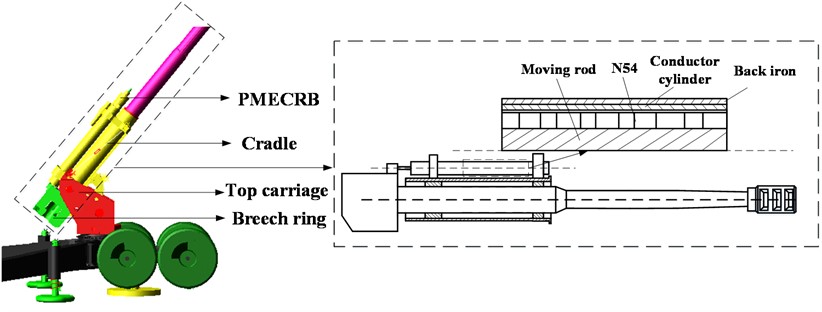
3. Simulation analysis of temperature field of electromagnetic brake
The simulation background is the situation of six rapid-fire rounds of a large gun in 60 seconds. The mesh is show in Fig. 2. Due to the air gap is very thin, the mesh is concentrated in there. Fig. 3 shows the temperature distribution in the first round. The inner cylinder (conductor cylinder) is heated rapidly. Fig. 4 shows the temperature distribution in the last round. Most of the heat flow in the outer cylinder (back iron) and spread in the air. Little of the heat flow in the permanent magnet in short time.
Fig. 2Simulation process
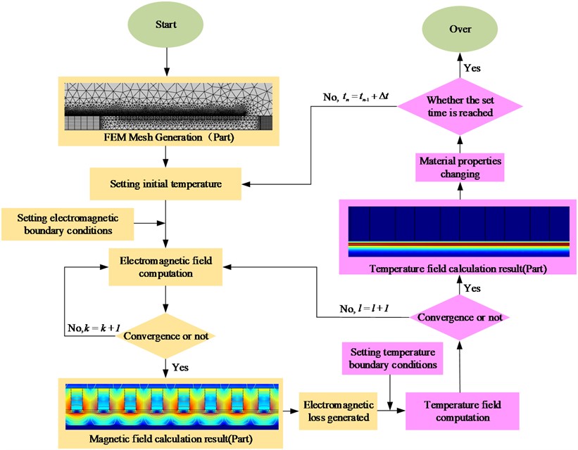
Fig. 3 shows the average temperature of the internal parts of the brake. As shown in the figure, the temperature of the inner cylinder is the most obvious. Each round can increase the temperature by 15 K. Because the heat does not dissipate in time, the average temperature of each cycle can increase by about 2-3K compared with the previous one. The heat of the outer cylinder is conducted by the inner cylinder. Without cooling measures, the temperature rises in a stepwise manner. After each launch, the temperature and the inner cylinder tend to balance. The permanent magnet has an air gap of two millimeters with the inner cylinder, and the air is a poor thermal conductivity material. In a short time of one minute of emission, the heat is basically not transferred to the permanent magnet. The temperature tends to be constant.
Fig. 3Temperature distribution in 500 ms
Fig. 4Temperature distribution in 50500 ms
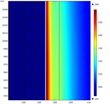
Fig. 5Average temperature of each component
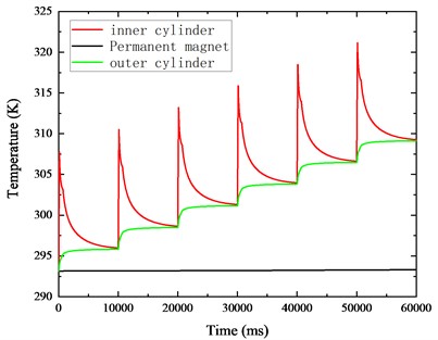
Fig. 6Average temperature in one round
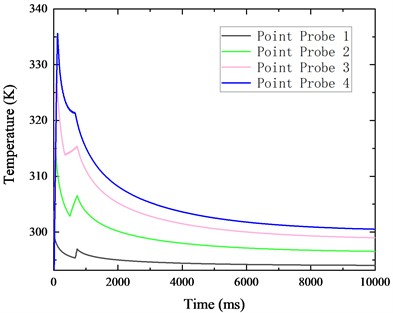
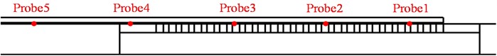
In order to explore the axial distribution of temperature in the ECB, 5 point probes are set to show the different change in different point. The position of the points is show in Fig. 7 and the temperature change curve is show in Fig. 6. The point in the middle of inner cylinder has the highest maximum. The reason is that the permanent magnet always passing by this area and the magnetic induction changing frequently in this place. Because the moving rod will be push back by the recuperator, the permanent magnet passes by the point again and make the temperature rise again. The longer interval between each passing, the more obviously temperature rise.
Fig. 7Position of the point probe
4. Study on cooling measures
Due to the special closed structure of artillery ECB, it is necessary to take cooling measures for it in order to prevent its reliability from decreasing or even failure. The traditional cooling methods include air cooling and water cooling. As Eq. (8), in the case of air cooling, the heat exchange with outside is happening on the surface of the ECB:
Because the internal structure of the brake is closed and the remaining space is small, it is difficult to install the forced air cooling device. However, no matter whether the external cooling is natural or forced cooling, the internal temperature of the ECB cannot be effectively suppressed for a short time, only because the heat cannot transfer to the surface quickly.
So, water cooling should be used to reduce the temperature. It can take out the heat from interior and exchange with outside effectively. According to the temperature distribution from the simulation, this paper assumes that the channels should be concentrated in the middle of the outer cylinder of the brake, as shown in Fig. 8. Combined with the thermal conductivity and uniform convection loss term, the water cooling process can be simulated by defining a generalized heat source as Eq. (9):
The mass flow rate of the coolant used is 1 kg/min. The coolant inlet temperature is 283.15K. The specific heat capacity of the coolant is shown in Table 1. The channel radius is 4.5 mm, 30 liquid cooling channels are arranged.
Table 1Specific heat capacity of the coolant (J/(kg·K))
Medium | Water | Ethanol | Ethylene glycol |
12010.147–80.4078T+0.3098T2 | 4012.27499–18.710T+0.045107T2 | 1071.4679+4.474T |
Fig. 8Channel arrangement

Fig. 9Average temperature comparison
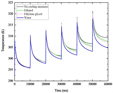
According to Fig. 9, the coolant has a significant effect on the temperature. It has played a role as a cold source, consuming a part of the heat. Compared with the natural cooling outer cylinder, the temperature starts to show a significant downward trend. The cooling effect of different coolants are different. Because the specific heat and thermal conductivity of water are greater than that of ethanol, glycol, etc., it consumes the most heat and has the most obvious cooling effect, while ethanol and glycol have almost the same thermal properties in the current working environment, so the cooling effect is almost the same too.
According to Table 2 and Table 3, in the previous times, the difference of temperature is not obvious and have some error of numerical calculation. But in the next several rounds, the liquid cooling come into play. Both the maximum and minimum temperature have decreased obviously. In the last round, the water cooling makes the maximum temperature decrease about 7.5 K, and makes the end of the temperature decrease about 10.6 K. It effectively reduces the temperature.
Table 2Maximum temperature at each round (K)
Number of times | 1 | 2 | 3 | 4 | 5 | 6 |
No cooling | 340.0 | 347.5 | 354.5 | 360.8 | 367.7 | 375.0 |
Ethanol | 339.7 | 347.5 | 354.0 | 360.5 | 366.6 | 372.9 |
Ethylene glycol | 339.5 | 347.0 | 354.0 | 360.0 | 366.0 | 372.0 |
Water | 339.0 | 346.4 | 352.4 | 357.8 | 362.8 | 367.5 |
Table 3Temperature at end of each round (K)
Number of times | 1 | 2 | 3 | 4 | 5 | 6 |
No cooling | 301.0 | 308.2 | 315.2 | 322.5 | 329.5 | 336.5 |
Ethanol | 301.5 | 308.4 | 314.7 | 321.0 | 327.2 | 333.1 |
Ethylene glycol | 301.4 | 308.0 | 314.2 | 320.5 | 326.3 | 331.9 |
Water | 300.6 | 306.6 | 312.0 | 317.0 | 321.8 | 325.9 |
5. Conclusions
In this paper, the finite element model of the electromagnetic brake is established. Through the electromagnetic and thermal coupling simulation of the eddy current brake, it is found that there is indeed an obvious temperature rise phenomenon when the electromagnetic brake works, which will have a huge impact on the electromagnetic characteristics of the materials inside the brake. The distribution of temperature field during its operation is calculated, and it is found that the temperature will rise about 15 K each round during the launch process. According to the temperature rise distribution law, cooling measures are proposed, and the cooling conditions under different refrigeration fluids are compared. It effectively reduces the temperature of the brake during operation.
References
-
C. Chen, J. Xu, X. Yuan, and X. Wu, “Characteristic analysis of the peak braking force and the critical speed of eddy current braking in a high-speed maglev,” Energies, Vol. 12, No. 13, p. 2622, Jul. 2019, https://doi.org/10.3390/en12132622
-
M. R. A. Putra, M. Nizam, D. D. D. P. Tjahjana, M. Aziz, and A. R. Prabowo, “Application of multiple unipolar axial eddy current brakes for lightweight electric vehicle braking,” Applied Sciences, Vol. 10, No. 13, p. 4659, Jul. 2020, https://doi.org/10.3390/app10134659
-
Z. Wang, Z. Chen, and J. Wang, “Feasibility study of a large-scale tuned mass damper with eddy current damping mechanism,” Earthquake Engineering and Engineering Vibration, Vol. 11, No. 3, pp. 391–401, Sep. 2012, https://doi.org/10.1007/s11803-012-0129-x
-
X. Li, L. Ye, M. Li, and Q. Lv, “Research on temperature and braking performance of water-cooled eddy current retarder,” IEEE Access, Vol. 9, pp. 38991–38998, 2021, https://doi.org/10.1109/access.2021.3058243
-
M. R. A. Putra, D. D. D. P. Tjahjana, M. Nizam, and Z. Arifin, “Performance analysis in eddy current brake at different temperatures using the finite element method,” in 2022 7th International Conference on Electric Vehicular Technology (ICEVT), pp. 169–172, Sep. 2022, https://doi.org/10.1109/icevt55516.2022.9924983
-
Y. Jin, B. Kou, L. Li, and D. Pan, “Fluid flow and thermal analysis of an axial flux permanent magnet eddy current brake,” IEEE Transactions on Vehicular Technology, Vol. 71, No. 1, pp. 260–268, Jan. 2022, https://doi.org/10.1109/tvt.2021.3127693
Cited by
About this article

The authors have not disclosed any funding.
The datasets generated during and/or analyzed during the current study are available from the corresponding author on reasonable request.
The authors declare that they have no conflict of interest.
