Abstract
Aiming at the problem that the vibration calibration accuracy is seriously affected by the additional dynamic magnetic field interference and eddy current effect of the electromagnetic vibration exciters, a suppression method based on magnetic field tracking compensation is proposed. The influence of the dynamic magnetic field interference of the driving current on the total harmonic distortion of the driving coil output electromagnetic force waveform and the characteristics of the eddy current effect are studied. The compensation current set on the central yoke, its direction opposite to the driving current, to realize the dynamic tracking compensation and suppression of the additional dynamic magnetic field interference and eddy current loss of the driving coil, and effectively improve the vibration waveform accuracy and eliminate the temperature change of the working platform caused by eddy current effect. The simulation results show that the eddy current loss may be reduced by 53 % and the total harmonic distortion of the driving electromagnetic force waveform may be reduced by 0.12 % though the method in this paper.
1. Introduction
Vibration sensors are the core component of aviation and aerospace equipment vibration monitoring [1], earthquake and tsunami monitoring and early warning [2], internet of things [3] and other fields. With the development of science and technology, higher requirements are put forward for its vibration signal sensing accuracy. As the calibration equipment, electromagnetic vibration exciters determines the calibration accuracy of vibration sensors, so its performance improvement is urgently.
Among the existing steady-state sinusoidal vibration generation methods, in order to suppress harmonic interference of electromagnetic vibration exciters waveform, mechanical technologies such as air floatation guidance [4] and control methods such as fuzzy control [5] and self-sensing control [6] have been applied. Meanwhile, in order to improve the uniformity of air gap magnetic field distribution, extensive studies have been conducted on magnetic circuit structure [7, 8]. However, most of them focus on static magnetic circuit analysis, and in the actual operation of electromagnetic vibration exciters, the interference magnetic field generated by driving current will also affect the distribution characteristics of air gap magnetic field, and will produce a large number of eddy currents, resulting in the change of calibration environment. The skin effect of the alternating driving current on the surface of the pure ferromagnetic yoke on both sides of the air gap produces eddy current loss, emits heat and conducts it to the vibration sensors, making its calibration result inaccurate. Increasing the air flow around the driving coil to accelerate the heat dissipation can play a certain role, but will bring additional mechanical noise interference. The experimental method of alternating with large and small acceleration can slow down the temperature rise [9, 10], but will reduce the working efficiency of the vibration exciters. Therefore, the problems of temperature change of the working platform and uneven distribution of magnetic field caused by the driving current are still seriously.
In this paper, a magnetic field tracking compensation method for electromagnetic vibration exciters is proposed. By setting the compensation current in the magnetic circuit structure which is opposite to the driving current phase, to effectively suppress the driving current eddy current effect and dynamic magnetic field interference, avoid the heat from eddy current loss to change the calibration environment of vibration sensor, reduce the influence of disturbance magnetic field on vibration waveform accuracy, and verify the effectiveness of the proposed method through simulation.
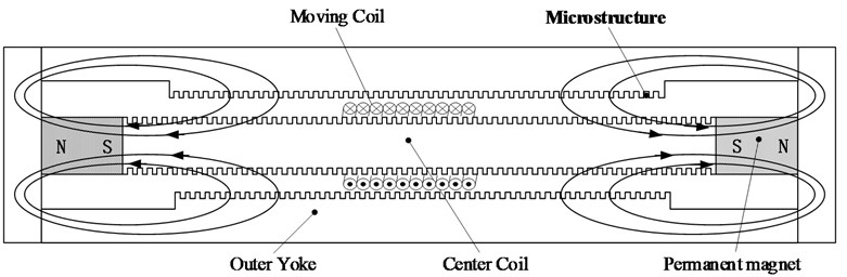
2. Principle of electromagnetic vibration exciters
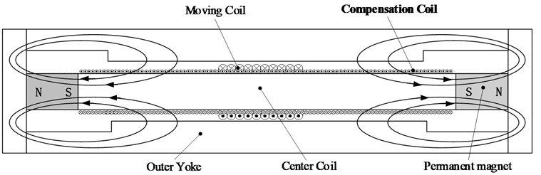
The basic principle of the electromagnetic vibration exciters is shown in Fig. 1. The driving coil is placed in the direction of perpendicular magnetic inductance in a magnetic circuit with uniform magnetic field distribution, and an alternating current is passed through the coil, which is subjected to amperage and produces vibration. Suppose that , and are the mass, stiffness and damping of the moving part, , and are the length, inductance and resistance of the drive coil, and are the current passed into the driving coil and the voltage applied at both ends respectively, , and are the displacement, velocity and acceleration of the moving part relative to the zero point, then the electromechanical coupling equation can be obtained as [4], [11]:
Therefore, the displacement-voltage transfer function of the electromagnetic vibration exciters is:
Fig. 1Basic principle diagram of electromagnetic vibration exciters
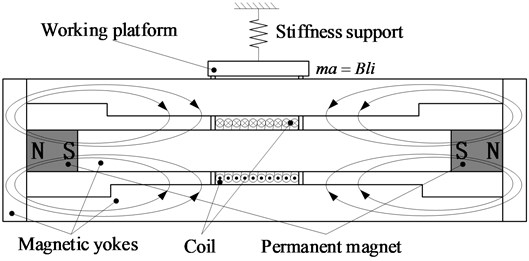
According to Eq. (2), to ensure low-distortion vibration waveform output by the electromagnetic vibration exciters, the magnetic induction intensity of the air gap should be kept constant within the moving range of the driving coil, and the magnetic induction intensity of the air gap magnetic field should be as large as possible to obtain high driving force. However, in actual operation, the disturbing magnetic field generated by the driving current affects the distribution characteristics of the air gap magnetic field, resulting in uneven distribution of air gap magnetic field. In addition, the driving current will generate a large number of eddy currents, leading to changes in the calibration environment. The skin effect of the alternating driving current on the surface of the pure ferromagnetic yoke on both sides of the air gap leads to eddy current loss, which emits and conducts heat to the vibration sensor in calibration, causing temperature changes and misalignment of the calibration results [10]. Therefore, it is necessary to suppress the eddy current loss of the driving current to avoid changes in the sensor calibration environment.
3. Suppression method of drive current disturbance magnetic field and eddy current loss
3.1. Model building
In the current research on steady-state sinusoidal vibration generation methods, most of the research on the uneven distribution of magnetic field with long air gap focuses on the analysis of magnetic circuit structure, and quite mature research results have been obtained. However, the disturbing magnetic field generated by the driving current also affects the distribution characteristics of the air gap magnetic field and influences the distortion of the vibration waveform. The precision characteristics of high-sensitivity sensors also need strict requirements for their operating environment, but eddy current losses from alternating drive currents can cause changes in ambient temperature, making the calibration result inaccurate with interference factors. Therefore, in order to analyze the electromagnetic effect of the driving current, a closed-double-magnetic circuit of the electromagnetic vibration exciters is established as shown in Fig. 2.
Fig. 2The model of closed-double-magnetic circuit
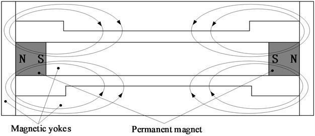
Fig. 3The magnetization characteristic curve of DT4C
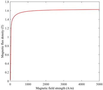
The relative permeability of soft magnetic materials used in the magnetic yoke directly affects the uniformity of magnetic induction intensity distribution in the air gap. Therefore, the electromagnetic pure iron material named DT4C is selected, which is characterized by high saturation magnetic induction intensity, high permeability and low coercivity, and the maximum relative permeability up to 15000. The magnetization characteristic curve is shown in Fig. 3. NdFe32 permanent magnet material is selected for the permanent magnet, and the magnetic poles of the two permanent magnets are arranged opposite to each other. The driving coil is made of copper with good conductivity and is wound evenly on the moving coil skeleton, with 20 turns and a thickness of 5 mm.
3.2. Transient magnetic field simulation
In order to study the electromagnetic response of the drive current during the actual sinusoidal moving of the electromagnetic vibration exciters, the transient magnetic field simulation was established by maxwell finite element simulation software. Specifically, the vibration frequency is 10 Hz, the displacement amplitude is 500 mm, and the driving current is the same frequency and phase with the vibration displacement, and the amplitude are 1 A, 2 A and 4 A, respectively. According to the simulation, the magnetic induction intensity distribution of the electromagnetic drive structure is shown in Fig. 4, the output force waveform of the drive coil is shown in Fig. 5(a), the eddy current loss is shown in Fig. 5(b), and the statistical results are shown in Table 1.
Fig. 4The magnetization characteristic curve of DT4C
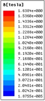
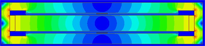
Fig. 5Drive current electromagnetic response simulation results
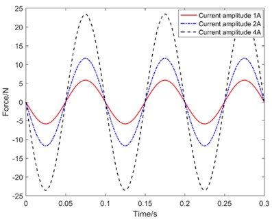
a) Drive coil output force waveform
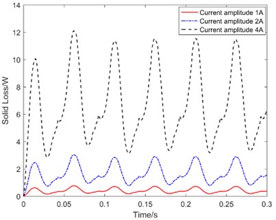
b) Eddy current loss waveform
Table 1Simulation results statistics
Drive current amplitude (A) | Eddy current loss RMS (W) | Drive coil output force RMS (N) | Drive coil output force total harmonic distortion (%) |
1 | 0.44 | 4.05 | 0.36 |
2 | 1.7 | 8.11 | 0.49 |
4 | 7.17 | 16.26 | 0.73 |
As can be seen from Figs. 4-5 and Table 2, under the same vibration frequency, eddy current loss increases by the square of the driving current growth multiple, and emitting a large amount of heat. When the output force of the driving coil and the current value increase by the same factor, the harmonic distortion of the output driving force also increases, that is, the effect of the alternating drive current on the uniformity of the air-gap magnetic field distribution worsens as the drive current increases. Therefore, it is necessary to suppress the electromagnetic response of the drive current, reduce the heat emitted by eddy current losses to avoid the thermal disturbance and thermal deformation problems, reduce the dynamic magnetic field interference, ensure the high uniformity of the air gap magnetic field distribution during exciters operation, and achieve the approximately ideal linear electromagnetic driving force characteristics.
3.3. Drive current electromagnetic response suppression method
As shown in Fig. 6, put forward two methods to suppress electromagnetic response. As shown in Fig. 6(a) method Ⅰ with microstructure is to add microstructure on the magnetic yoke surface adjacent to the air gap, to suppress the generation of induced current skin effect, thus effectively reduce the eddy current loss, but machining microstructures is difficult, and in the process of machining, it is inevitable to reduce the magnetic yoke permeability. At the same time, the microstructure also changes the magnetic line path, making the distribution of air gap magnetic field more uneven. Method Ⅱ with magnetic field tracking compensation shown in Fig. 6(b) sets the magnetic field compensation current on the central yoke, in which he current passing through is in the opposite direction to the drive current, their effect on the magnetic circuit is also opposite, which can effectively suppress the generation of eddy currents and greatly reduce the heat emitted by eddy current loss, and the magnetic field formed by the compensation current will reduce the influence of the interference magnetic field on the main magnetic field distribution. The drive current electromagnetic response is compensated by synchronous tracking, effectively solving the problem of large distortion of the standard vibration waveform output from the electromagnetic vibration exciters caused by the drive current electromagnetic response, so that the actual performance index of the magnetic circuit structure has a high consistency with the theoretical design results and realizes high design accuracy.
Fig. 6Electromagnetic response suppression method
a) Method Ⅰ with microstructure
b) Method Ⅱ with magnetic field tracking compensation
4. Simulation verification
Method Ⅱ with magnetic field tracking compensation as shown in Fig. 6(b) is used to simulate the transient magnetic field of the center yoke after adding the compensation coil. The number of compensation coil is 920 turns, and its wire diameter is 1.5 mm. The moving parts vibrate sinusoidal displacement with an amplitude of 500 mm and a frequency of 10 Hz, the current of the driving coil is sinusoidal current with amplitude of 10 A and frequency of 10 Hz, the data sampling frequency is 5000 Hz, take 2 cycles of data. The compensation current is set to be a sinusoidal waveform of different amplitudes, with a frequency of 10 Hz and in reverse phase with the drive current. The relationship between the eddy current loss of the drive coil, the total harmonic distortion of the force waveform and the compensation current obtained by simulation is shown in Fig. 7, and the eddy current loss waveform generated by the drive current at different compensation currents is shown in Fig. 8.
Fig. 7The relationship between the eddy current loss of the drive coil, the total harmonic distortion of the force waveform and the compensation current
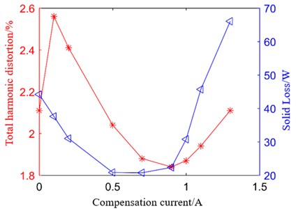
Fig. 8The eddy current loss waveform
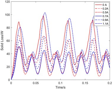
As can be seen from Fig. 7, without compensation current, the total harmonic distortion of the force waveform of the drive coil is about 2.1 %, which decreases and then increases after adding the compensation current, where the distortion of the force waveform drops to a minimum of 1.84 % when the amplitude of the compensation current is 0.9 A, effectively reducing the influence of the drive current on the air gap magnetic field distribution. From Fig. 7 and Fig. 8 is easy to know, no additional current, the eddy current loss generated by the drive current is about 44.19 W (RMS), with the increase of the compensation current, the drive coil eddy current loss gradually reduced, but when increased to a certain value, the resulting eddy current loss will gradually exceed the drive current, so should take the appropriate compensation current value, in its amplitude of 0.6 A, the lowest eddy current loss is about 20.75 W (RMS), which is reduced by 53 %, and the distortion of the driving force waveform is about 1.99 %, which is reduced by 0.12 %. At this time, the eddy current loss is minimized and the harmonic distortion is small, fully verifying the superiority of the additional magnetic field real-time tracking to compensate for the influence of the drive current.
5. Conclusions
This paper proposed a magnetic field tracking compensation method for electromagnetic vibration exciters, which effectively suppresses the drive current eddy current effect and dynamic magnetic field interference. The magnetic circuit structure is equipped with a compensating current of opposite phase to the driving current, which exhibits an electromagnetic response opposite to the driving current, avoiding the influence of heat emitted by eddy current losses on the calibration environment of the vibration sensors, and reducing the influence of the disturbing magnetic field on the accuracy of the vibration waveform. Simulation results show that the magnetic field tracking compensation method may reduce eddy current loss by 53 % and reduce the total harmonic distortion of the drive electromagnetic force waveform by 0.12 %.
References
-
Q. Z. Wang, B. Liu, and W. B. Song, “Aerospace failure and survey of prediction and control technique of dynamic environment,” Environmental Technology, Vol. 4, pp. 1–6, 1995.
-
A. K. Sharma, R. N. Haridas, A. V. Patil, and R. V. Bhonsle, “Study of ultra low frequency signals (0.01-10 Hz) associated with moderate earthquake occurred in Koyna region using induction type magnetic sensor,” in 2011 30th URSI General Assembly and Scientific Symposium, pp. 1–4, Aug. 2011, https://doi.org/10.1109/ursigass.2011.6051036
-
T. Shimoda, W. Kokuyama, and H. Nozato, “Primary calibration system for digital accelerometers,” Metrologia, Vol. 58, No. 4, p. 045002, Aug. 2021, https://doi.org/10.1088/1681-7575/ac0403
-
W. He, X. Zhang, C. Wang, R. Shen, and M. Yu, “A long-stroke horizontal electromagnetic vibrator for ultralow-frequency vibration calibration,” Measurement Science and Technology, Vol. 25, No. 8, p. 085901, Aug. 2014, https://doi.org/10.1088/0957-0233/25/8/085901
-
K. P. S. Rana, “Fuzzy control of an electrodynamic shaker for automotive and aerospace vibration testing,” Expert Systems with Applications, Vol. 38, No. 9, pp. 11335–11346, Sep. 2011, https://doi.org/10.1016/j.eswa.2011.02.184
-
X. Zhang, W. He, and C. Wang, “Self-sensing waveform control for a low-frequency electromagnetic vibrator,” IEEE/ASME Transactions on Mechatronics, Vol. 22, No. 2, pp. 785–793, Apr. 2017, https://doi.org/10.1109/tmech.2016.2635260
-
W. He, C. Wang, M. Yu, R. Shen, and S. Jia, “Closed-double-magnetic circuit for a long-stroke horizontal electromagnetic vibration exciter,” IEEE Transactions on Magnetics, Vol. 49, No. 8, pp. 4865–4872, Aug. 2013, https://doi.org/10.1109/tmag.2012.2225109
-
J. Cui, Z. He, and J. Tan, “Proposal and analysis of three closed double magnetic circuits to obtain a very long stroke for electrodynamic force generators,” Sensors and Actuators A: Physical, Vol. 263, pp. 122–130, Aug. 2017, https://doi.org/10.1016/j.sna.2017.05.049
-
G. P. Ripper, R. S. Dias, and G. A. Garcia, “Primary accelerometer calibration problems due to vibration exciters,” Measurement, Vol. 42, No. 9, pp. 1363–1369, Nov. 2009, https://doi.org/10.1016/j.measurement.2009.05.002
-
G. P. Ripper, R. S. Dias, and G. A. Garcia, “Interferometric evaluation of the sensitivity of accelerometers to differential heating,” in Eighth International Conference on Vibration Measurements by Laser Techniques: Advances and Applications, Jun. 2008, https://doi.org/10.1117/12.803342
-
R. S. Koyanagi, “Development of a low-frequency-vibration calibration system,” Experimental Mechanics, Vol. 15, No. 11, pp. 443–448, Nov. 1975, https://doi.org/10.1007/bf02410344
About this article

This research work is supported by the National Natural Science Foundation of China of No. 52075133.
