Abstract
To analyze accurately the temperature variation of permanent magnet synchronous motor, a bidirectional magnetic-thermal coupling method is proposed. Firstly, a two-dimensional magnetic field model of permanent magnet synchronous motor was built in Ansoft Maxwell, and the magnetic flux density, magnetic line distribution and radial air gap magnetic flux of the motor have been simulated. Secondly, the calculated winding copper loss, core loss and permanent magnet eddy current loss were coupled into the temperature field of ANSYS Workbench as heat source, and the transient temperature field of each part of the motor was studied. Finally, the electromagnetic and temperature fields of the motor were analyzed and calculated at the same time, and were mutually updated based on their iterations. The process was repeated until stable magnetic and temperature fields were generated. The results showed that the bidirectional coupling method took into account the influence of motor temperature rise on electromagnetic field, and the temperature rise prediction was more accurate than the unidirectional coupling method.
Highlights
- The paper introduces various losses into the three-dimensional magnetic-thermal coupling model of the motor, solves and simulates the temperature field of the motor, and captures the hot spots of the motor.
- The paper puts forward a bidirectional coupling research method based on the research of motor magnetic-thermal unidirectional coupling, the bidirectional coupling method took into account the influence of motor temperature rise on electromagnetic field, and the temperature rise prediction was more accurate than the unidirectional coupling method.
- The method considers not only the influence of the motor magnetic field on the temperature field, but also temperature field variations caused by the interaction between the motor and the temperature field, which has strong application and popularization value.
1. Introduction
Motor is the key component of new energy vehicles. Compared with the traditional drive motor, the permanent magnet synchronous motor (PMSM) is small in size and light in weight, but has high efficiency and power density. At present, many electric vehicles use PMSM as the drive motor. However, PMSM will produce various losses during operation, including winding copper loss, permanent magnet eddy current loss and stator and rotor iron loss [1]. The loss generated during the motor operation will be released from the inside in the form of heat, causing gradual rise of the motor temperature. However, the permanent magnet of PMSM has a critical temperature point. When the temperature reaches the critical temperature point, the magnetism of the permanent magnet will decrease or even will be lost completely, which will seriously affect the motor performance, even lead to a motor failure, because it is a potential safety hazard [2]. Therefore, accurate analysis of the loss and temperature field produced during the motor operation is the guarantee for the safe and effective operation of the motor.
At present, there are three main calculation methods for motor temperature field: simplified formula method, equivalent thermal network method and finite element method. Simplified formula method can be used to simply calculate the temperature rise and loss of motor, which is the simplest method to study the temperature field of motor [3]. This method is only valid when the internal temperature difference of the motor is small, the calculated temperature rise has poor accuracy. The equivalent thermal network method adopts the principle of graph theory, takes the thermal circuit as the basis and uses the network topology to calculate the motor temperature field [4]. The equivalent thermal network method only allows getting the average temperature of a certain part of the motor, but cannot accurately allow capturing the position of the hot spots of the motor, which is an important factor affecting the smooth motor operation. Zhu Z. Y. et al. [5] calculated the temperature rise of the permanent magnet synchronous motor by the equivalent thermal network method, and obtained the average temperature rise of each subdivision inside the motor, however, the position of the motor hot spot could not be accurately located. Tan D. et al. [6] studied the temperature rise of the submersible motor, calculated the equivalent thermal resistance in the model by using the improved empirical formula and established the equivalent thermal network model of the motor, but it failed to locate accurately the hot spot inside the motor. Ding S. Y. et al. [7] studied the temperature rise of the stress motor and proposed a thermal equivalent network method for calculating the temperature rise of the stator winding, but only indicated the location of the hot spots in the stator winding and did not specify the location of other hot spots in the motor.
The finite element method is the most commonly used method to calculate the temperature rise of the motor at present. It can complete the unidirectional and bidirectional solution of the electromagnetic and temperature fields of the motor, as well as realize the coupling calculation for the stress field, noise and temperature field of the motor [8]. Using the finite element method to study the temperature field of the motor, it is possible to analyze the distribution of the whole temperature field and the location of hot spots with high accuracy. Fan X. G. et al. [9] used the field-circuit coupling method to design and analyze the control strategy of electric vehicle hub motor, and demonstrated the feasibility of applying the field-circuit coupling method in the motor control circuit, but his study considered only the magnetic field, but not the temperature field. Chen Q. P. et al. [10] used the unidirectional magnetic-thermal coupling method to analyze the temperature field of electric vehicle hub motor under different operating conditions, and the analysis results had certain accuracy. Wang X. Y. et al. [11] established a field-circuit coupling model combining the finite element motor body model with the control circuit model by using the time-stepping finite element method, and simulated and calculated the motor losses under different operating conditions, but he did not couple the losses into the temperature field of the motor. Li L. Y. [12] used the time-stepping finite element method to optimize the operating efficiency of the permanent magnet synchronous motor under various operating conditions, and showed the application of finite element method in motor efficiency calculation.
To popularize the application of the permanent magnet synchronous motor in new energy vehicles and improve the performance of PMSM for electric vehicles, aiming at the influence of motor losses on temperature rise, this paper puts forward a bidirectional coupling research method based on the research of motor magnetic-thermal unidirectional coupling. It introduces various losses into the three-dimensional magnetic-thermal coupling model of the motor, solves and simulates the temperature field of the motor, and captures the hot spots of the motor. Compared with the unidirectional magnetic-thermal coupling method, it can improve the accuracy of calculating the motor loss and temperature rise. This method considers not only the influence of the motor magnetic field on the temperature field, but also temperature field variations caused by the interaction between the motor and the temperature field, which has strong application and popularization value.
2. Motor magnetic field analysis
2.1. Motor parameters and finite element model
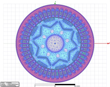
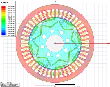
A vehicle hub motor (permanent magnet synchronous motor, PMSM) was taken as the research object, its parameters were detailed in Table 1. Ansoft Maxwell software is used for modeling and subsequent electromagnetic simulation. The motor model is a two-dimensional model, as shown in Fig. 1. The grid division results are shown in Fig. 2. According to Fig. 2, the grid division is relatively uniform on the whole. But, in some places where the magnetic field varies greatly, and the magnetic field is relatively strong, thus creating an air gap between the rotor and the stator, the grid density shall be increased to improve the accuracy.
Table 1Main technical parameters of motor
Parameter | Numerical value | Parameter | Numerical value |
Rated power | 45 kw | Number of poles | 8 |
Number of stator slots | 48 | Rated speed | 3000 r/min |
Outer diameter of stator | 198 mm | Efficiency | 97.7 % |
Inner diameter of stator | 132 mm | Inner diameter of stator | 44.45 mm |
Gas gap length | 1 mm | Core length | 160 mm |
Fig. 1Two-dimensional motor model
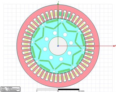
Fig. 2Grid division of two-dimensional motor model
2.2. Mathematical model of motor magnetic field
Maxwell's equation is the basis of electromagnetic field theory and numerical analysis of engineering electromagnetic field. It is composed of Ampere Loop Law, Faraday Electromagnetic Induction Law, Gauss Electrification Law and Gauss Flux Law respectively, and its integral form can be expressed as follows:
where: is the magnetic field intensity; is the boundary of curved surface ; is the conduction current density vector; is the magnetic flux density; is the electric field intensity; is the magnetic induction intensity; is the charge bulk density, and is the volumetric area surrounded by the closed curved surface .
Maxwell's equations have its differential form in addition to integral form, which is:
The relation among the field quantities , , and is determined by the characteristics of the medium. Generally, for linear medium, the relation is:
where is the dielectric constant of the medium, F/m; is the permeability of the medium, H/m; is the conductivity of the medium, S/m; for isotropic media, , and are scalars; for anisotropic media, they are tensors.
2.3. Magnetic field simulation calculation
When the hub motor works at the rated speed and rated load in a transient state, the two-dimensional magnetic flux cloud map and magnetic force line distribution map at 0.5 ms are selected for the analysis, which results are shown in Fig. 3 and Fig. 4. According to the cloud chart of magnetic flux density shown in Fig. 3, the magnetic flux density of the motor is the highest in the yoke part, and it is the lowest in the core part. According to the distribution diagram of magnetic lines of flux shown in Fig. 4, the distribution of magnetic lines of flux is uniform, which indicates that the motor itself is designed reasonably.
Fig. 3Cloud chart of magnetic flux density
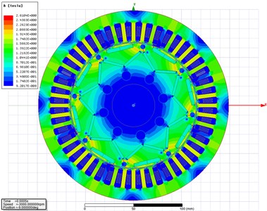
Fig. 4Distribution diagram of magnetic lines of flux
2.4. Air gap magnetic density analysis
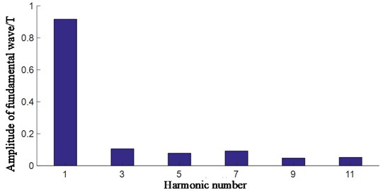
The energy conversion between the motor stator and rotor is accomplished in the air gap. Therefore, the research of the air gap is vitally important for the motor performance analysis. Usually, a magnetic leakage takes place, and it has a great influence on the AC and DC axis reactance of the motor, and then affects the heating condition of the motor[13]. In this paper, the field calculator in ANSYS Maxwell was used to solve the radial magnetic density of the permanent magnet synchronous motor, and the calculation results shown in Fig. 5 were obtained. According to Fig. 5, there are 48 flux density peaks at 360° circumference, which is related to the number of stator slots of the motor. Local cavities and peaks are caused by the slotting effect. By Fourier decomposition of radial magnetic density, the fundamental amplitude of radial magnetic density of air gap is obtained as shown in Fig. 6, and its maximum value is 0.9T. For the permanent magnet synchronous motor, it is generally 0.7T to 1.05T. Thus, it can be seen that the design of this motor meets the requirements.
Based on the above magnetic field simulation and analysis, it shows that the design of the target motor in this paper is reasonable, and the established model is credible, which lays a solid foundation for the next step of temperature field analysis.
Fig. 5Radial magnetic density of air gap
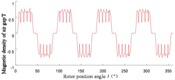
Fig. 6Amplitude of fundamental wave of radial magnetic density of air gap
3. Temperature field analysis
3.1. Mathematical model of thermal field
According to the law of energy conservation and the basic law of heat transfer, for isotropic media, the thermal conductivity is constant. In a rectangular coordinate system, the transient temperature field in the motor can be obtained from the governing differential equation of thermal conductivity [14]:
where, is the temperature function changing with time ; and are the thermal conductivity of the material along the x and y directions, respectively, and = ; is the heat generated per unit area; is the motor material density; is the specific heat of the material; and are the conduction rates of materials along the and directions, respectively. For steady-state temperature field, temperature does not change with time , that is, 0. So, Eq. (4) can be expressed as:
The thermal motor analysis considered the heat conduction and convection inside the motor and the heat convection on the external surface. According to the heat transfer principle and motor knowledge, the corresponding boundary conditions are established as follows:
where, is the hot edge interface; is the heat flux density, when 0, it means that the motor system does not exchange heat with the outside world, which is also known as adiabatic boundary condition; represents the normal direction outside the boundary, that is, the direction of heat flux ; is the thermal conductivity (thermal conductivity) of the object; is the heat release coefficient (heat exchange coefficient) between the medium and the object.
3.2. Motor loss analysis
The motor loss during operation is the main cause of its temperature rise, so it is vitally important to analyze the motor loss accurately. The motor losses during operation mainly include: winding copper loss, stator and rotor iron loss, permanent magnet eddy current loss and mechanical loss [15]. Basically, these losses will be converted into heat energy, which will be transferred among the components inside the motor, and thus it affects the distribution of temperature field inside the motor. The total loss of the motor is:
where, is the winding copper loss; is the core loss; is the eddy current loss of permanent magnet; is the mechanical loss.
3.2.1. Copper loss
The winding copper loss of the motor is caused by the motor current, which is mainly related to the number of winding phases, the effective current and resistance values of the winding. If to involve the Joule-Lenz law, the winding copper loss can be expressed as:
where, is the circulation coefficient between parallel strands; is the number of wires in terms of the coil width; is the coil width; is the slot width; is the rated frequency of motor; is the motor phase current; is the winding resistance.
Because of the high power density of the permanent magnet synchronous motor, the temperature rises rapidly during the motor operation, and this process leads to the increase of winding resistance. The relation between resistance and winding temperature is as follows:
where, is the initial ambient temperature; is the winding resistance value at temperature , which can be directly calculated by material properties and winding design; is the winding resistance at temperature ; is the temperature coefficient of the winding resistance at temperature .
3.2.2. Iron loss
The motor stator and rotor will produce iron loss under the excitation of sinusoidal alternating magnetic field, which includes hysteresis loss, eddy current loss and residual loss [16]. Iron loss is closely related to the magnetic field inside the motor, and its calculation is more complicated than other losses. It is influenced by the processing technology of stator and rotor and ferromagnetic materials[17]. The iron loss in the motor is mainly produced when the main magnetic field changes in the iron core, and this change includes hysteresis loss and eddy current loss. Hysteresis loss is caused by alternating the magnetization and rotating the magnetic field, while the eddy current loss is caused by current induced by changing magnetic field.
Core loss per unit weight can be expressed as:
where, and are hysteresis constant and eddy current constant, respectively; generally, = 40 to 55, and = 0.04 to 0.07; is the Steinmetz coefficient related to the laminated material, and the motor generally takes 1.8-2.0; is the synchronous angular velocity; is the magnetic flux density.
3.2.3. Permanent magnet eddy current loss
Permanent magnet placed inside the rotor have poor heat dissipation and are prone to demagnetization at a high temperature. Therefore, it is necessary to calculate accurately the eddy current loss of permanent magnet to prevent it from affecting the motor operation. According to the law of magnetic induction, when the external magnetic field varies, the induced electromotive force and current in a vortex shape around the magnetic flux will be generated in the permanent magnet, and the eddy current loss generated can be expressed as follows:
where, is the axial length of the permanent magnet; is the radial width of the permanent magnet; is the volume of the permanent magnet; is the proportional constant of electromotive force; is the alternating frequency of magnetic field; is a permanent magnet; is the resistivity of the permanent magnet.
3.2.4. Mechanical loss
The mechanical loss of the motor is mainly wind resistance loss and bearing loss, and the calculation formula is:
where, is the wind resistance friction coefficient; is the axial Reynolds number; is the radial Reynolds number; is the rotor radius; and is the rotor length; is gas density; is the rotational angular velocity of the motor; is the bearing diameter; is the bearing coefficient.
3.3. Simulation analysis of magnetic-thermal coupling temperature field
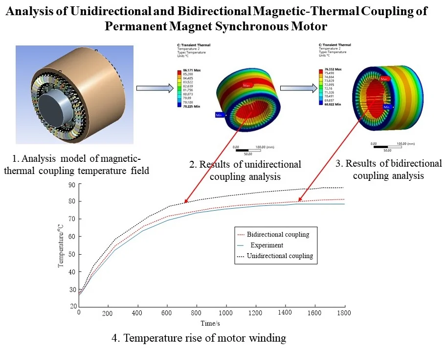
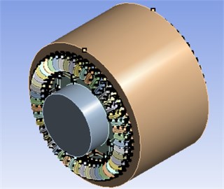
In this section, a three-dimensional model of the motor is used to build a magnetic-thermal coupling model, which can help analyze the temperature field of the motor in a more comprehensive manner than the traditional two-dimensional model of the motor. Fig. 7 is a three-dimensional magnetic-thermal coupling simulation model of PMSM, which consists of stator, rotor, permanent magnet, winding and rotating shaft. By using the formula mentioned above, all kinds of losses of the motor are calculated, and these losses are introduced into the three-dimensional model of the motor, that is, the magnetic-thermal coupling model of the motor is formed. Then, this coupling model can be used to analyze the motor temperature field. The simulated operating condition: the motor speed is set at 1500 rpm and the load is set at 50 N·m.
Fig. 7Analysis model of magnetic-thermal coupling temperature field
3.3.1. Thermal conductivity coefficient
For the calculation of motor temperature field, it is very important to set motor materials. The properties of motor materials will change with the increase of motor temperature, which will further affect the motor operation. At the room temperature 25 ℃, the thermal conductivity of common motor materials is shown in Table 2.
Table 2Thermal conductivity coefficient of motor materials
Motor structure | Thermal conductivity (W/(m·k)) |
Silicon steel sheet (DW310-35) | 43 |
Permanent magnet (NdFe35) | 8.9 |
Copper conductor | 416 |
Axle | 61 |
Air | 0.026 |
Insulation materials | 0.31 |
(1) Equivalent thermal conductivity coefficient of insulating materials.
The calculation of thermal conductivity coefficient of insulating materials is complicated, and need to be assumed: the insulation layer in the winding part is evenly distributed, and the wires are also evenly distributed in the winding group, regardless of the temperature difference between the internal wires when the motor is running [18]. Then the calculation expression of the thermal conductivity coefficient of the insulation material inside the motor is as follows:
where, is the equivalent thermal conductivity coefficient of insulating materials; is the thermal conductivity coefficient of various materials; is the equivalent thickness of insulating materials.
(2) Equivalent thermal conductivity coefficient of air gap.
When calculating the thermal conductivity coefficient of the air gap, the following conditions are assumed: the inner surface of the motor stator and the outer surface of the rotor are ideal cylindrical surfaces, without considering the influence of machining. Then the Reynolds number in the air gap is calculated as follows:
where, is the circumferential speed of the outer circumference of the rotor (m/s); is the air gap length (m); is the air viscosity (m2/s).
The expression of critical Reynolds number is as follows:
where, is the inner radius of the motor stator (m).
When determining the equivalent thermal conductivity coefficient of the air gap, it is also necessary to determine whether the air in the air gap is in a laminar or turbulent state. When , the air in the air gap is in the laminar state, and the equivalent thermal conductivity coefficient of the air gap is equal to that of air. Otherwise, the air in the air gap is in the turbulent state. The thermal conductivity coefficient of the air gap is calculated by the following formula [19]:
where, is the ratio of the outer diameter of the rotor to the inner diameter of the stator.
3.3.2. Convection coefficient of heat transfer boundary
The air gap has a great influence on the heat transfer among the components inside the motor, because heat convection takes place between the air gap and the outer surface of the rotor, the inner surface of the stator and the slot wedge. Heat transfer also exists between the outer surface of the stator and the casing. So, the coefficient of convection between these contact surfaces has certain influence on the temperature rise of the motor.
The coefficient of convection between the inner surface of the air gap and the outer surface of the rotor is [20]:
where, is the rotational linear velocity of the rotor surface.
The coefficient of convection between the outer surface of the air gap, the inner surface of the stator and the slot wedge is [20]:
Assuming that the temperature of the casing and the external temperature are both initial temperatures, the coefficient of convection between the stator outer surface and the casing is [20]:
where, is the coefficient of convection of the heating element at the initial temperature; is the velocity of the outside air flow, and is the air flow efficiency at the initial temperature; is the initial temperature of casing and air.
If the casing is naturally cooled, the coefficient of convection between the outer surface of the stator and the casing is [20]:
3.3.3. Unidirectional coupling analysis
In this section, the unidirectional coupling method is used to carry out the magnetic-thermal coupling analysis of permanent magnet synchronous motor. The unidirectional coupling belongs to sequential coupling.
Firstly, the magnetic field distribution in a two-dimensional model of permanent magnet synchronous motor is simulated by Ansoft Maxwell, and the winding copper loss, core loss and permanent magnet eddy current loss of hub motor are calculated. Then, these losses are indirectly coupled into the ANSYS workbench temperature field as a heat source for analysis. Finally, the temperature rise of the motor is solved. Fig. 8 contains the result of unidirectional coupling analysis.
Fig. 8Results of unidirectional coupling analysis
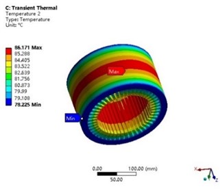
a) Stator
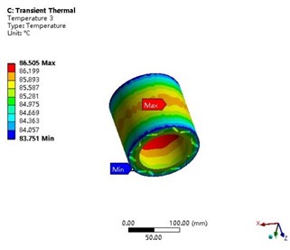
b) Rotor
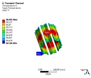
c) Permanent magnet
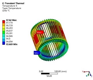
d) Winding
3.3.4. Bidirectional coupling analysis
Bidirectional coupling analysis is developed on the basis of unidirectional coupling method. The electromagnetic and temperature fields of motor are analyzed and calculated in parallel and are updated iteratively. Firstly, the material properties of each part of the motor are set in Ansoft Maxwell. Then the loss of each part of the motor is introduced into the temperature field as a heat source to calculate the motor temperature rise. Finally, the feedback iterator is added in the ANSYS Workbench, and the calculated temperature of each motor component is imported into the electromagnetic calculation unit. The feedback iterative calculation is carried out repeatedly until the calculation result of motor temperature and loss differs by less than 1 %. Fig. 9 contains the result of bidirectional coupling analysis.
Fig. 9Results of bidirectional coupling analysis
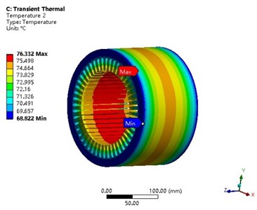
a) Stator
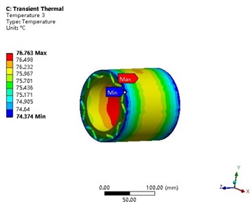
b) Rotor
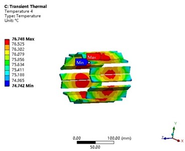
c) Permanent magnet
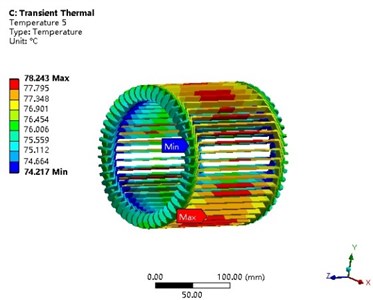
d) Winding
The simulation results of unidirectional coupling and bidirectional coupling are shown in Table 3. According to Table 3, on the whole, the temperature calculated by the unidirectional coupling method is higher than that calculated by the bidirectional coupling method, but the temperature variation range obtained by the two analysis methods does not obviously increase or decrease significantly.
Table 3Temperature comparison of various parts inside the motor
Temperature change range | Unidirectional coupling | Bidirectional coupling |
Stator | 78.2 ℃-86.1 ℃ | 68.8 ℃-76.3 ℃ |
Rotor | 83.7 ℃-86.5 ℃ | 74.3 ℃-76.7 ℃ |
Permanent magnet | 74.1 ℃-86.4 ℃ | 74.7 ℃-76.7 ℃ |
Winding | 83.6 ℃-87.6 ℃ | 74.2 ℃-78.2 ℃ |
According to Fig. 8 and Fig. 9, the highest motor temperature usually appears in the middle part. The highest motor temperature appears in the winding, because of poor heat dissipation in the winding. There are two main ways for winding to dissipate the heat. One consists in dissipating the heat from the end face of winding, which has a small heat dissipation area. The other one is to transfer the heat out through the stator and then through the shell. The heat dissipation path is too long, and the heat transfer coefficient of the insulation layer of the motor winding is relatively small. Thus, it is difficult to transfer the heat out, so the motor winding temperature is higher than that of other parts. At the same time, it can be seen that the temperature variation range of the stator is larger than that of other parts of the motor because of the contact between the stator and the winding, and the closer contact between the stator and the external environment, so the heat dissipates faster than the motor rests.
4. Experiment
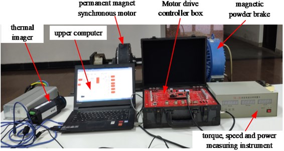
To verify the accuracy and error of the simulation results of unidirectional coupling and bidirectional coupling methods, a motor test bench shown in Fig. 10 was built. The motor test bench includes upper computer, motor drive controller, permanent magnet synchronous motor, magnetic powder brake, torque, speed and power measuring instrument, power battery and other devices. CCS3.3 software is to be run in the upper computer, connecting the motor drive controller with the upper computer through the emulator, opening and compiling the motor control model under the environment of MATLAB/Simulink. And the cSPACE experimental device is used to generate automatically the C language code, through the parameter adjustment controlling the operation of the permanent magnet synchronous motor. Finally, a thermal imager is used to observe the temperature rise of the motor within 1800 s. The statistical results are shown in Fig. 11. Experimental conditions: the motor speed is set at 1500 rpm; the motor operates with a torque of 50 N·m.
Fig. 10Motor test bench
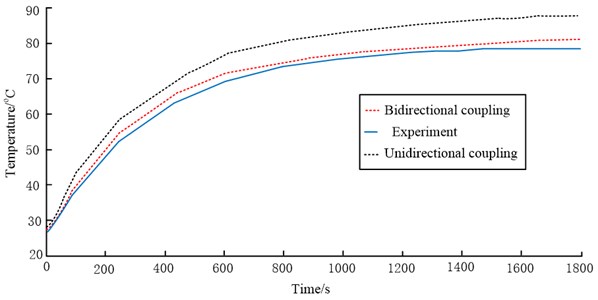
According to the temperature rise curve of the motor winding in Fig. 11, the simulation data of unidirectional and bidirectional coupling are larger than the experimental data. But compared with the simulation method of unidirectional coupling, the simulation method of bidirectional coupling is closer to the experimental results, with less than 5 % error, which shows that the accuracy of bidirectional coupling method is better. The statistical temperature rise trend of stator, rotor and permanent magnet is similar to that of winding, so no statistical curve is given here additionally.
The simulated temperature rise curve is higher than that measured by experiment during operation. The possible reason is that the external environment temperature is low, and the motor dissipates heat quickly in the natural environment. Overall, the results of bidirectional coupling simulation are very close to the experimental results, which indicates that the simulation method proposed in this paper can approach the actual temperature rise of the motor more closely.
Fig. 11Temperature rise of motor winding
5. Conclusions
The Ansoft Maxwell and ANSYS workbench was used to create a magnetic-thermal coupling co-simulation model of permanent magnet synchronous motor to make a unidirectional and bidirectional coupling analysis. Based on experiments and simulations, the following conclusions were obtained:
1) Compared with the unidirectional coupling method, the bidirectional magnetic-thermal coupling method considers the influence of the various losses on the temperature rise of the motor. After repeated iterative calculation, the predicted temperature rise of the motor is closer to the actual experimental data with higher reliability, which provides a basis for accurate solving the temperature field of the motor.
2) The setting of unidirectional coupling analysis is relatively simple, and the solving speed is relatively fast. However, in view of the applications with strict temperature rise requirements, it is not rigorous to only conduct a magnetic-thermal unidirectional coupling analysis of the motor during its design.
References
-
P. Chen, R. Y. Tang, W. M. Tong, J. G. Jia, and Q. L. Duan, “Permanent magnet eddy current loss and its influence of high power density permanent magnet synchronous motor,” (in Chinese), Transactions of China Electrotechnical Society, Vol. 30, No. 6, pp. 1–9, 2015, https://doi.org/10.19595/j.cnki.1000-6753.tces.2015.06.001
-
Q. Chen, D. Liang, L. Gao, Q. Wang, and Y. Liu, “Hierarchical thermal network analysis of axial‐flux permanent‐magnet synchronous machine for electric motorcycle,” IET Electric Power Applications, Vol. 12, No. 6, pp. 859–866, Jul. 2018, https://doi.org/10.1049/iet-epa.2017.0719
-
X. Liu, H. Yu, Z. Shi, L. Huang, T. Xia, and R. Guo, “Porous metal model for calculating slot thermal conductivity coefficient of electric machines,” Applied Thermal Engineering, Vol. 111, pp. 981–988, Jan. 2017, https://doi.org/10.1016/j.applthermaleng.2016.09.160
-
W. Yu et al., “Coupled magnetic field-thermal network analysis of modular-spoke-type permanent-magnet machine for electric motorcycle,” IEEE Transactions on Energy Conversion, Vol. 36, No. 1, pp. 120–130, Mar. 2021, https://doi.org/10.1109/tec.2020.3006098
-
Z. Zhu, W. Zhang, Y. Li, and J. Guo, “Thermal analysis of axial permanent magnet flywheel machine based on equivalent thermal network method,” IEEE Access, Vol. 9, pp. 33181–33188, 2021, https://doi.org/10.1109/access.2021.3060591
-
Di Tan, Haitao Wang, Zhongyang Wang, Kun Yang, Fan Song, and Hongxun Fu, “Transient thermal analysis of an interior permanent magnet synchronous in-wheel motor driving system,” International Journal of Vehicle Systems Modelling and Testing, Vol. 13, No. 3, p. 223, 2019, https://doi.org/10.1504/ijvsmt.2019.10023125
-
S. Y. Ding, X. Jiang, M. Zhu, and W. Liu, “Starting and steady temperature rise investigation for permanent magnet synchronous motor based on lumped-parameter thermal-network,” (in Chinese), Electric Machines and Control, Vol. 24, No. 5, pp. 143–150, 2020, https://doi.org/10.15938/j.emc.2020.05.017
-
J. W. Cao, F. Wang, K. W. Guo, and S. Kassim, “Design and electromagnetic thermal analysis of electric vehicle hub motor based on finite element simulation model,” International Journal of Mechatronics and Applied Mechanics, Vol. 2, No. 6, pp. 151–156, Dec. 2019, https://doi.org/10.17683/ijomam/issue6.48
-
X. Fan, B. Zhang, R. Qu, J. Li, D. Li, and Y. Huo, “Comparative thermal analysis of IPMSMs with integral-slot distributed-winding (ISDW) and fractional-slot concentrated-winding (FSCW) for electric vehicle application,” 2017 IEEE International Electric Machines and Drives Conference (IEMDC), Vol. 55, No. 4, pp. 3577–3588, May 2017, https://doi.org/10.1109/iemdc.2017.8002154
-
Q. P. Chen, H. Y. Shu, S. Zhuang, K. Ren, and J. H. Fu, “Magneto-thermal coupling analysis on the in-wheel motors of micro electric vehicles,” (in Chinese), Automotive Engineering, Vol. 35, No. 7, pp. 593–598, 2013, https://doi.org/10.19562/j.chinasae.qcgc.2013.07.004
-
X. Y. Wang and P. Gao, “Application of equivalent thermal network method and finite element method in temperature calculation of in-wheel motor,” (in Chinese), Transactions of China Electrotechnical Society, Vol. 31, No. 16, pp. 26–33, 2016, https://doi.org/10.19595/j.cnki.1000-6753.tces.2016.16.004
-
L. Y. Li, Y. Y. Guo, J. W. Cao, and B. P. Yan, “Research on characteristics of electromagnetic-thermal fields of high speed and power density wind tunnel motor,” (in Chinese), Electric Machines and Control, Vol. 17, No. 10, pp. 46–51, 2013, https://doi.org/10.15938/j.emc.2013.10.012
-
B. T. Dong, K. Wang, B. C. Han, and S. Q. Zheng, “Thermal analysis and experimental validation of 30 kW 60000 r/min high-speed permanent magnet motor with magnetic bearings,” IEEE Access, Vol. 7, pp. 92184–92192, 2019, https://doi.org/10.1109/access.2019.2927464
-
V. Madonna, P. Giangrande, C. Gerada, and M. Galea, “Thermal analysis of fault-tolerant electrical machines for aerospace actuators,” IET Electric Power Applications, Vol. 13, No. 7, pp. 843–852, 2019, https://doi.org/10.1049/iet-epa.2018.5153
-
B. Thangaraj and R. Subramanian, “A comparative 3-D transient electromagnetic, thermal and powertrain study of single rotor BLPMSM and dual rotor machine for electric propelled vehicle,” Electrical Engineering, Vol. 103, No. 6, pp. 2705–2731, 2021, https://doi.org/10.1007/s00202-021-01257-x
-
C. Chen and Y. L. Wang, “Optimal design of axial-flux permanent magnet motors based on the efficiency and temperature rise,” (in Chinese), Proceedings of the Chinese Society of Electrical Engineering, Vol. 36, No. 6, pp. 1686–1694, 2016, https://doi.org/10.13334/j.0258-8013.pcsee.2016.06.025
-
L. X. Zhan, J. J. Sun, X. Ma, W. T. Han, and X. S. Luo, “Thermal-structure coupling analysis and multi-objective optimization of motor rotor in MSPMSM,” Chinese Journal of Aeronautics, Vol. 32, No. 7, pp. 1733–1747, 2019, https://doi.org/10.1016/j.cja.2018.09.008
-
T. Li, Y. T. Zhang, Y. X. Liang, Q. Ai, and H. S. Dou, “Thermal analysis and research of axial flux in-wheel motor,” (in Chinese), Journal of Engineering Thermophysics, Vol. 42, No. 6, pp. 1561–1568, 2021.
-
H. Y. Tang, M. W. Zhang, Y. Dong, W. L. Li, and L. Li, “Influence of the opening width of stator semi-closed slot and the dimension of the closed slot on the magnetic field distribution and temperature field of the permanent magnet synchronous motor,” IET Electric Power Applications, Vol. 14, No. 9, pp. 1642–1652, 2020, https://doi.org/10.1049/iet-epa.2019.0736)
-
Wang Lin, “Analysis of temperature field and water cooling of high speed permanent magnet synchronous motor for centrifuge,” (in Chinese), M.A. Thesis, Xiangtan University, 2018.
Cited by
About this article

The authors would like to thank for the grant No. GXBJZD20106 as per the Academic Support Project for Top-Notch Talents in Disciplines (majors) in Colleges and Universities, and the grants No. KJ2020A1116 and No. KJ2019A1154 for the key Natural Science Research Projects of Colleges and Universities in the Anhui Province, and Teaching team of new energy vehicle technology, No. 2021jxtd064.
