Abstract
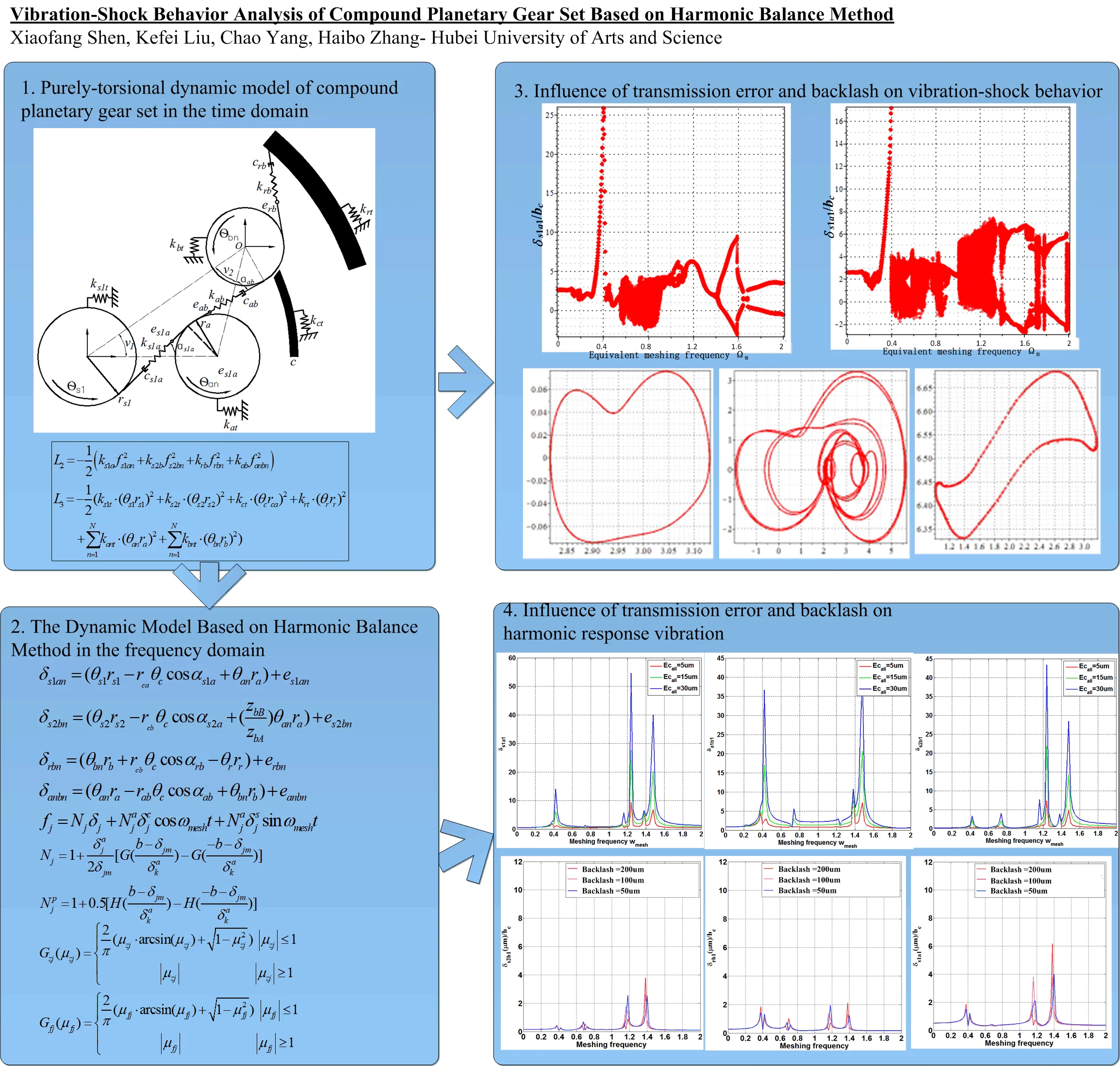
Due to the clearance between the mating gears, a dynamic load rises and causes tooth impact and vibration. In the compound planetary gear set, under the interaction of transmission error, meshing stiffness, support stiffness and backlash, the unilateral tooth impact could evolve into bilateral tooth impact, resulting in a worse dynamic behavior. This work reveals the influence of internal excitations and external excitations on vibration-shock behavior, and, for this purpose, a “purely torsional” lumped parameter dynamics model of compound planetary gear set is built and combined with a harmonic balance method. The steady dynamics response under the frequency domain and time domain is given by the numerical solving method, and the results indicated that the bilateral impact occurs due to the transmission error. To avoid the influence of transmission error on the impact at the resonance peak, the input speed of the compound planetary gear set should avoid the resonance range and harmonious response range. To improve the tooth surface contact by increasing the backlash, it is recommended to decrease the initial velocity to below = 0.8.
Highlights
- This paper reveals the influence of internal excitations and external excitations on vibration-shock behavior, and, for this purpose, a "purely torsional" lumped parameter dynamics model of compound planetary gear set is built and combined with a harmonic balance method.
- The results indicated that, to avoid the influence of transmission error on frequency response, the initial velocity of the compound planetary gear set should avoid the resonance range and harmonious response range.
- An increase in the transmission error causes the peak value of resonance increasing largely at the low frequency range. No matter it occurs in the low frequency section or in the high frequency section, negative vibration occurs, indicating at that bilateral impact occurs due to the transmission error introduction.
- When the backlash increases, complex quasi-periodic motions accompanied with a chaotic motion appear. Besides, when the backlash increases, the meshing frequency reduces from 0.8 to 0.4, and a larger vibration amplitude has a negative value, indicating at that the backlash increases causing more intense vibration shock.
- The backlash increase causes more intense vibration shock, and the period of chaotic motion is advanced. To improve the tooth surface contact by increasing the backlash, it is recommended to decrease the initial velocity to below ωmesh=0.8.
1. Introduction
1.1. Vibration-shock behavior in gear transmission
Various internal excitations contribute to a large backlash between the mating gears, such as assembly error [1], manufacture error [2], tooth surface wear [3], cracks [4, 5] and vibration [6]. Due to an excessive backlash, the unilateral impact and bilateral impact generally occurs when the driving gear starts to engage into meshing, easily inducing the tooth surface pitting and crack. The compound planetary gear set [7] is widely used in the automobile, ship and aircraft industry, because of its advantage in compact structure and larger transmission ratio compared with the traditional planetary gear set and the parallel axis gear set. However, due to too many degrees of freedom in the “translation-torsion” dynamic model [7, 8], large iterative base of the harmonic balance method occurs when solving the partial differential equations, resulting in unable convergence of the solution in the frequency domain.
Different from [1-8], in this work, to investigate the vibration-shock behavior in compound planetary gear set, the harmonic balance method is incorporated with a “purely-torsional” lumped-parametric dynamics model, to reduce the free dimension of the equations and the difficulty of numerical convergence and to calculate the state solution both in in the time domain as well as in the frequency domain.
1.2. Impact of transmission error and backlash on vibration-shock behavior
To investigate the contact force and impact force in the gear transmission, Lin [9] introduced a 3D static model by using the finite element software. Wang [10] also introduced a 3D dynamic model to simulate the dynamic behavior in the spiral bevel gear system. Although the 3D simulation gives intuitive results for the gear meshing and impact, Chen [11] made experiments on the relation between the transmission error and meshing impact, and verified the results in his numerical model. His results indicated that the high-frequency component of transmission error contributes most to the formation of meshing impact in the low-frequency section. To investigate the vibration behavior of the composite beam structure, Pankaj Charan Jena [12, 13] used an analytical method and the finite element method to obtain natural frequencies and mode shapes. Dong [14] focused on the influence of backlash on meshing impact in the gear transmission, changed the backlash parameters to improve the meshing impact from the single-side impact to double-side impact.
Different from reference above, in this work, to investigate the impact of transmission error and backlash on vibration-shock behavior in the time domain, the bifurcation diagram and Poincare section are incorporated with a “purely-torsional” lumped-parametric dynamics model, to calculate the displacement and velocity in the torsional direction accurately and show the vibration amplitude and the shock speed visually.
1.3. Analysis of frequency domain impact on vibration-shock behavior
To reveal the influence of internal excitations on dynamic behavior of gear transmission in the frequency domain, Ren [15] studied the influence of clearance amount on bifurcation and chaotic motion in a gear-to-bearing transmission system based on the harmonic balance method. Ju [16] considered transfer error, tooth-side clearance and meshing stiffness changes comprehensively, and established a pure torsional dynamics model of a compound planetary gear by using the harmonic balance method, and analyzed meshing shock changes under different clearance and stiffness amplitudes. Wu and Zhang [3, 17] investigated the vibration-shock behavior of compound planetary gear set by using the harmonic balance method and incremental harmonic balance method respectively. Chen [18-19] investigated the vibration and impact of mechanical structures by creating a condensation method and model reduction technique, and calculated a high-order frequency response by experimental test to reduce the impact due to the high-frequency percussion in the vertical track.
Different from reference above, in this work, to investigate the impact of transmission error and backlash on vibration-shock behavior in the frequency domain, the harmonic balance method is introduced to calculate the intrinsic property and shows the unilateral shock and bilateral shock accurately.
1.4. Objectives and scope
According to the literature above, although lots of work are done on revealing the source of vibration and shock, there is a lack of vibration and shock behavior in the compound behavior. In this paper, the authors investigate the vibration-shock behavior analysis of compound planetary gear set by establishing a numerical dynamic model with a single degree of freedom for the compound planetary gear based on the Lagrange equations of the second kind and the harmonic balance method, in order to reveal the influence of transmission error and backlash on the unilateral and bilateral impact on the space between the mating gears in the time and frequency domains respectively.
2. Dynamic models in time and frequency domains
2.1. “Purely torsional” lumped parameter dynamic model
To improve the solving efficiency of frequency response characteristics for the compound planetary gear set and avoid a series of problems such as non-convergence of numerical iteration due to the introduction of harmonic balance method, the authors built a pure torsional dynamics model of compound planetary gear. The relationship between each meshing pair is shown in Fig. 1. To reflect the influence of transmission error and backlash on vibration and shock, a purely torsional model is built based on the Lagrange equations of the second kind, which allows calculating the meshing force fluctuations in the time domain.
Fig. 1Purely-torsional dynamic model of compound planetary gear set
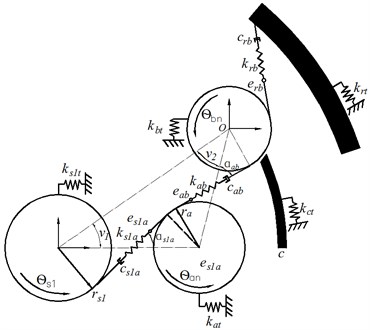
a) Input power route
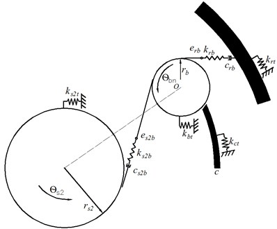
b) Output power route
Based on the Lagrange equation Eq. (4), pure torsional partial differential kinematics equations of compound planetary gear are derived, and the torsional displacements of gears, planetary frame and inner gear ring are set as generalized coordinates, as shown in Eqs. (1-3).
The total kinetic energy of the system components generated by the rotational motion:
The elastic potential energy of the system components system components generated by the meshing engagement:
The elastic potential energy of system members generated by the tangential torsional reaction force:
Eqs. (1-3) is the energy equation based on Lagrange principle, and Eq. (4) is the Lagrange equation of sun gear , , carrier , ring and planetary gear and respectively, where = 1, 2, 3. By introducing Eqs. (1-3) into Eq. (4) and taking a partial derivative under each generalized coordinate, the kinematic equation of each part is given at the torsional direction. The physical significance and assignment of other parameters involved in Eqs. (1-3) are shown in Table 1.
Table 1Parameters used in Eqs. (1-3)
Input parameters | Symbol and value |
Number of carriers | = 1 |
Number of sun gears | = 2 (, ) |
Number of rings | = 1 |
Module (mm) | = 4 |
Number of teeth | = 36, = 48, = 21, = 84 |
Position angle of planet gears | , , , , , |
Pressure angles | =20º |
Mean value of mesh stiffness (N/m) | =1×10⁹N/m, =1×10⁹N/m, =1×10⁹N/m, =1×10⁹N/m, = 1, 2, 3 |
Coefficient of stiffness fluctuation | = 0.3 |
Initial relative meshing phase | 0, 0, 0, 0, = 1, 2, 3 |
Torsional Reaction Stiffness (N/m) | = 1×10⁹, others = 0 |
Mass (kg) | = 5.812, = 12.309, = 5.038 = 5,698, = 1.997, = 3.139 |
Mass moment of inertia (kg/m2) | = 0.015, = 0.059, = 0.152, = 0.08, = 0.0019, = 0.0022 |
Base circle of gear (mm) | = 65.23, = 92.3, = 39.47, = 15.79 |
Gear Types | Spur |
Damping coefficient | = 0.06 |
Meshing frequency (Hz) | 1 |
Initial static transmission error (μm) | Sun gear has a 20 μm eccentricity error, others zero |
Initial backlash (μm) | Backlash between all meshing pairs is 100 μm |
Applied load (Nm) | = 2000 Nm, = 969.69 Nm |
2.2. Dynamic model based on harmonic balance method
Based on the “purely-torsional” dynamic model of compound planetary gear set with transmission error and backlash, the harmonic balance method is used to solve the frequency domain response, and the rigid body displacement included in the motion Eqs. (1-3) is eliminated by linear transformation. Taking the relative meshing displacement (= , , , ) as a new generalized coordinate. To improve the solving efficiency of differential equations, the time-varying meshing stiffness and backlash are transferred as a simple harmonic by the Fourier transform, including the fundamental wave and the first harmonic wave used in this paper. The relative meshing displacement expressed by the harmonic form is given below in the frequency domain and the time domain:
where in Eq. (5), is the steady state response of fundamental frequency, and are the first harmonic wave of the cosine amplitude and that of the sine amplitude respectively. Where in Eq. (6), is the relative meshing displacement at the rotational direction in the time domain. The time-varying meshing stiffness is given below in the frequency domain and the time domain:
where in Eq. (7), is the steady state response of fundamental frequency, and are the first harmonic wave of the cosine amplitude and that of the sine amplitude respectively. Where in Eq. (8), is the coefficient of stiffness fluctuation and is the initial relative meshing phase. The penetration depth is given below:
where in Eq. (9), is the piecewise function of penetration depth, is the average value of actual penetration depth, and are calculated as below:
where in Eq. (10), is the initial backlash in the meshing pair (= , , , ):
The actual penetration depth can be calculated by substituting Eqs. (11-13) to Eq. (10). The meshing force is calculated by multiplying the penetration depth by the time-varying meshing stiffness . The differential equations of motion in the harmonic form are given by introducing Eqs. (5-13) into Eqs. (1-4).
3. Analysis of vibration and shock behavior in time and frequency domains
3.1. Frequency domain analysis
To reveal the influence of transmission error and backlash on the shock and vibration behavior in the compound planetary gear set, the frequency domain response is solved by the numerical method, and the influence of transmission error and backlash on “vibration-shock” behavior is revealed for the compound planetary gear set based on the harmonic balance method.
3.1.1. Influence of transmission error on frequency response characteristics
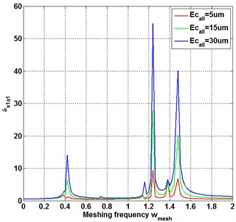
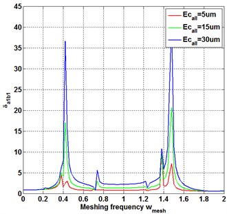
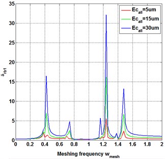
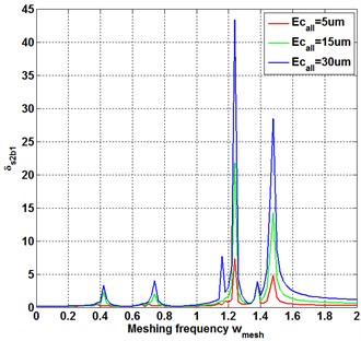
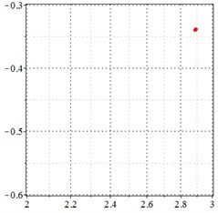
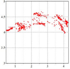
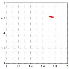
To reveal the influence of first harmonic sinusoidal component of transmission error on the frequency response, the backlash of all the meshing pairs is set as = 0 μm. With the first harmonic sinusoidal component of transmission error being increased from 5 μm to 30 μm, as shown in Fig. 2(a), the vibration amplitude near the resonance region increases obviously. Besides, one small vibration peak appears in the resonance region at the second natural frequency and the third natural frequency, indicating that the harmonic response vibration appears with the transmission error increasing to 30 μm. However, with the transmission error increase, the vibration amplitude at the frequency away from natural frequency and harmonic response frequency remain unchanged. The same phenomenon appears in other meshing pairs as shown in Fig. 2(b-d). With the transmission error increase, the vibration amplitude of inherent frequency increases obviously, and the harmonic response peak appears in the non-natural frequency band.
Fig. 2Influence of first harmonic sinusoidal component of transmission error on frequency response of each meshing pair under backlash = 0 μm (relative meshing displacement δj (j = s1an, s2bn, anbn, rbn))
a)
b)
c)
d)
This reveals that the transmission error increase intensifies the resonance and causes the harmonic response peak in the non-natural frequency band. To avoid the influence of transmission error on frequency response, the initial speed of the compound planetary gear set should avoid the resonance range and harmonious response range.
3.1.2. Backlash influence on frequency response characteristics
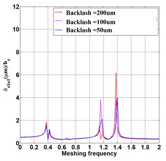
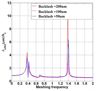
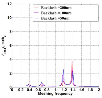
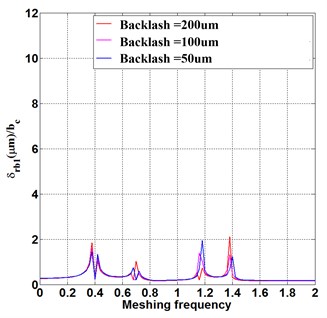
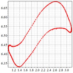
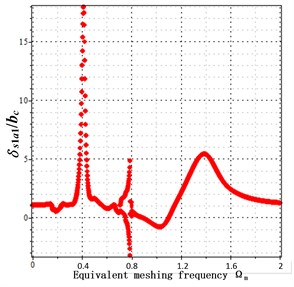
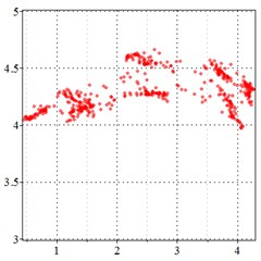
To reveal the influence of backlash on the frequency response, the fundamental wave component of transmission error is = 60 μm. With the backlash of all the meshing pairs increasing from 50 μm to 200 μm, in Fig. 3(a), the theoretic relative meshing displacement barely changes at the first and second order natural frequency of = 0.4 and 1.2, but increases largely at = 1.4. This indicates at that the backlash of in case of the increase of all the meshing pairs will induce a more intense resonance peak at the higher order natural frequencies, backlash increase results in a higher resonance peak in the condition of high running speed. Fig. 3 (b-d) demonstrates the same phenomenon as well, the backlash increase intensifies the resonance of high-speed motion. In Fig. 3(d), the increased backlash causes the resonance peak of relative meshing displacement larger equally at each inherent frequency. That is because the impact energy transmitted through multiple meshing pairs in the compound planetary gear is weakened due to the energy consumption.
Fig. 3Frequency response under fundamental wave component of transmission error Eim= 60 μm
a)
b)
c)
d)
3.2. Time domain analysis
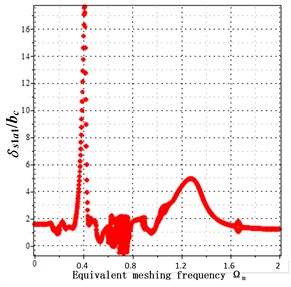
The steady-state response of the purely-torsional dynamic model in the frequency domain is calculated by the numerical method. To verify the influence of transmission error and backlash on the shock and vibration behavior in the frequency domain, a bifurcation diagram is created to search for the meshing frequency values which induce the single-side impact or double-side impact under different transmission errors and backlashes.
3.2.1. Transmission error
To show the inherent characteristic and the periodic motion visually (Fig. 4(a-c)), with the equivalent meshing frequency increasing from zero to 2, one hundred samples of continuous vibration period is distributed at each meshing frequency. At the equivalent meshing frequency = 0.4 in Fig. 4(a-c), the resonance peak appears and indicates of the first order natural frequency. The same is depicted in the Fig. 2(a-d), which verifies the correctness of the theoretical results from this work. Although the resonance peak appears anyway, different vibration amplitudes occur when different transmission errors are introduced and considered.
Fig. 4a) bifurcation diagrams when backlash = 200 μm and transmission error = 0 μm, b) bifurcation diagrams when backlash = 200 μm and transmission error = 20 μm, c) bifurcation diagrams when backlash = 200 μm and transmission error = 30 μm. x-coordinate is non-dimensional meshing frequency, y-coordinate is the non-dimensional tooth deflection for meshing pair Ps1a1
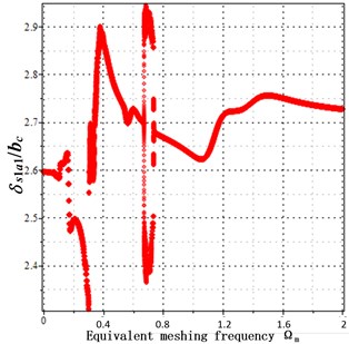
a) Non-transmission error
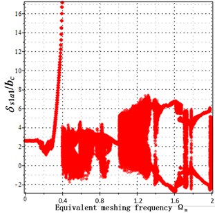
b) Transmission error = 20 μm
c) transmission error = 30 μm
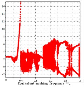
From Fig. 4(a-c) it is clearly seen that when a transmission error increases, the dimensionless vibration amplitude of meshing pair increases largely from 2.9 to 26. This indicates that the transmission error increase causes the peak value of resonance to increase largely at the low frequency range. However, at the high meshing frequency = [1.2-2], the transmission error increase makes little effect on the vibration amplitude. No matter in the low frequency section and in the high frequency section, negative vibration occurs, indicating at that bilateral impact occurs due to the introduction of the transmission error.
Besides, with the transmission error increasing from Fig. 4(a-c), random vibrations mainly located in the mid-frequency section and the high-frequency section. This indicates that the transmission error increase causes irregular vibration and makes harmful effect on the periodic vibration. Due the limitations of bifurcation graphs, the phase trajectory and the Poincare interface are introduced in this paper.
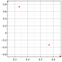
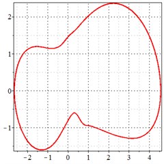
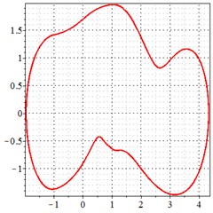
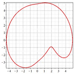
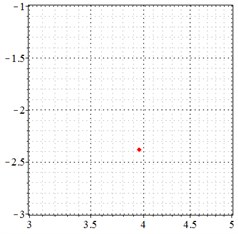
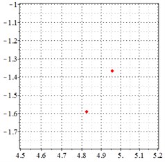
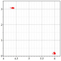
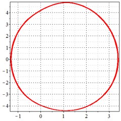
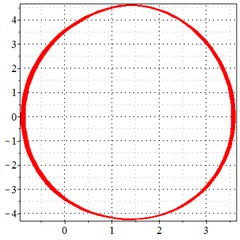
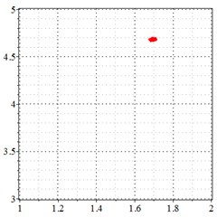
Fig. 5At meshing frequency ωmesh = 0.5 when the backlash = 200 μm, a)-c) is the phase trajectory under different transmission errors, and d)-f) is the Poincare interface under different backlashes, x-coordinate is the non-dimensional theoretical penetration depth of meshing pair Ps1a1, y-coordinate is the non-dimensional theoretical penetration velocity of meshing pair Ps1a1
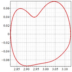
a) 0 μm transmission error

b) 20 μm transmission error
c) 30 μm transmission error
d) 0 μm transmission error
e) 20 μm transmission error
f) 30 μm transmission error
As seen in Fig. 5(a-c), at meshing frequency = 0.5, when the transmission error increases, one periodic motion turns into the doubled periodic motion, and the vibration amplitude also increases. Fig. 5(d-f) shows that when the transmission error increases, one single isolated point is changed to the doubled isolated point, and the theoretical penetration velocity also increases. Although the transmission error increase makes little effect on the periodic motion at the low-frequency meshing section, a larger transmission error causes a higher vibration velocity, by comprising the -coordinate from Fig. 5(d-f).
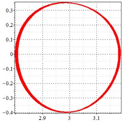
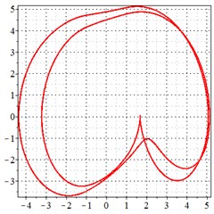
As seen in Fig. 6(a-c), at meshing frequency = 0.84, when the transmission error increases, one periodic motion turns into quasi periodic motion, and the vibration amplitude also increases. Fig. 6(d-f) shows that when the transmission error increases, one single isolated point is changed to a doubled isolated point, and the theoretical penetration velocity also increases. The same conclusion is made as from Fig. 5(a-c), by comprising the Fig. 6(d-f) with each other, the transmission error increase makes little effect on periodic motion at the medium-frequency meshing section, but causes the vibration amplitude rise by comprising Fig. 6(d-f) with each other.
Fig. 6At the meshing frequency ωmesh = 0.84 when the backlash = 200 μm, a)-c) is the phase trajectory under different transmission errors, and d)-f) is the Poincare interface under different backlashes, x-coordinate is the non-dimensional theoretical penetration depth of meshing pair Ps1a1, y-coordinate is the non-dimensional theoretical penetration velocity of meshing pair Ps1a1
a) 0 μm transmission error
b) 20 μm transmission error
c) 30 μm transmission error
d) 0 μm transmission error
e) 20 μm transmission error
f) 30 μm transmission error
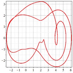
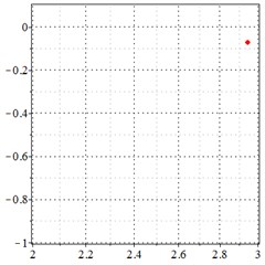
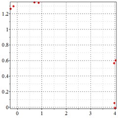
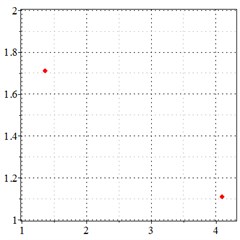
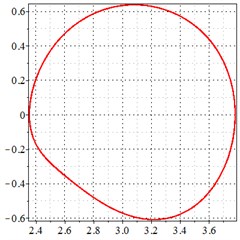
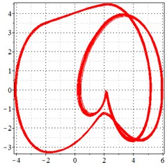
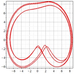
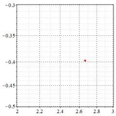
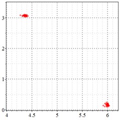
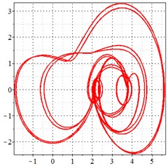
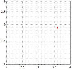
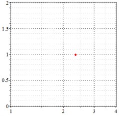
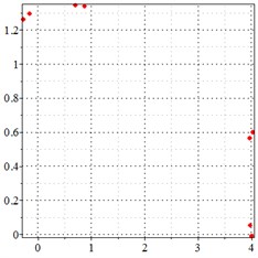
Fig. 7At meshing frequency ωmesh = 1.97 when the backlash = 200 μm, a)-c) is the phase trajectory under different transmission errors, and d)-e) is the Poincare interface under different backlashes, x-coordinate is the non-dimensional theoretical penetration depth of meshing pair Ps1a1, y-coordinate is the non-dimensional theoretical penetration velocity of meshing pair Ps1a1
a) 0 μm transmission error
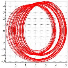
b) 20 μm transmission error
c) 30 μm transmission error
d) 0 μm transmission error
e) 20 μm transmission error
f) 30 μm transmission error
As seen in Fig. 7(a-c), at meshing frequency = 1.97, when the transmission error increases, one periodic motion turns into the doubled periodic motion and quasi-periodic motion. Fig. 7(d-f) shows that when the transmission error increases, one single isolated point is changed to a regular set of points, and the transmission error increase causes a higher vibration velocity as compared to the y-coordinate from Fig. 7(d-f).
By comparing with Figs. 4-7, it is indicated that the introduction of transmission error into the compound planetary gear set causing a worse periodic motion to turn from one periodic motion into the doubled periodic motion and quasi-periodic motion. The introduction of transmission error causes a negative vibration value, indicating at bilateral impact. Besides, the transmission error increase causes a higher vibration velocity, resulting in a larger shock and vibration at the high frequency meshing section.
3.2.2. Backlash
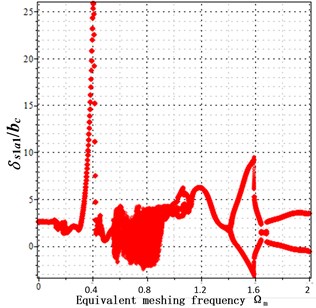
To reveal the influence of backlash on shock and vibration, different backlashes are introduced with the same transmission error in Fig. 8(a-c). When the backlash increases, complex quasi-periodic motions accompanied with a chaotic motion appear. Besides, when the backlash increases, the meshing frequency reduces from 0.8 to 0.4, and a larger vibration amplitude has a negative value, indicating at that the backlash increases causing more intense vibration shock, and the period of chaotic motion is advanced. To reveal the influence of backlash increase on periodic motion and vibration shock, the phase trajectory and Poincare interface are obtained under the condition of the different backlashes.
Fig. 8a) bifurcation diagrams with backlash = 50 μm and transmission error = 20 μ, b) bifurcation diagrams with backlash = 100 μm and transmission error = 20 μm, c) bifurcation diagrams with backlash = 200 μm and transmission error = 20 μm. x-coordinate is non-dimensional meshing frequency, y-coordinate is the non-dimensional tooth deflection for meshing pair Ps1a1
a) Backlash = 50 μm
b) Backlash = 100 μm
c) Backlash = 200 μm
Fig. 9At meshing frequency ωmesh = 0.5 when the transmission error = 20 μm, a)-c) is the phase trajectory under different backlashes, and d)-f) is the Poincare interface under different backlashes, x-coordinate is the non-dimensional theoretical penetration depth of meshing pair Ps1a1, y-coordinate is the non-dimensional theoretical penetration velocity of meshing pair Ps1a1
a) 50 μm backlash
b) 100 μm backlash
c) 200 μm backlash
d) 50 μm backlash
e) 100 μm backlash
f) 100 μm backlash
Fig. 10At meshing frequency ωmesh = 0.84 when the transmission error = 20 μm, a)-c) is the phase trajectory under different backlashes, and d)-f) is the Poincare interface under different backlashes, x-coordinate is the non-dimensional theoretical penetration depth of meshing pair Ps1a1, y-coordinate is the non-dimensional theoretical penetration velocity of meshing pair Ps1a1
a) 50 μm backlash
b) 100 μm backlash

c) 200 μm backlash
d) 50 μm backlash
e) 100 μm backlash
f) 100 μm backlash
As seen in Fig. 9(a-c), at meshing frequency = 0.5, when the backlash increases, one periodic motion turns into the doubled periodic motion, and the vibration amplitude remains unchanged. Fig. 9(d-f) shows that the when transmission error increases, one single isolated point is changed to the doubled isolated points, and the theoretical penetration velocity remains unchanged as well. It is indicated that, the backlash increase makes little effect on periodic motion and shock at the low-frequency meshing section. This is because that, at a low velocity, the shock kinetic energy is low as well due to a backlash between the teeth. Although the backlash increase causes the bilateral impact, the impact velocity is too low, as shown in the -coordinate of Fig. 9(d-f).
As seen in Fig. 10(a-c), at meshing frequency = 0.84, when the backlash increases, one periodic motion turns into the doubled periodic motion and quasi-periodic motion. Fig. 10(d-f) shows that when the backlash increases, one single isolated point is changed to two isolated points and to a set of points. The same conclusion is made as from Fig. 9(d-f), by comprising Fig. 10(d-f) with each other, the backlash increase makes little effect on the periodic motion at the medium-frequency meshing section due to the low kinetic energy of meshing impact.
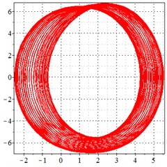
Fig. 11At meshing frequency ωmesh = 1.97 when the transmission error = 20 μm, a)-c) is the phase trajectory under different backlashes, and d)-f) is the Poincare interface under different backlashes, x-coordinate is the non-dimensional theoretical penetration depth of meshing pair Ps1a1, y-coordinate is the non-dimensional theoretical penetration velocity of meshing pair Ps1a1
a) 50 μm backlash
b) 100 μm backlash

c) 200 μm backlash
d) 50 μm backlash
e) 100 μm backlash
f) 100 μm backlash
As seen in Fig. 11(a-c), at meshing frequency = 1.97, when the backlash increases, one periodic motion turns into a quasi-periodic motion accompanied with chaotic motion. Fig. 11(d-f) shows that when the backlash increases, one single isolated point is changed to an irregular set of points.
By comprising with Figs. 8-11, it is indicated that when the backlash increases in the compound planetary gear set causing a causing a worse periodic motion to turn from one periodic motion into quasi-periodic motion and chaotic motion at the high meshing frequency section, and has little effects on the periodic motion at a low and medium meshing frequency due to the low kinetic energy of meshing impact. The backlash increase causes more intense vibration shock, and the period of chaotic motion is advanced. To improve the tooth surface contact by increasing the backlash, it is recommended to decrease the initial velocity to below = 0.8.
4. 4. Conclusions
To reveal the influence of the transmission error and backlash on the shock and vibration behavior in the compound planetary gear set, the authors establish a “purely-torsional” lumped parameter dynamic model of compound planetary gear set and use the harmonic balance method to calculate the steady dynamic response in the time and frequency domains. The results are as follows:
1) A transmission error increase intensifies the resonance and causes the harmonic response peak at the non-natural frequency. To avoid the influence of transmission error on frequency response, the initial velocity of the compound planetary gear set should avoid the resonance range and harmonious response range.
2) The backlash increase of all the meshing pairs will lead to a more intense resonance peak at higher order natural frequencies, backlash increase results in a larger resonance peak under a high running speed.
3) An increase in the transmission error causes the peak value of resonance increasing largely at the low frequency range. No matter it occurs in the low frequency section or in the high frequency section, negative vibration occurs, indicating at that bilateral impact occurs due to the transmission error introduction.
4) At the low-frequency meshing section, although the transmission error increase makes little effect on the periodic motion, a larger transmission error causes a higher vibration velocity. At the medium-frequency meshing section, the transmission error increase makes little effect on the periodic motion, but causes the vibration amplitude rise. At the high frequency meshing section, the introduction of transmission error causes a negative vibration value, indicating at that a bilateral impact occurs, and the transmission error increase causes a higher vibration velocity, resulting in a larger shock and vibration.
5) When the backlash increases, complex quasi-periodic motions accompanied with a chaotic motion appear. Besides, when the backlash increases, the meshing frequency reduces from 0.8 to 0.4, and a larger vibration amplitude has a negative value, indicating at that the backlash increases causing more intense vibration shock.
6) At the low-frequency meshing section, the backlash increase makes little effect on periodic motion and shock. At the medium-frequency meshing section, the backlash increase makes little effect on the periodic motion due to the low kinetic energy of meshing impact. At the high-frequency meshing section, the backlash increases in the compound planetary gear set causing a worse periodic motion to turn from one periodic motion into quasi-periodic motion and chaotic motion.
The backlash increase causes more intense vibration shock, and the period of chaotic motion is advanced. To improve the tooth surface contact by increasing the backlash, it is recommended to decrease the initial velocity to below = 0.8.
References
-
S. Li, “Finite element analyses for contact strength and bending strength of a pair of spur gears with machining errors, assembly errors and tooth modifications,” Mechanism and Machine Theory, Vol. 42, No. 1, pp. 88–114, Jan. 2007, https://doi.org/10.1016/j.mechmachtheory.2006.01.009
-
Y.-P. Shih and Y.-J. Li, “A novel method for producing a conical skiving tool with error-free flank faces for internal gear manufacture,” Journal of Mechanical Design, Vol. 140, No. 4, p. 04330, Apr. 2018, https://doi.org/10.1115/1.4038567
-
H. Zhang and C. Yang, “Modelling of time-varying meshing stiffness under tooth wear condition for nonlinear dynamics in compound planetary gear set,” Journal of Vibroengineering, Vol. 23, No. 8, pp. 1800–1819, Dec. 2021, https://doi.org/10.21595/jve.2021.21964
-
B. Shu and W. G. Liu, “Impacts of multiple tooth root cracks on time-varying mesh stiffness of gear drive,” (in Chinese), Science Technology and Engineering Journal, Vol. 51, No. 3, pp. 29–36, 2018.
-
P. C. Jena, D. R. Parhi, and G. Pohit, “Dynamic study of composite cracked beam by changing the angle of bidirectional fibres,” Iranian Journal of Science and Technology, Transactions A: Science, Vol. 40, No. 1, pp. 27–37, Mar. 2016, https://doi.org/10.1007/s40995-016-0006-y
-
L. Son, M. Bur, and M. Rusli, “A new concept for UAV landing gear shock vibration control using pre-straining spring momentum exchange impact damper,” Journal of Vibration and Control, Vol. 24, No. 8, pp. 1455–1468, Apr. 2018, https://doi.org/10.1177/1077546316661470
-
H. Zhang and X. Shen, “A dynamic tooth wear prediction model for reflecting “two-sides” coupling relation between tooth wear accumulation and load sharing behavior in compound planetary gear set,” Proceedings of the Institution of Mechanical Engineers, Part C: Journal of Mechanical Engineering Science, Vol. 234, No. 9, pp. 1746–1763, May 2020, https://doi.org/10.1177/0954406219900085
-
S. J. Wu et al., “Impact of mesh errors on dynamic load sharing characteristics of compound planetary gear sets,” (in Chinese), Journal of Mechanical Engineering, Vol. 51, No. 3, pp. 104–110, 2015.
-
T. Lin, H. Ou, and R. Li, “A finite element method for 3D static and dynamic contact/impact analysis of gear drives,” Computer Methods in Applied Mechanics and Engineering, Vol. 196, No. 9-12, pp. 1716–1728, Feb. 2007, https://doi.org/10.1016/j.cma.2006.09.014
-
P.-Y. Wang, S.-C. Fan, and Z.-G. Huang, “Spiral bevel gear dynamic contact and tooth impact analysis,” Journal of Mechanical Design, Vol. 133, No. 8, p. 08450, Aug. 2011, https://doi.org/10.1115/1.4004544
-
Y. Chen, A. S. Escalera Mendoza, and D. T. Griffith, “Experimental and numerical study of high-order complex curvature mode shape and mode coupling on a three-bladed wind turbine assembly,” Mechanical Systems and Signal Processing, Vol. 160, No. 3, p. 107873, Nov. 2021, https://doi.org/10.1016/j.ymssp.2021.107873
-
P. C. Jena, “Free vibration analysis of short bamboo fiber based polymer composite beam structure,” Materials Today: Proceedings, Vol. 5, No. 2, pp. 5870–5875, 2018, https://doi.org/10.1016/j.matpr.2017.12.185
-
P. Jena, D. Parhi, and G. Pohit, “Theoretical, numerical (FEM) and experimental analysis of composite cracked beams of different boundary conditions using vibration mode shape curvatures,” International Journal of Engineering and Technology, Vol. 6, No. 2, pp. 509–518, 2014.
-
H. Dong, Z. Fang, and X. Zhao, “Nonlinear characteristics of herringbone gear four-branching transmission considering gear backlash effect,” Journal of Mechanical Strength, Vol. 39, No. 5, pp. 1112–1118, 2017, https://doi.org/10.16579/j.issn.1001.9669.2017.05.020
-
H.-P. Ren, Z.-X. Zhou, and C. Grebogi, “Nonlinear dynamics in the flexible shaft rotating–lifting system of silicon crystal puller using Czochralski method,” Nonlinear Dynamics, Vol. 102, No. 2, pp. 771–784, Oct. 2020, https://doi.org/10.1007/s11071-020-05592-9
-
R. Ju, W. Fan, and W. D. Zhu, “An efficient Galerkin averaging-incremental harmonic balance method for nonlinear dynamic analysis of rigid multibody systems governed by differential-algebraic equations,” Nonlinear Dynamics, Vol. 105, No. 1, pp. 475–498, Jul. 2021, https://doi.org/10.1007/s11071-021-06367-6
-
Z. H. Liu and S. J. Wu, “Nonlinear dynamics of compound planetary gear sets based on incremental harmonic balance method,” (in Chinese), Journal of Vibration and Shock, Vol. 31, No. 3, pp. 117–122, 2012.
-
Y. Chen, B. Zhang, N. Zhang, and M. Zheng, “A condensation method for the dynamic analysis of vertical vehicle-track interaction considering vehicle flexibility,” Journal of Vibration and Acoustics, Vol. 137, No. 4, p. 04101, Aug. 2015, https://doi.org/10.1115/1.4029947
-
Y. Chen, B. Zhang, and S. Chen, “Model reduction technique tailored to the dynamic analysis of a beam structure under a moving load,” Shock and Vibration, Vol. 2014, pp. 1–13, 2014, https://doi.org/10.1155/2014/406093
About this article

The authors would like to thank the “High-Speed Gear Shaft Drive System Xiangyang Key Laboratory” for the financial and technological support of this study throughout the project “non-contact labyrinth seal optimization for 16000 rpm high-speed gearbox” and “Research on Vibration Noise Reduction Technology of High Speed Gearbox”.
The authors would like to thank the Xiangyang Science and Technology Research and Development Program of China for the financial and technological support of this study throughout the project “High Speed Gear Box Lubrication and Lightweight Technology” (2020ABH001912), the project “Inhibitory Effect and Molecular Mechanism of Kirenol on Orthotopic Lung Cancer in Lewis Mice” (2021YL48).
The authors would like to thank the Hubei Superior and Distinctive Discipline Group of “Mechatronics and Automobiles” (XKQ2021043) for the financial and technological support of this study throughout the project “Research on Vibration and Noise Reduction Mechanism of High-Speed Gear”.
The datasets generated during and/or analyzed during the current study are available from the corresponding author on reasonable request.
The authors declare that they have no conflict of interest.
