Abstract
Due to a large number of components, complex meshing relations and high requirements for assembly accuracy, the dynamic characteristic of compound planetary gear, such as vibration, impact, periodic motion and load sharing, are more easily affected by internal excitation than those of simple planetary gear set and parallel shafting gear set. To improve the load sharing behavior and the resistance of Chaos motions in the compound planetary gear set, in this work, by introducing the floating support into the center gear and planet gear, a lumped-parameter dynamic model of the compound planetary gear set is built based on the lumped parameter method and Lagrange kinematics equation. The steady response is calculated by numeric method to investigate the influence of floating support from different components on loading sharing behavior and periodic motion. The results indicate that, the increase of the floating value of all components improves the instantaneous load-sharing behavior, and single floating of planet gear reduces the load sharing behavior. To avoid the system being in quasi-periodic motion and Chaos motions under the condition of floating support, the input speed should be avoided away from the range of 3201 r/min-5069 r/min.
Highlights
- In this work,based on the second Lagrange equation, a translation-torsional dynamic model of compound planetary gear set including floating support is proposed and calculated in time-domain by numerical method.
- Single floating of planet gear reduces the load sharing behavior of compound planetary gear set. To improve the load sharing behavior efficiently, each planet gears should be equally applied on floating value.
- Under the condition of all components floating together, the increase of the floating value of all components improves the instantaneous load-sharing behavior of the compound planetary gear.
- If it is necessary to add floating support to improve the load-sharing behavior in a compound planetary gear set, it is suggested to maintain the meshing frequency in the input speed range of 0~1067r/min.
- In order to reduce the vibration velocity and amplitude at the input speed range of 1067 r/min ~2401r/min, it is suggested to add a floating support to each component.
- In order to avoid the system being in quasi-periodic motion and Chaos motions under the condition of floating support, the input speed of sun gear s1 should be avoided the range of 3201r/min~5069r/min.
1. Introduction
Due to the characteristics of its structure, the compound planetary gear has a large number of supporting shafting, and a single supporting shaft often bears the supporting load from multiple gears. When vibration, shock or impinges occurs on the supporting load, due to transmission error or clearance from mating gears and bearings, dynamic load [1] of supporting load will be transferred to the shafting through the contact of the axle and hole, causing the vibration of the shafting and even further decreasing the dynamic characteristics of the gear train. To resist the influence of transmission error and meshing impact caused by backlash on shafting components, floating support is generally used in the center construction of epicyclic gear train, such as carriers, sun gears and rings, to buffer the contact collision caused by axle-hole clearance.
In the development of the stationary technology for the gear transmission system [2], many solutions have appeared by adding floating support and changing the floating mechanism: Kahraman [3] investigated the influence of time-varying meshing stiffness on the support clearance for the parallel-shaft gear system, and found that the dynamic load caused by meshing stiffness fluctuation further amplified the shafting vibration through the support clearance. Considering gravity, bearing clearance and input torque, a torsional dynamic model of planetary gear gearbox is given by Guo et al. [4], to investigate the influence of internal and external excitation on the load-sharing performance in a simple planetary gear set. By introducing floating support into the central component of the epicycle gear train and numerical simulation, Wu [5] found that the floating support of the central component reduced the vibration amplitude. To further verify the influence of floating support on the average load characteristics of the epicyclic gear train, a two-dimensional “pure-torsion” dynamic model of planetary gear is built by Tsai [6] to calculate the average load coefficient under different floating values. Taking the impact of load on floating support into account, Xu [7] concentrated on the load sharing behavior of the planetary gear set under heavy load and floating support. The results show that, the central component floating together improves load sharing behavior obviously, compared with the single floating of the central component. Wang [8] proposed a floating mechanism with an adjustable floating volume, which realized the floating volume adjustment for center gears by adjusting the gear clearance. Zeng et al. [9-11] investigated the vibration sources of a gear-box by experimental investigation.
In addition to the influence of floating support on the load sharing behavior, scholars have also carried out studies on other dynamic characteristics of the gear train under floating support. By using Poincare interface and phase orbit analysis methods, Guo [12] established a dynamic model of planetary gear with eccentric errors, component floating and transmission errors, and found that the existence of floating clearance was not conducive to maintaining the stability of the rotation components [13-14]. Through 3D modeling and modal analysis, Nejad [15] investigated the floating combination for the wind turbine’s planetary gearbox. Wang [16] established a mathematical model on the gear-rotor-bearing system and found that the manufacturing error of floating support and the installation error of planetary gear mainly decreased the transmission stability of gear multi-support of rotors. Cai [17] investigated the influence of planetary gear numbers on the floating support. Wang [18] carried out fault diagnosis research on the planetary gear box containing ring floating, and obtained the system spectrum under floating support. Chung [19] investigates the floating effects on the load sharing behavior of planetary gear set. Yi [20] built a coupled dynamic model to reflect the load sharing behavior in the helical gears-shafts-bearings system, and verified that decreasing transmission error could improve load sharing behavior. Chen et al. [10, 21, 22] introduced spring damping pair to describe the meshing force between mating gears and investigated the dynamics under the time-varying fluctuation of meshing stiffness.
According to the literature listed above, although most of the current researches on floating support of gear transmission system focus on the relationship between floating and load sharing behavior for the simple planetary gear system, no research has been processed on floating support in the compound planetary gear system. In this work, and a “translation-torsion” lumped parameter dynamic model of the compound planetary gear set is established, to reveal the influence of floating support on vibration impact, periodic motion and load sharing behavior of the compound planetary gear under the condition of transmission error, backlash and time-varying meshing stiffness.
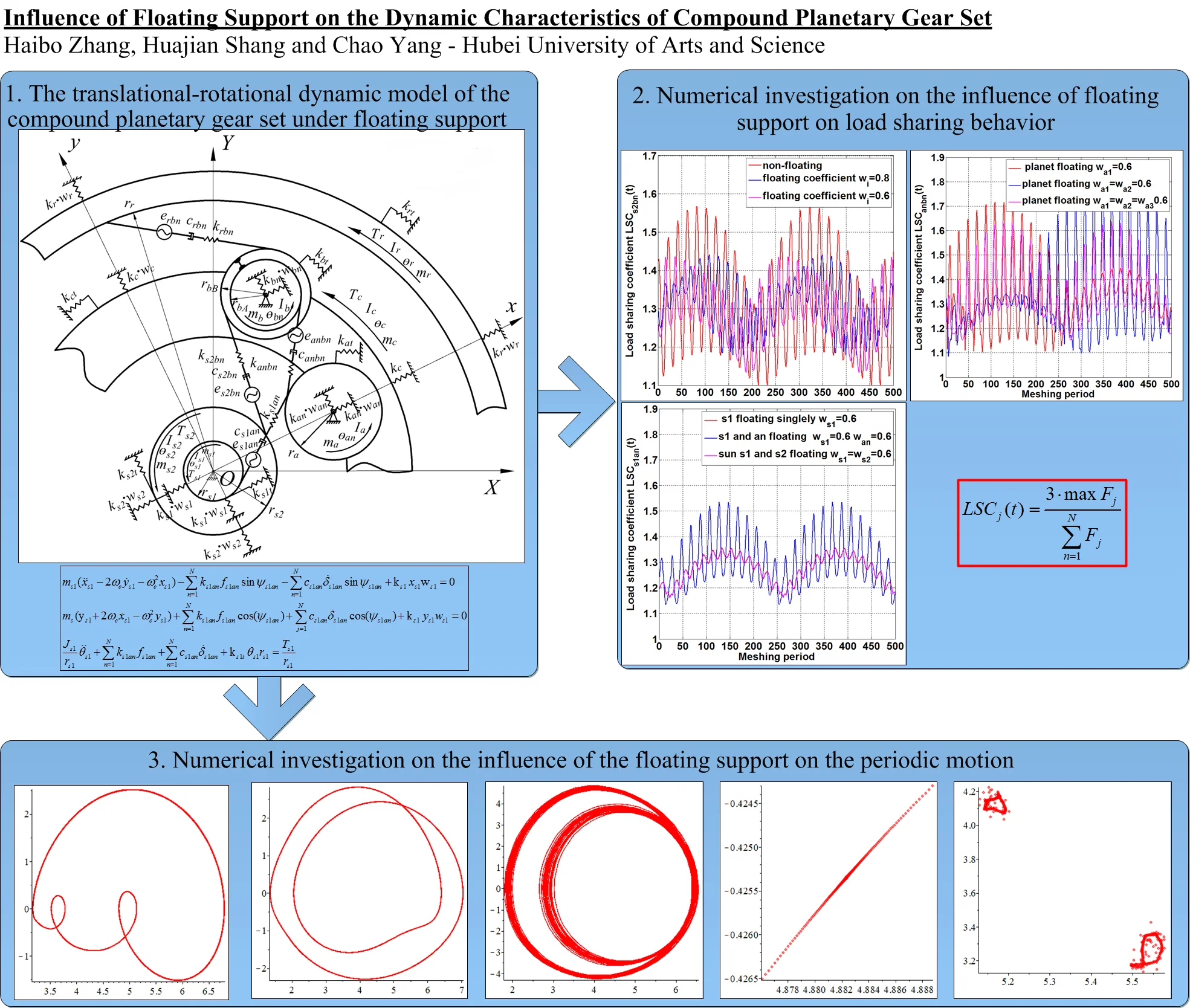
2. Modeling of the compound planetary gear set under floating support
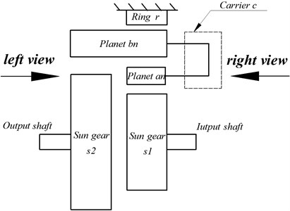
To investigate the relationship between the floating supports from different components and the dynamic characteristics of the compound planetary gear, a “translational-torsional” lumped parameter dynamics model proposed and established by Zhang [23] is introduced in this work, and the structure of compound planetary gear set of Ravenna type is consistent with [23-25], as shown below in Fig. 1.
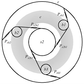
As shown in Fig. 1(a), there are two types of components in the Ravigneaux compound planetary gear set: the central component (Sun gear and , carrier and ring gear ), and the planet gears ( and ). The planet gears not only rotate freely around its axis, but also revolve around the center of the gear system under the support of carrier . Among them, planet gears mesh with sun gear , and also meshes with the long planet wheel , which forming a planet gear meshing pair between planet gear and . In general, represents the serial number of planet gears, and in this paper, 1, 2, 3. The central gear engages with three planetary gears, which arranges symmetrically in space, as shown in Fig. 1(b), where represents the first pair of sun gear – planet gear meshing pair, and (1, 2, 3) represent the planet-palnet meshing pair and the ring meshing pair respectively.
Fig. 1Diagram of Ravigneaux compound planetary gear set
a) Main view of Ravigneaux compound gear set
b) Left view of Fig. 1(a)
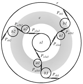
c) Right view of Fig. 1(a)
Fig. 2The translational-rotational dynamic model of the compound planetary gear set under floating support
Periodic time-varying meshing stiffness of meshing pairs , , and ( 1, 2, 3) are expressed by , , and respectively, whose meshing force is determined by the piecewise linear profile gap function (, , , ) [15], [17]:
where in Eq. (1), is the theoretical meshing displacement from penetration depth of mating gears, and its amplitude reflects the deformation of the meshing pair without considering the backlash between mating surface, as shown in Eq. (2). is the backlash on meshing pair . When the theoretical meshing displacement is greater than the backlash , - is the actual meshing displacement for calculating meshing force in meshing pair . The dynamic meshing force is given by multiplying by the actual meshing displacement and time-varying meshing stiffness in Eqs. (3,4), which are cited in [16]:
To investigate the influence of floating support on dynamics of compound planetary gear set, floating coefficients is introduced into each supporting of components, and is incorporated with support stiffness for center gears and planet gears, as shown below:
where in Eqs. (5, 6), and is the translational displacement on -direction and -direction for the component , and is observed under rotational coordinate system . is the support stiffness of the axle-hole joint on component under the condition without floating. is the floating coefficients. By incorporating the floating coefficients and the support stiffness, kinetic equations of the central component and the planet gears are derived based on Lagrange’s Equation of Motion:
Central gear :
Planet gear an (1, 2, 3):
Planet gear (1, 2, 3):
Central gear :
Planet carrier :
Ring :
where in Eqs. (7-12), 10 components and 30 kinematic equations form together for the dynamic model of the compound planetary gear set, and the description of each parameter is shown in shown in Appendix Tables A1-A2.
3. Influence of floating support on load sharing behavior
To quantify the influence of floating value on load sharing behavior from different meshing pairs of compound planetary gear, the floating coefficient is introduced into the support of central gear and the planet gear respectively, to change the support stiffness.
To study the load distribution in each meshing pair, dynamic load coefficient (, , , ) is introduced. Definitions for three different types of load sharing coefficients are given [25] below:
where is the meshing force defined in Eq. (4). The load sharing definition is applied in all the other meshing pairs. The parameters values of numerical simulation are shown in Appendix Table A3. Under the condition that the floating coefficients of all components are consistent and change synchronously, the calculation results are shown in Fig. 3.
Fig. 3The influence of floating support on load-sharing behavior of different meshing pairs under the condition of the same floating coefficient
a) Meshing pair
b) Meshing pair
c) Meshing pair
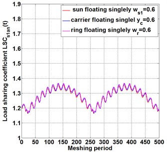
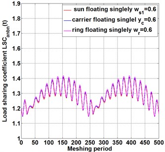
When the floating coefficient of all components is 1, which represents non-floating support, as shown in the red line in Fig. 3(a-c).With the floating coefficient at each support increasing from 0.8 to 0.6, the floating value increases also, compared with the load sharing coefficient curve under non-floating, increasing the floating coefficient of each component decrease the amplitude of the load sharing fluctuation in meshing pair , as shown in blue line and purple line of Fig. 3(a), and the fluctuation style of load sharing coefficient remain unchanged. It is indicated that increasing floating value improves the instantaneous load sharing behavior for meshing pair . Similarly, in meshing pair , as shown in Fig. 3(b), and in meshing pair , as shown in Fig. 3(c),floating increasing decreases the instantaneous load sharing coefficient and . The difference is that, Compared with meshing pairs , the load sharing behavior of meshing pairs and meshing pairs is more obviously affected with floating change, and the increase of floating quantity improves the load distribution performance of meshing pairs and significantly. The reason for this difference is that, an initial transmission applied on sun gear causes unbalance loading distribution on planet gears , and . In the process of power transmission from power input gear to meshing pair ,and meshing pairs , the internal excitations in gears system, such as backlash, transmission error, meshing stiffness and so on, enlarge the unbalance loading distribution, resulting in a larger load sharing coefficient at power output end than that at input end . The floating support of sun gear at the power input end not only reduces the instantaneous load sharing coefficient , but also transmits the improved load performance to the output end. Therefore, at the power transmission line, the load sharing behavior improves more obviously with the floating coefficient increasing, resulting from the floating coefficient of each component increasing synchronous.
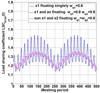
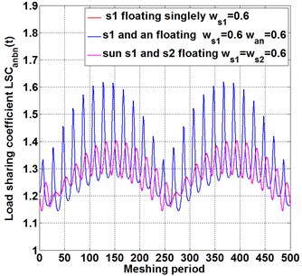
Fig. 4The influence of floating support on load-sharing behavior of different meshing pairs under different floating members
a)
b)
c)
d)
Fig. 5The influence of floating support numbers of gears on load-sharing behavior of different meshing pairs
a)
b)
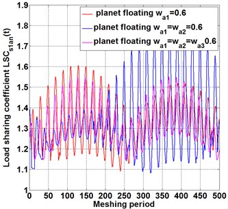
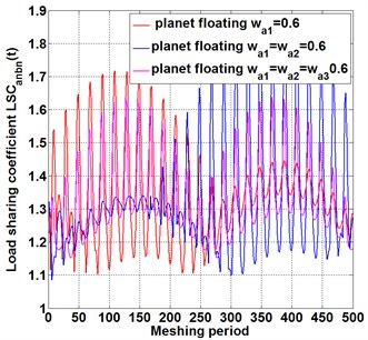
In Fig. 4(a), when the floating support is applied single on sun gear, carrier or ring, the time history curves of instantaneous load coefficient are similar between each other, which indicates that the effect of single floating of different center components on the load-sharing characteristics is similar. In Fig. 4(b), when the floating coefficient of each planet gear is identical (purple wire), instantaneous load coefficient is lower, compared with the condition that floating of only one planet (red wire) or two planets (blue wire). The same phenomenon also appears in the curve of instantaneous load coefficient for meshing pair , as shown in Fig. 4(c-d). Because that the load sharing behavior is largely determined by the uniformity of the load from the sun gear to the planet, The load fluctuation caused by the floating of the central component is evenly distributed to the planet gears, resulting in a harmonic uniformity around the central component. Similarly, when the floating coefficient is equally applied on each planet gear, as shown in the purple wire of Fig. 4(b-d), the fluctuations in dynamic load caused by the floating cancel out. However, only floating one or two planet gears cause the imbalance of dynamic load distribution among the three planet gears, resulting in unbalance load distribution and bad load sharing behavior, as shown in the red and blue wires of Fig. 4(b-d). The analysis above shows that, single floating of planet gear reduce the load sharing behavior of compound planetary gear set, and single floating of different central components has similar effects on load-sharing. To improve the load sharing behavior efficiently, each planet gears should be equally applied on floating value.
To seek methods to improve the load-sharing characteristics of the compound planetary gear set and find out the optimal configuration of floating support, as shown in Fig. 5(a). By comparing the floating of a single sun gear with that of two sun gears together, it is found that, the floating of two sun gears together reduce the load sharing coefficient largely, and the effect is better than that of a single floating on sun gear. While the floating planet gears (blue line) increases load sharing coefficient significantly, indicating that increasing the floating number of central components improve the load sharing behavior, while the floating of planet gears reduce load sharing behavior. The same phenomenon also occurs in meshing pair , as shown in Fig. 5(b), which verifies the correctness of the conclusion from Fig. 5(a).
4. The influence of the floating support on the periodic motion
The mode of vibration optimization is partially determined by the periodic motion. Generally, the vibration on mating gears can be optimized using directional error compensation under single and double periodic motion, while the vibration is not able to be eliminated under quasi-periodic and chaotic motion due to the uncertainty of motion. To find out the method of optimizing the periodic motion of the compound planetary gear, different floating quantities is applied on the different components, and the gear train periodic operation behaviors under different meshing frequencies and floating quantities are investigated by taking the meshing frequency and floating support as the excitation variables.
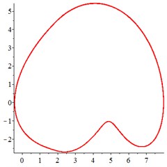
At the low-frequency section 0.4, in Fig. 6(a, d), the motion trajectory of relative meshing displacement of meshing pair presents a single closed curve, and the Poincare interface presents a single solitary point, which indicates that the vibration of the system moves in a single periodic motion. By introducing floating coefficient of all the components 0.8 into the system, in Fig. 6(b, e), although the motion trajectory still presents a single closed curve state and the Poincare interface presents a single isolated point, compared with Fig. 6(a, d), the vibration velocity of reduces greatly, indicating that the introduction of the floating support absorbs part of the vibration kinetic energy and reduces the vibration velocity at the gear tooth engagement. With the further increase of the floating value and decrease the floating coefficient 0.6, as shown in Fig. 6(c, f), the vibration of meshing pair maintain the single-period motion.
Fig. 6At meshing frequency ωmesh= 0.4, (a-c) is the phase trajectory under different floating coefficient, and (d-f) is Poincare interface under different floating coefficient, x-coordinate is the non-dimensional theoretical penetration depth of meshing pair Ps1a1, y-coordinate is non-dimensional theoretical penetration velocity of meshing pair Ps1a1. wall is the floating coefficient for all the components
a)1
b) 0.8
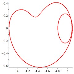
c)0.6
d)1
e)0.8
f)0.6
The above analysis shows that, the floating support reduces the vibration velocity at the gear tooth engagement, a larger floating amount or a lower floating coefficient, causes a smaller vibration velocity. Floating support does not change the single-period motion state in the low-frequency range. If it is necessary to add floating support to improve the load-sharing behavior in a compound planetary gear set, it is suggested to maintain the meshing frequency in the low-frequency range.
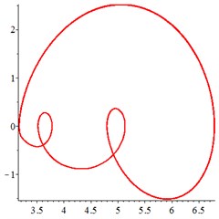
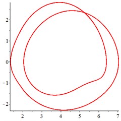
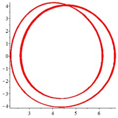
At the intermediate frequency section [0.4-0.9], and the input speed of sun gear improves. Under the condition of non-floating support, the vibration maintains a regular single-period motion state, as shown in Fig. 7(a, d). With the introduction of floating support in Fig. 7(b, e), the motion trajectory of meshing displacement changes from a single curve to a double closed curve, and the Poincare section is programmed from a single solitary point to two solitary points. Therefore, in this meshing frequency section, the vibration changes from a single periodic motion to a double periodic motion, as a result of floating support. With the floating value of all the components increasing further, as shown in Fig. 7(c, f), the motion trajectory of is no longer a closed curve with single cycle, but a closed curve with multiple cycles, indicating that the system enter into quasi-periodic motion.
In addition, by comparing the ordinate of Fig. 7(a-c) and Fig. 7(d-f), it is found that the increase of floating amount reduces the vibration velocity of the relative meshing displacement , indicating that the introduction of floating support can absorb vibration kinetic energy and reduce the meshing impact of gear teeth in the section of intermediate meshing frequency.
The above analysis shows that, in the section of intermediate meshing frequency, the introduction of floating support and the floating amount increasing results in the periodic motion change from single periodic motion to double periodic motion and even quasi-periodic motion. However, the vibration velocity and the meshing impact caused by the vibration of components are reduced by introducing floating support.
Fig. 7At meshing frequency ωmesh= 0.9, (a-c) is the phase trajectory under different floating coefficient, and (d-f) is Poincare interface under different floating coefficient, x-coordinate is the non-dimensional theoretical penetration depth of meshing pair Ps1a1, y-coordinate is non-dimensional theoretical penetration velocity of meshing pair Ps1a1. wall is the floating coefficient for all the components
a)1
b) 0.8
c)0.6
d)1
e)0.8
f)0.6
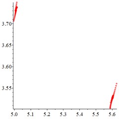
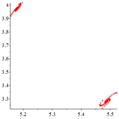
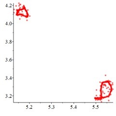
Fig. 8At meshing frequency ωmesh= 1.9, (a-c) is the phase trajectory under different floating coefficient, and (d-f) is Poincare interface under different floating coefficient, x-coordinate is the non-dimensional theoretical penetration depth of meshing pair Ps1a1, y-coordinate is non-dimensional theoretical penetration velocity of meshing pair Ps1a1. wall is the floating coefficient for all the components
a)1
b) 0.8
c)0.6
d)1
e)0.8
f)0.6
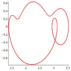
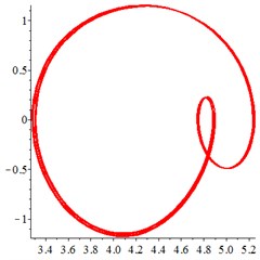
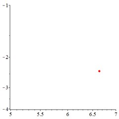
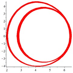
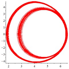
At the high-frequency section [1.2-1.9], vibration motion is not easy to maintain a single periodic motion, and most of them present quasi-periodic or even chaotic state, as shown in Fig. 8(a, d). The phase trajectory shows several closed curves, and the Poincare interface shows two isolated islands, indicating that the system is in quasi-periodic motion with good periodic motion. After the floating support is introduced, as shown in Fig. 8(b, e), the meshing displacement presents several closed curves. As the floating amount further increases, as shown in Fig. 8(c, f), the number of closed curves also increases, the number of isolated points in Poincare interface increases, and the distribution range becomes larger.
In addition, by comparing the ordinate of Fig. 8(a-c) and Fig. 8(d-f), it is found that, the floating amount increasing does not affect the vibration velocity of the relative meshing displacement , indicating that the introduction of floating support has little influence on the absorption of vibration kinetic energy in the high-frequency meshing section.
In the process of bifurcating through single periodic to chaos motion, bifurcation process goes through single periodic motion, double periodic motion, quasi-periodic motion and chaotic motion. Fall in between double periodic motion and chaotic motion, quasi-periodic bifurcation process is a typical way to chaos, and can be considered as a way to enter chaos from periodic window.
After a period of running time, if the vibration amplitude and velocity of the observation point changes regularly and periodically, such as single periodic motion and double periodic motion in Fig. 6, a corresponding periodic damping can be designed to counteract the regular vibrations. However, when quasi-periodic motion appears in Fig. 7(c) and Fig. 8(a), it’s going to be a longer period for the observation point to complete a cycle, compared to single periodic motion and double periodic motion. If chaos motion appears, periodic motion is replaced by random motion which is hard to controlled and eliminated.
The above analysis shows that, in the high-frequency meshing section [1.2-1.9], the introduction of floating support lead periodic motion to an unregulated state, and the increase of floating amount induce the quasi-periodic motion to chaotic motion, which is not conducive to the maintenance of regular periodic motion.
5. Literature validation
In this work, the validation of Eq. (7) to Eq. (12) comes from similar work in other’s literature, by using the Eq. (7) to Eq. (12) from Lagrange equations of the second kind, a lumped parameter “translational-rotational” model for compound planetary gear set (in Fig. 2) is built to calculate the vibration displacement and meshing force for each mesh pair. Similarly, Zhang [26] introduced the lumped parameter model and the equations of motion by using the Lagrange principle to calculate the meshing force and load sharing coefficient in two-stage planetary gear set, and the pure torsion equations of motion are given by Parker [27, 28] for compound planetary gear set.
Different from the equations of motion in Zhang [26] and Parker [27, 28], in this work, the “translational-rotational” equations of motion are derived for compound planetary gear set, with more degrees of freedom and more complex meshing relation. Based on Lagrange principle and modeling by lumped parameter method likewise, the equations 7 to 12 in this work could be verified by the similar work in Zhang [26] and Parker [27, 28].
The influence of transmission error and float on dynamic behavior was studied by Liu [29] and Du [30]. Different from this work, the load sharing coefficient is calculated by using the theory of equivalent mesh force. The results of Liu [29] indicated that, the floating of basic components of planetary gear can obviously reduce the load imbalance among planet gears, and the similar results of this work occurs in Fig. 3. Besides that, Du [30] found that, the load distribution uniformity is better when multiple components float together, and the similar conclusion of this work occurs in Fig. 4(b, d), where the load sharing coefficient under the condition of planet gears floating together is lower than the condition of floating individually.
In Fig. 6(a), at low meshing frequency section, the motion trajectory of relative meshing displacement of meshing pair presents a single closed curve, the similar results are verified by [29, 31] and indicates of a regular periodic vibration when input speed of gear is low.
From the Fig. 7(a-c), with the floating value increasing, the clearance between the mating gears increases as well, resulting in the periodic motion change from single periodic (Fig. 7(a)) motion to double periodic motion (Fig. 7(b)) and even quasi-periodic motion (Fig. 7(c)). It is indicated that, the floating of gears and carriers causes more irregular movement and is not conducive to periodic motion, which are verified by [32].
6. Conclusions
In this work, considering the influence of floating support on dynamics of compound planetary gear set, first of all, based on the second Lagrange equation, a translation-torsional dynamic model of compound planetary gear set including floating support is proposed and calculated in time-domain by numerical method. The influence of floating support before and after introducing into gear system and the floating value increasing on load sharing behavior and periodic motion is conducted by comparing analysis, it is concluded that:
1) Under the condition of all components floating together, the increase of the floating value of all components improves the instantaneous load-sharing behavior of the compound planetary gear. In the power transmission route, the closer to the meshing pair of the output stage, the more obvious the load-sharing performance can be improved, due to introducing floating support.
2) Single floating of planet gear reduces the load sharing behavior of compound planetary gear set, and single floating of different central components has similar effects on load-sharing. To improve the load sharing behavior efficiently, each planet gears should be equally applied on floating value. Increasing the floating number of central components improve the load sharing behavior, while the floating of planet gears reduce load sharing behavior.
3) At the low-frequency section 0.4, introducing floating support do not change the single-period motion state in the low-frequency range. If it is necessary to add floating support to improve the load-sharing behavior in a compound planetary gear set, it is suggested to maintain the meshing frequency in the input speed range of 0-1067 r/min.
4) At the intermediate frequency section [0.4-0.9], where the input speed of sun gear is converted into the range of 1067 r/min-2401 r/min, the introduction of floating support and the floating value increasing result in the periodic motion change from single periodic motion to double periodic motion and even quasi-periodic motion. However, the vibration velocity and the meshing impact caused by the vibration of components are reduced by introducing floating support. In order to reduce the vibration velocity and amplitude at the input speed range of 1067 r/min-2401 r/min, it is suggested to add a floating support to each component.
5) In the high-frequency meshing section [1.2-1.9], where the input speed of sun gear s1is is converted into the range of 3201 r/min-5069 r/min, the introduction of floating support leads periodic motion to an unregulated state, and the increase of floating amount induces the quasi-periodic motion to chaotic motion, which is not conducive to the maintenance of regular periodic motion. In order to avoid the system being in quasi-periodic motion and C motions under the condition of floating support, the input speed of sun gear should be avoided the range of 3201 r/min-5069 r/min.
References
-
J. Liu, B. Qiao, Y. Chen, Y. Zhu, W. He, and X. Chen, “Impact force reconstruction and localization using nonconvex overlapping group sparsity,” Mechanical Systems and Signal Processing, Vol. 162, p. 107983, Jan. 2022, https://doi.org/10.1016/j.ymssp.2021.107983
-
H. Zhang and C. Yang, “Modelling of time-varying meshing stiffness under tooth wear condition for nonlinear dynamics in compound planetary gear set,” (in Press), Journal of Vibroengineering, Vol. 23, No. 8, pp. 1800–1819, Dec. 2021, https://doi.org/10.21595/jve.2021.21964
-
A. Singh, A. Kahraman, and H. Ligata, “Internal gear strains and load sharing in planetary transmissions: model and experiments,” Journal of Mechanical Design, Vol. 130, No. 7, Jul. 2008, https://doi.org/10.1115/1.2890110
-
Y. Guo, J. Keller, and W. Lacava, “Combined effects of gravity, bending moment, bearing clearance, and input torque on wind turbine planetary gear load sharing,” Office of Entific and Technical Information Technical Reports, 2012.
-
Y. Y. Du, X. S. Wang, X. Yang, B. Jiao, and S. J. Wu, “Influence of center component floating on the load-sharing characteristic of planetary transmission system,” (in Chinese), Journal of Mechanical Transmission, Vol. 43, No. 3, pp. 11–16, 2019.
-
S.-J. Tsai, G.-L. Huang, and S.-Y. Ye, “Gear meshing analysis of planetary gear sets with a floating sun gear,” Mechanism and Machine Theory, Vol. 84, pp. 145–163, Feb. 2015, https://doi.org/10.1016/j.mechmachtheory.2014.03.001
-
J. Xu, B. Qiao, Z. Yang, Y. Chen, and X. Chen, “Optimal placement of blade tip timing sensors considering multi-mode vibration using evolutionary algorithms,” in 2020 International Conference on Sensing, Measurement and Data Analytics in the era of Artificial Intelligence (ICSMD), pp. 367–372, Oct. 2020, https://doi.org/10.1109/icsmd50554.2020.9261637
-
R. Wang, N. Zhao, L. Tao, Q. Jia, and H. Guo, “Floating shaft load sharing method for face gear split torque transmission system,” Research Journal of Applied Sciences, Engineering and Technology, Vol. 5, No. 12, pp. 3386–3392, Apr. 2013, https://doi.org/10.19026/rjaset.5.4584
-
M. Zeng, B. Tan, F. Ding, B. Zhang, H. Zhou, and Y. Chen, “An experimental investigation of resonance sources and vibration transmission for a pure electric bus,” Proceedings of the Institution of Mechanical Engineers, Part D: Journal of Automobile Engineering, Vol. 234, No. 4, pp. 950–962, Mar. 2020, https://doi.org/10.1177/0954407019879258
-
Y. Chen, B. Zhang, N. Zhang, and M. Zheng, “A condensation method for the dynamic analysis of vertical vehicle-track interaction considering vehicle flexibility,” Journal of Vibration and Acoustics, Vol. 137, No. 4, pp. 41010–41010, Aug. 2015, https://doi.org/10.1115/1.4029947
-
Y. Chen, B. Zhang, and S. Chen, “Model reduction technique tailored to the dynamic analysis of a beam structure under a moving load,” Shock and Vibration, Vol. 2014, pp. 1–13, 2014, https://doi.org/10.1155/2014/406093
-
F. Guo, Z. D. Fang, and Y. Z. Zhang, “Effect of star gears eccentric errors on dynamic performances of a star gear transmission system with clearance floating,” Shock and Vibration, Vol. 37, No. 3, pp. 98–104, 2018, https://doi.org/10.13465/j.cnki.jvs.2018.03.016
-
W. Chen, M. Jin, J. Huang, Y. Chen, and H. Song, “A method to distinguish harmonic frequencies and remove the harmonic effect in operational modal analysis of rotating structures,” Mechanical Systems and Signal Processing, Vol. 161, p. 107928, Dec. 2021, https://doi.org/10.1016/j.ymssp.2021.107928
-
Y. Chen, A. S. Escalera Mendoza, and D. T. Griffith, “Experimental and numerical study of high-order complex curvature mode shape and mode coupling on a three-bladed wind turbine assembly,” Mechanical Systems and Signal Processing, Vol. 160, p. 107873, Nov. 2021, https://doi.org/10.1016/j.ymssp.2021.107873
-
A. R. Nejad, Y. Xing, Y. Guo, J. Keller, Z. Gao, and T. Moan, “Effects of floating sun gear in a wind turbine’s planetary gearbox with geometrical imperfections,” Wind Energy, Vol. 18, No. 12, pp. 2105–2120, Dec. 2015, https://doi.org/10.1002/we.1808
-
M. Wang, B. Zhang, Y. Chen, N. Zhang, and J. Zhang, “Frequency-based modeling of a vehicle fitted with roll-plane hydraulically interconnected suspension for ride comfort and experimental validation,” IEEE Access, Vol. 8, pp. 1091–1104, 2020, https://doi.org/10.1109/access.2019.2935260
-
T. Jinyuan, L. Yang, and C. Weixing, “The principles of selecting floating members of 2K-H planetary gears for load balancing design,” Proceedings of the Institution of Mechanical Engineers, Part C: Journal of Mechanical Engineering Science, Vol. 231, No. 9, pp. 1589–1598, May 2017, https://doi.org/10.1177/0954406215616420
-
Y. F. Wang et al., “Vibration spectral models for gear fault of planetary gearboxes with floating ring gear,” (in Chinese), Computer Integrated Manufacturing Systems, Vol. 23, No. 9, pp. 1875–1882, 2017, https://doi.org/10.13196/j.cims.2017.09.006
-
W.-J. Chung, J.-S. Oh, H.-W. Han, J.-T. Kim, and Y.-J. Park, “Analytical study of floating effects on load sharing characteristics of planetary gearbox for off-road vehicle,” Advances in Mechanical Engineering, Vol. 12, No. 7, p. 168781402094046, Jul. 2020, https://doi.org/10.1177/1687814020940468
-
P. Yi, C. Zhang, L. Guo, and T. Shi, “Dynamic modeling and analysis of load sharing characteristics of wind turbine gearbox,” Advances in Mechanical Engineering, Vol. 7, No. 3, p. 168781401557596, Mar. 2015, https://doi.org/10.1177/1687814015575960
-
Z. Chen, W. Zhai, Y. Shao, K. Wang, and G. Sun, “Analytical model for mesh stiffness calculation of spur gear pair with non-uniformly distributed tooth root crack,” Engineering Failure Analysis, Vol. 66, pp. 502–514, Aug. 2016, https://doi.org/10.1016/j.engfailanal.2016.05.006
-
Y. Chen, D. Joffre, and P. Avitabile, “Underwater dynamic response at limited points expanded to full-field strain response,” Journal of Vibration and Acoustics, Vol. 140, No. 5, p. 05101, Oct. 2018, https://doi.org/10.1115/1.4039800
-
H. Zhang, S. Wu, and Z. Peng, “A nonlinear dynamic model for analysis of the combined influences of nonlinear internal excitations on the load sharing behavior of a compound planetary gear set,” Proceedings of the Institution of Mechanical Engineers, Part C: Journal of Mechanical Engineering Science, Vol. 230, No. 7-8, pp. 1048–1068, Apr. 2016, https://doi.org/10.1177/0954406215597958
-
H. Zhang and X. Shen, “A dynamic tooth wear prediction model for reflecting “two-sides” coupling relation between tooth wear accumulation and load sharing behavior in compound planetary gear set,” Proceedings of the Institution of Mechanical Engineers, Part C: Journal of Mechanical Engineering Science, Vol. 234, No. 9, pp. 1746–1763, May 2020, https://doi.org/10.1177/0954406219900085
-
S. Wu, H. Zhang, X. Wang, Z. Peng, K. Yang, and W. Zhu, “Influence of the backlash generated by tooth accumulated wear on dynamic behavior of compound planetary gear set,” Proceedings of the Institution of Mechanical Engineers, Part C: Journal of Mechanical Engineering Science, Vol. 231, No. 11, pp. 2025–2041, Jun. 2017, https://doi.org/10.1177/0954406215627831
-
S. Li, Z. Zhang, and J. Dong, “Load sharing characteristics of multi-stage planetary gear train using analytical and finite element model,” International Journal of Computer Applications in Technology, Vol. 53, No. 2, p. 107, 2016, https://doi.org/10.1504/ijcat.2016.074448
-
Y. Guo and R. G. Parker, “Sensitivity of general compound planetary gear natural frequencies and vibration modes to model parameters,” Journal of Vibration and Acoustics, Vol. 132, No. 1, pp. 655–672, Feb. 2010, https://doi.org/10.1115/1.4000461
-
Y. Guo and R. G. Parker, “Purely rotational model and vibration modes of compound planetary gears,” Mechanism and Machine Theory, Vol. 45, No. 3, pp. 365–377, Mar. 2010, https://doi.org/10.1016/j.mechmachtheory.2009.09.001
-
Y. Liu, D. Zhen, H. Zhang, H. Zhang, Z. Shi, and F. Gu, “Vibration response of the planetary gears with a float sun gear and influences of the dynamic parameters,” Shock and Vibration, Vol. 2020, pp. 1–17, Aug. 2020, https://doi.org/10.1155/2020/8886066
-
J. F. Du et al., “Study on load sharing behavior of planetary gear train based on deformation compatibility,” (in Chinese), Hangkong Dongli Xuebao/Journal of Aerospace Power, Vol. 27, No. 5, pp. 1166–1171, 2012.
-
J. Yang, R. Sun, D. Yao, J. Wang, and C. Liu, “Nonlinear dynamic analysis of high speed multiple units gear transmission system with wear fault,” Mechanical Sciences, Vol. 10, No. 1, pp. 187–197, Jun. 2019, https://doi.org/10.5194/ms-10-187-2019
-
L. Qian, J. Deng, Z. Li, W. Chen, H. Yu, and Y. Sun, “Theoretical research on two-phase flow instability in parallel channels under periodic heaving motion condition,” Annals of Nuclear Energy, Vol. 157, p. 108263, Jul. 2021, https://doi.org/10.1016/j.anucene.2021.108263
Cited by
About this article

The authors would like to thank the Science and technology research project of the Hubei Provincial Department of Education of China for the financial and technological support given to this study through the project “Research on Vibration Mechanism of High-Speed Gearbox under Internal and External Excitation” Project no B2020142.
The authors would like to thank the Xiangyang Science and Technology Research and Development Programme of China for the financial and technological support given to this study through the project “High Speed Gear Box Lubrication and Lightweight Technology” (2020ABH001912).
The authors would like to thank Hubei Superior and Distinctive Discipline Group of “Mechatronics and Automobiles” (XKQ2021043) for the financial and technological support given to this study through the project “Research on Vibration and Noise Reduction Mechanism of High-Speed Gear”.
