Abstract
The phenomena of mean pressure distribution around two square cylinders in tandem has been carried out. Also the mean velocity distribution in the wake of the two cylinder are studies. The Navier-Stokes equation for conservation of momentum and the continuity equation for conservation of mass are used to study the pressure and velocity distribution for various longitudinal spacing of the cylinder. The turbulent - stationary flow at a high Reynolds number of 6.5e4 is used to simulate single-phase flow. A critical longitudinal spacing equal to four times the side dimension of the square cylinder (4) is investigated. Beyond that critical spacing both the cylinders are subjected to drag force. When < 4 only the downstream cylinder is subjected to negative drag. Also, the form of the streamline profile behind upstream cylinder is different from that of single cylinder. However, beyond 4 the nature of the pressure behind both of the cylinder becomes kind of like that of the single cylinder.
Highlights
- For L/D<4, the pressure on the front surface of the downstream cylinder is much lower than the wake pressure of the same cylinder.
- Beyond, L/D=4 the front surface pressure rises above that of the back surface pressure.
- When L/D<4, the downstream cylinder is subjected to negative drag and at L/D>4 positive drag occurs.
- The width of the velocity profile does not change throughout the length of the velocity defect and it assumes a rectangular shape rather than a triangular shape when L/D=4, half width increases with the increase of axial distance.
1. Introduction
In fluid mechanics the flow around and behind cylinders plays a very important role from the elemental and applied point of view. Flow past a cylinder is often related to the separation of flow behind the cylinder incurring large energy losses, especially within the case of flow past rectangular and square cylinders. The separation of flow occurs at the corner of the frontal face and a complex wake is formed behind it.
Numerous investigation both numerically and experimentally have been made on the flow past single obstacles with various shapes, when more than one bluff body is placed in a uniform flow, the surrounding flow and vortex shedding patterns are different from the case of a single body. Filiz et al. experimentally investigated flow characteristics around a horizontal circular cylinder and circular cylinders in tandem configuration horizontally [1]. They found that the space between tandem cylinders deepens the dimension of the wake zone rises. Mithun et al. numerically investigated the wake characteristics of flow past two tandem square cylinders vibrating in phase [2]. They found the complex interaction of flow between the cylinders gives rise to a spread of characteristically different shedding pattern in their wake. Bearman et al. investigated the surface pressure co-efficient, drag co-efficient and Strouhal number of rectangular cylinder with one face normal to the flow direction [3]. It’s found that with 0.62, where is that the section depth and is that the section width normal to the wind direction. By introduction a splitter plate into the wake region they found that the increased drag effect was completely eliminated. Igarashi experimentally investigate the characteristics of the flow around four circular cylinder arranged in line [4]. Concerning the behavior of the shear layer separated from the primary cylinder to the downstream ones, the flow patterns were classified per the longitudinal spacing between the axis of the cylinders and Reynolds numbers. Flow behavior around the downstream cylinder changed drastically within the transition region. Thereby, a bi-stable flow and a hysteresis phenomenon emerged. Dilip et al. numerically simulated shear flow past a square cylinder near a wall in presence of eddy promoting rectangular cylinders to achieve a stronger insight into two dependency of aerodynamics characteristics of both the cylinders [5]. They observed thrust force on the downstream cylinder in presence of the thinner promoter at closely spaced arrangement. Salvador et al. numerically found that no vortex shedding occurs within the gap between the two circular cylinders in tandem, where the separated shear layer produced by the upstream cylinder reattach on the surface of the downstream one [6]. The flow around an arrangement of two cylinders in tandem exhibits a remarkably complex behavior and lots of publications are often found in this literature [7-11].
The literature survey reveals that numerous papers have been published in the area of flow past one or more circular and rectangular cylinder. The present study is devoted to the study of flow past two square cylinder arranged in tandem.
2. Computational model
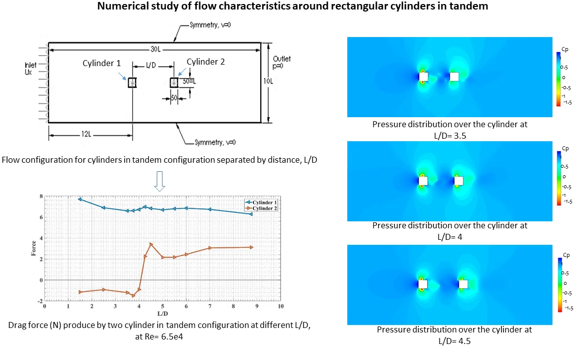
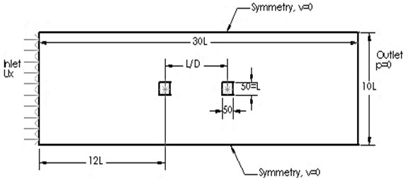
To measure the pressure distribution around the two square cylinder arranged in tandem where dimension of each cylinder was 50 mm×50 mm, a rectangular symmetric domain having length of 30 and height of 10 where, is the edge length of the cylinder, is considered for the fluid zone in the present study as shown in Fig. 1. The Cartesian co-ordinate system is considered and the origin is at the center of upstream cylinder, which is located in (12D, 5D) from the inlet of the domain, which is the center of the upstream square cylinder. Two square cylinder of same edge length are placed in the tandem position. The center to center distance varying considering the upstream cylinder fixed and / varies with the movement of the downstream to right hand side.
Fig. 1Flow configuration for cylinders in tandem configuration separated by distance, L/D
3. Mathematical model
The SST - model is used, which is an empirical model based on transport equation for the turbulence kinetic energy () and the specific dissipation rate (), which are obtained from the following transport equation:
In the equation, represents the generation of turbulence kinetic energy due to mean velocity gradients, represents the generation of , and represents the effective diffusivity of and respectively.
For turbulent flow, the - and - model is popular for simulating single phase flows at high Reynolds number. The equation of Reynolds number ( as follow:
where, is the characteristics length of the body. In the realizable - model, the turbulence effects are modeled using the realizable two equation - model, flow close to the wall modeled using wall functions, which offers a poor result close to wall region [11]. Whereas, the - model can resolve the flow all the way down to the wall [12]. In the present study, for turbulent flow, SST - model is used, the SST - model is so-called low Reynolds number model, which shows the similar accuracy like - model. The model depends on the distance to the closest wall [13].
The effective diffusivities for the SST - are given by:
where, and are the turbulent Prandtl number for and respectively. The term represents the production of turbulence kinetic energy, defined as follow:
And the term represents the production of and is given by:
4. Numerical model
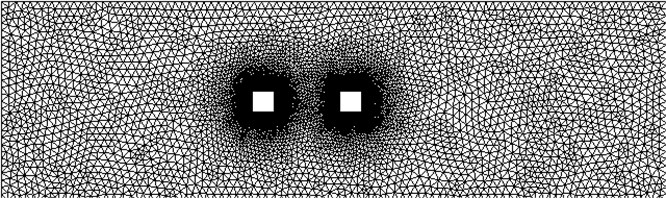
Since the mean pressure distribution around the rectangular cylinders are observed, the computational region is discretized in such a way extremely fine triangular mesh in generated around the cylinders, so that the change of velocity and pressure around them observed closely. Fig. 2 shows the mesh grid system.
Fig. 2Mesh grid system
5. Results and discussions
Effect of interspacing between the cylinders was observed by changing the ratio of /. Simulations are carried out at high Reynolds number of 6.5e4.
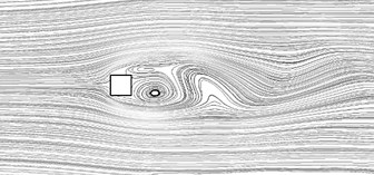
Fig. 3(a) and Fig. 4(a) shows the streamline and pressure contour for the single square cylinder. It is seen that the spread of the wake increases as the distance from the body is increased and the difference between the pressure in the wake and that outside become smaller such a spread of a wake is logical from the point of view of energy transfer to the wake from the surrounding. The pressure of body in the cylinder section reduces the flow area and thereby increases the velocity of air as it flows around the body. This increase of velocity due to the presence of the body is called solid blocking. The wake behind a body has a mean velocity lower than the free stream.
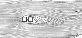
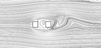
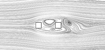
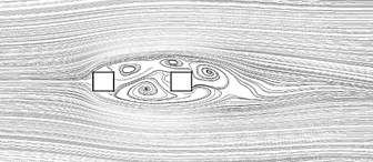
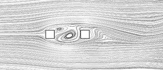
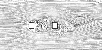
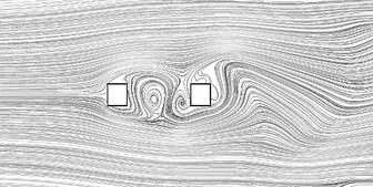
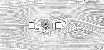
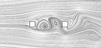
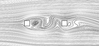
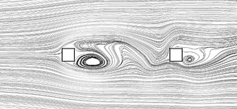
Fig. 3Time averaged streamline for square cylinders arranged in tandem at Re = 6.5e4 for different L/D: a) single cylinder, b) L/D= 1.5, c) L/D= 2.5, d) L/D= 3.5, e) L/D= 3.75, f) L/D= 4, g) L/D= 4.25, h) L/D= 4.5, i) L/D= 5, j) L/D= 6, k) L/D= 7, l) L/D= 8.75
a)
b)
c)
d)
e)
f)
g)
h)
i)
j)
k)
l)
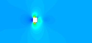
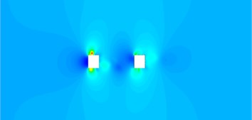
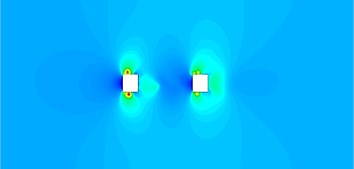
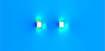
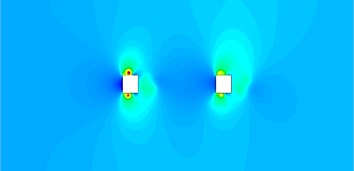
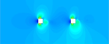
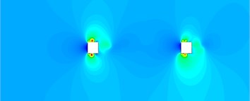
Fig. 4Time averaged streamline for square cylinders arranged in tandem at Re=6.5e4 for different L/D, a) single cylinder, b) L/D= 1.5, c) L/D= 2.5, d) L/D= 3.5, e) L/D= 3.75, f) L/D= 4, g) L/D= 4.25, h) L/D= 4.5, i) L/D= 5, j) L/D= 6, k) L/D= 7, l) L/D= 8.75
a)
b)


c)
d)

e)
f)
g)
h)

i)
j)

k)
l)

Fig. 3(b-l) shows the time averaged streamline in the wake behind upstream and downstream cylinders arranged in tandem for different spacing. It can be seen that for spacing up to 4 the velocity profile in the wake of the upstream cylinder are similar. The velocity defect is considerably large behind the upstream cylinder for 4. Also, there is not much change in the half width. However, for 4 the velocity defect behind the upstream cylinder becomes smaller and gradually decreases with increase in longitudinal distance. And the shape of the profile becomes more or less similar to that of single cylinder. For the downstream cylinder however the nature of the velocity profile is more or less similar to that of a single cylinder for all longitudinal spacing.
Fig. 3(d-f) shows the mean velocity distribution behind upstream cylinder for longitudinal spacing 3.5 to 4. It can be seen that the width of the velocity profile does not change throughout the length of the velocity defect and it assumes a rectangular shape rather than a triangular shape. And Fig. 3(g-l) shows the velocity profile after 4.25 to 8.75, it is observed from the figures that the shape of the velocity profile is similar to that of a single cylinder.
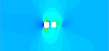
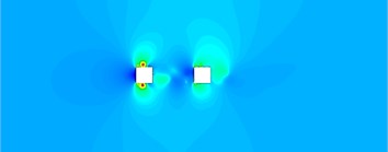
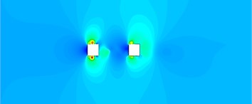
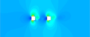
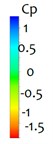
Fig. 4(a-l) shows the pressure contours over the square single cylinder and cylinders at tandem configuration in different interspacing. In the case of a shape body like a square cylinder the separation points are fixed at the leading edges (corners of the front face) and thus the shear layers originating at the front corner outward, which causing vortex formation in the wake region behind the body. The growing vortices draw in fluid from the base region and it is suggested that it is this continual entrainment process that suction the low negative pressure. Thus, a low base pressure is associated with vortex formation close to the body while a high base (less negative value) is caused by vortex formation further away. In the present case for 4 the pressure of the downstream cylinder close to the upstream cylinder causes the separated boundary layers of the upstream cylinder to be deflected further downstream cylinder and as a result the vortices are formed further away from the rear face of the downstream cylinders. For 4, both cylinders are shedding vortices, the pressure distribution at the rear side of the downstream cylinder is lower than the front pressure and thus subjected to a positive drag.
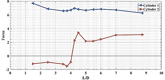
From Fig. 5, it is seen that for the downstream cylinder negative drag exists for 4, however when 4 positive drag occurs. This pressure profile was also found in tandem jets by Hossain [14]. This profile explains that when 4 the boundary layers that separate from the upstream cylinder reattach on to the downstream cylinder and a region of slow moving fluid is formed which is bounded by the shear layers and the two cylinders. The bounded region is at a pressure that is lower than the wake pressure of the downstream cylinder and hence the latter is subjected to a negative drag force or thrust.
Fig. 5Drag force produce by two cylinder in tandem configuration at different L/D, at Re= 6.5e4
6. Conclusions
The effect of flow characteristics around square cylinders in tandem is analyzed is presented. It is being observed that 4 is the critical spacing which effects the pressure distribution and aerodynamic forces on both cylinders.
1) For 4, the pressure on the front surface of the downstream cylinder is much lower than the wake pressure of the same cylinder.
2) Beyond, 4 the front surface pressure rises above that of the back surface pressure.
3) When 4, the downstream cylinder is subjected to negative drag and at 4 positive drag occurs.
4) The width of the velocity profile does not change throughout the length of the velocity defect and it assumes a rectangular shape rather than a triangular shape when 4, half width increases with the increase of axial distance.
References
-
Ozdil Filiz Tumen N., Akilli Huseyin Flow comparison around horizontal single and tandem cylinders at different immersion elevation. Ocean Engineering, Vol. 189, 2019, p. 106352.
-
Mithun M. G., Shaligram T. Flow past two tandem square cylinders vibrating transversely in phase. The Japan society of fluid mechanics. Fluid Dynamics Research, Vol. 46, Issue 5, 2015, p. 055509.
-
Bearman P. W., Trueman D. M. An investigation of the flow around rectangular cylinders. The Aeronautical Quarterly, Vol. 23, Issue 3, 1972, p. 229-237.
-
Igarashi T. Characteristics of the flow around four circular cylinders arranged in line. Bulletin of JSME, Vol. 29, Issue 249, 1986, p. 751-757.
-
Dilip Maiti K., Rajesh Bhatt Numerical study on flow and aerodynamic characteristics: square cylinder and eddy-promoting rectangular cylinder in tandem near wall. Aerospace Science and Technology, AESCTE-3037, 2014.
-
Palau Salvador G., Stoesser T., Rodi W. LES of the flow around two cylinders in tandem. Journal of Fluids and Structures, Vol. 24, 2008, p. 1304-1312.
-
Lin J. C., Yang Y., Rockwell D. Flow past two cylinders in tandem: Instantaneous and averaged flow structure. Journal of Fluid and Structures, Vol. 16, Issue 8, 2002, p. 1059-1071.
-
Zhou Y., Yiu M. W. Flow structure, momentum and heat transport in a two-tandem-cylinder wake. Journal of Fluid Mechanics, Vol. 548, 2006, p. 17-48.
-
Wang X. K., Hao Z., Zhang J. X, Tan S. K. Flow around two tandem square cylinders near a plane wall. Experiments in Fluids, Vol. 55, Issue 1, 2014, p. 1818.
-
Wang L. J., Md. Mahbub Alam, Zhou Y. Wake and vortex-shedding from different diameter cylinders in tandem. Proceedings of the 3rd Symposium on Fluid-Structure-Sound Interactions and Control, 2016, p. 421-427.
-
Jones W. P., Launder B. E. The prediction of linearization with a two-equation model of turbulence. Journal of Heat and Mass transfer, Vol. 15, Issue 2, 1972, p. 301-314.
-
Menter F. R. Zonal two equation k-ω turbulence model for aerodynamic flows. 24th AIAA Fluid Dynamics Conference, 1993.
-
Menter F. R. Two equation eddy-viscosity turbulence models for engineering applications. AIAA Journal, Vol. 32, Issue 8, 2012, https://doi.org/10.2514/3.12149.
-
Mosharrof H. Flow Characteristics Around Rectangular Cylinders in Tandem. Master’s Thesis, Bangladesh University of Engineering and Technology (BUET), Dhaka, Bangladesh.
Cited by
About this article

