Abstract
To get better understanding of vortex shedding mechanism, we conducted numerical simulation on NACA 4418 hydrofoil at an angle of attack of 12° for 2D incompressible flow. The numerical method consists of transient, finite volume method using Transient SST turbulent model to capture the turbulent wake flows. At high Reynolds number the occurrence of 2D structures of shed vortices and the modulation of vortex-induced frequency are investigated. The lift, pressure and skin friction coefficients of hydrofoil were studied.
1. Introduction
Flow over a two-dimensional hydrofoil shows different hydrodynamics and flow dynamics characteristics which basically depends upon the shape of hydrofoil and free stream parameters.
The shape and the angle of attack of hydrofoil determines the pressure distribution which corresponds to the change in lift and drag forces [1]. The parameters which influences the flow dynamics are Mach number, angle of attack (AOA) and Reynolds number [2]. At low Reynolds number and at small AOA the flow remains laminar near the leading edge of hydrofoil but at higher Reynolds number and increasing AOA the fluid starts to segregate near the rear edge forming vortices. The trailing edge separation moves upstream, and the separated flow grows with increasing angle of attack. This flow separation and formation of vortices make the flow oscillating and this phenomenon is called vortex shedding.
The phenomenon of vortex shedding can be seen everywhere near us such as: wind flow around driving car, ocean current interaction with offshore structures, on aircrafts. Leonardo da Vinci was the first one to describe concept of vortex formation in a flow around bluff bodies. Vortex are the rotating or swirl occurs when the water current is hinders by an obstruction, often turbulent flow [3, 4]. The major difficulty to simulate these flows lies in capturing the complex behaviour of the oscillating flow. However, with the emergence of powerful computers, computational methods like finite difference method (FDM), finite volume method (FVM), finite elements method (FEM) it became easy to investigate various fluid dynamics problems. It has been observed that vortex shedding is unsteady flow which produces separate stream along most of the surface [5].
In this work the transient turbulent flow over a NACA4418 hydrofoil profile at 99700 and angle of attack 12° is simulated using a finite volume method (FVM) in Ansys Fluent. The pressure coefficient and skin friction coefficient were computed as function of chord length of hydrofoil. The purpose of this paper is to study the physics behind the vortex shedding for transient simulations.
2. Governing equations
The movement of 2-D viscous incompressible fluid flow over the hydrofoil is governed by the continuity equation and Navier-Stokes equations:
where / is the Reynolds number, is the velocity in -direction and is the velocity in -direction, is the mass density, is the kinematic viscosity, is the time, is the pressure and is initial value of velocity provided at the inlet along with zero relative velocity to boundary condition on the solid walls [6, 7]. To solve the external flows, suitable initial boundary conditions must be provided to start the solution. Lifting bodies like hydrofoil are designed to provide large forces in the direction of perpendicular to direction of flow and low drag. The coefficient of drag , coefficient of lift.
, Strouhal number coefficient of pressure , skin friction coefficient and vorticity on solid body are defined as following:
where and is lift and drag force respectively whereas, is the characteristic dimension, is frequency if oscillations and is the chord length of hydrofoil.
2.1. Turbulent model
Transition shear stress transport (SST) model is being used for transient simulation that basically defines the coupling of SST - equation with other two transport equations, one is used for intermittency and other for the transition onset standard, with respect to Reynolds number for momentum-thickness [8]. The Transition SST model is designed for flows with a defined non-zero freestream velocity. The local turbulence intensity, with as the turbulent energy is as below:
3. Computational procedure
3.1. Geometry formation and mesh generation
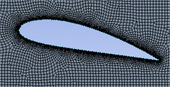
The steady and transient two-dimensional flow over NACA4418 hydrofoil at an angle of attack (AOA) of 12° was simulated using finite volume method (FVM) code in Ansys Fluent. To generate the profile of hydrofoil NACA airfoil generator database is being used. Two types of meshes were considered in this work. One was C-mesh type, which is multiblock structure mesh that consists of semicircle grid that follows the hydrofoil geometry on leading edge and other is rectangular grid which captures the trailing edge physics. C-mesh provides the advantage of fine grids in the higher resolution regions [9]. To obtain as many cells near the hydrofoil edge sizing is applied which results in more accurate computation in the region where the gradients are more pronounced which is basically captures the vortex generation. The transient simulation at Re no 99700 were performed with linear upwind FVM in Ansys Fluent using SIMPLE algorithm for velocity-pressure coupling [10, 11].
Fig. 1NACA 4418 profile at ∝= 12°
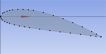
Fig. 2Structured C-mesh close to hydrofoil
3.2. Initial and boundary conditions
In order to simulate the motion of fluid from rest some initial value of free stream velocity ( 1 m/s) is given at the inlet boundary, and other boundary conditions used in Ansys Fluent are as follows:
Table 1Boundary conditions at different locations
Boundary | Boundary conditions |
Inlet | Velocity inlet |
Outlet | Pressure-outlet |
Upper-wall | No-slip wall |
Lower-wall | No-slip wall |
Hydrofoil | No-slip wall |
Once mesh was generated along with boundary conditions, the incompressible Navier-Stokes equations were discretized using Transition Shear Stress Transport (SST-4 equation) model and for pressure-velocity coupling SIMPLE method was used. One the velocity and pressure fields were computed the results were post-processed to compute the vorticity field as well as lift, drag, pressure and skin friction coefficients.
4. Results and discussion
Computational flow dynamics (CFD) study has been carried out for wide range of flow regimes.
In this study main focus is the numerical transient simulations of 2D flow around NACA 4418 hydrofoil at 12° AOA. Uniform flow with free stream velocity if 1 m/s is used to start the simulation.
4.1. Vortex shedding and 2D instability
Even though most of real-life geometries are three-dimensional in nature but for good understanding of flow separation development, vortex shedding and instability 2D simulations still are considered to be helpful. The 2D simulation is initialized with uniform velocity at inlet with Re no 99700 for transient simulation.
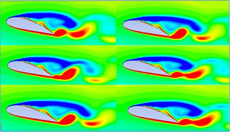
The instantaneous spanwise contours of vorticity after simulation are shown in Fig. 3, where vortex shedding and flow separation can be seen clearly on the suction side of hydrofoil. The separation of flow that begins at the leading edge of the hydrofoil results in separate shear layer which becomes unstable and forms large scale vortices causing vortex-shedding. These vortices are carried to form vortex pair by the mean flow along downstream of hydrofoil surface which considers that vortices are developed due to streamwise growth of perturbation of separate shear layer. The flow near the wake contains strong shear layers due the two flow with opposite vorticity passing over two surfaces of hydrofoil. To understand the time dependency of vortex shedding for the cycle, contour for vortex shedding are simulated for a cycle of 10 seconds.
Fig. 3Vortex shedding at different times (t= 2 sec, t= 4 sec, t= 6 sec, t= 8 sec, t= 10 sec, t= 11 sec)
The result of pressure distribution along the upper surface and lower surface of hydrofoil is shown in Fig. 4. Pressure coefficient simply represents the change in static pressure around the hydrofoil. The minimum pressure often occurs close to leading edge. Using Bernoulli’s for incompressible flow we can say that with increase in local velocity, the pressure coefficient at that place decreases. According to certain flow velocity these pressure variation yields usable range of lift coefficients. In Fig. 5, the skin friction coefficient along the hydrofoil length is shown which is described as the ratio of local shear stress and characteristics dynamic pressure.
Fig. 4Coefficient of pressure versus chord length
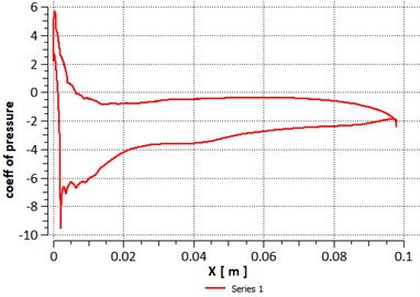
Fig. 5Skin friction coefficient versus chord length
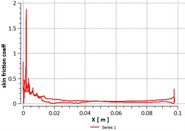
Fig. 6Lift coefficient versus flow time
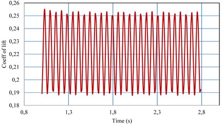
The value of lift coefficient for the time flow is reported in Fig. 6. From the transient computation, the instability occurs after few iterations and it converge to fully periodic flow with shedding of vortex structures.
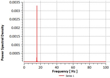
At an angle of 12°, the vortex shedding becomes increasingly disorganized and this irregular shedding describes the periodicity of oscillatory forces. Fig. 7. shows the power spectral density function (PSD) of lift coefficients. We can observe the first peak value of PSD at frequency of 15 Hz. From the vibration viewpoint, the forcing frequency is important for prevention of resonance.
Fig. 7Power spectral density of lift coefficient versus frequency normalized by the chord length
5. Conclusions
We simulated incompressible flow past a NACA 4418 hydrofoil at Reynolds Number of 99700, using the Transient SST (DES) model in conjunction with SIMPLE pressure-velocity coupling method. We have achieved significant savings in both memory usage and computation time by using proper numerical scheme.
In this study, the numerical simulation demonstrates the vortex shedding of a 2D hydrofoil at an angle of 12° with respect to sinusoidal motions of free stream flow. Magnitude of free stream velocity was kept constant. With two- dimensionality, it is possible to solve problem easily as 3D problems requires significant computational resources. We found in the study that the vortex formation in periodically varying inflows remains same, as certain frequency of free-stream oscillation tends to make vortex shedding more regular again. However, effect of cavitation on vortex shedding is not yet understood. Future work will include numerical simulation of 2D and 3D hydrofoil to understand the relationship between vortex shedding and cavitation.
References
-
Agromayor Roberto, Rúa Jairo, Kristoffersen Reidar Simulations of starting and stopping vortices of an Airfoil. Linköping Electronic Conference Proceedings, 2017, p. 66-75.
-
Balakumar P. Direct numerical simulation of flows over an NACA-0012 airfoil at low and moderate Reynolds numbers. 47th AIAA Fluid Dynamics Conference, Denver, Colorado, 2017.
-
White F. M. Fluid Mechanics. 8th Edition, McGraw-Hill, 2017.
-
King Roger A review of vortex shedding research and its application. Ocean Engineering, Vol. 4, Issue 3, 1977, p. 141-171.
-
Versteeg H., Malalasekra W. An Introduction to Computational Fluid Dynamics. 2nd Edition, Pearson, 2018.
-
Young D. L., Huang J. L., Eldho T. I. Simulation of laminar vortex shedding flow past cylinders using coupled BEM and FEM model. Computer Methods in Applied Mechanics and Engineering, Vol. 190, 2001, p. 5975-5998.
-
Zhai Zhiqiang, Zhang Zhao, Zhang Wei, Chen Qingyan Evaluation of various turbulence models in predicting airflow and turbulence in enclosed environments by CFD: part 1: summary of prevalent turbulence models. HVAC & R Research, Vol. 13, Issues 6, 2007, p. 853-870.
-
Saatchi D., Fathali M., Khojasteh A. R. The impacts of five different turbulence models on the accuracy of computational aeroacoustics results for an airfoil and acoustic localization analysis for well suited model. International Review of Mechanical Engineering (I.RE.M.E.), Vol. 8, Issue 2, 2014, p. 387-398.
-
Ockfen Alex E., Matveev Konstantin I. Aerodynamics characteristics of NACA 4412 Airfoil section with flap in extreme ground effect. International Journal of Naval Architecture and Ocean Engineering, Vol. 1, Issue 1, 2009, p. 1-12.
-
Ausoni Philippe, Farhat Mohamed, Avellan Francois Hydrofoil roughness effects on von Karman vortex shedding. 2nd International Meeting of the Workgroup on Cavitation and Dynamic Problems in Hydraulic Machinery and Systems Timisoara, Romania, 2007.
-
Yu An, Luo Xianwu, Ji Bin, Huang Renfanh Cavitation simulation with consideration of the viscous effect at large liquid temperature variation. Chinese Physics Letters, 2014.
-
Shan Hua, Jiang Li, Liu Chaoqun Direct numerical simulation of flow separation around a NACA 0012 Airfoil. Computers and Fluids, Vol. 34, 2005, p. 1096-1114.
About this article

