Abstract
In deep sea oil exploitation, offshore structures subjected to winds, waves and currents will cause the connected flexible riser to oscillate in the water, which contributes to complicated Vortex-induced Vibration (VIV) phenomenon. In this paper, VIV of a flexible cylinder under two degree-of-freedoms (Dofs) excitations are mainly investigated. All simulations are carried out by the viv3D-FOAM-SJTU solver, which is developed based on the open-source code OpenFOAM and the thick strip model. During the simulations, the flexible cylinder is forced to sinusoidally oscillate following the approximate “8” shape of trajectory, while the cylinder is allowed to vibrate in both directions. Modal decomposition method and wavelet transformation method are used to get the dominant vibration features of the cylinder. Variations on vortex structures of the cylinder are analyzed through the three-dimensional visualization method.
Highlights
- Simulations on VIV of a flexible cylinder is conducted by the three-dimensional strip model.
- The typical “upward convex” shape of vibration feature is observed.
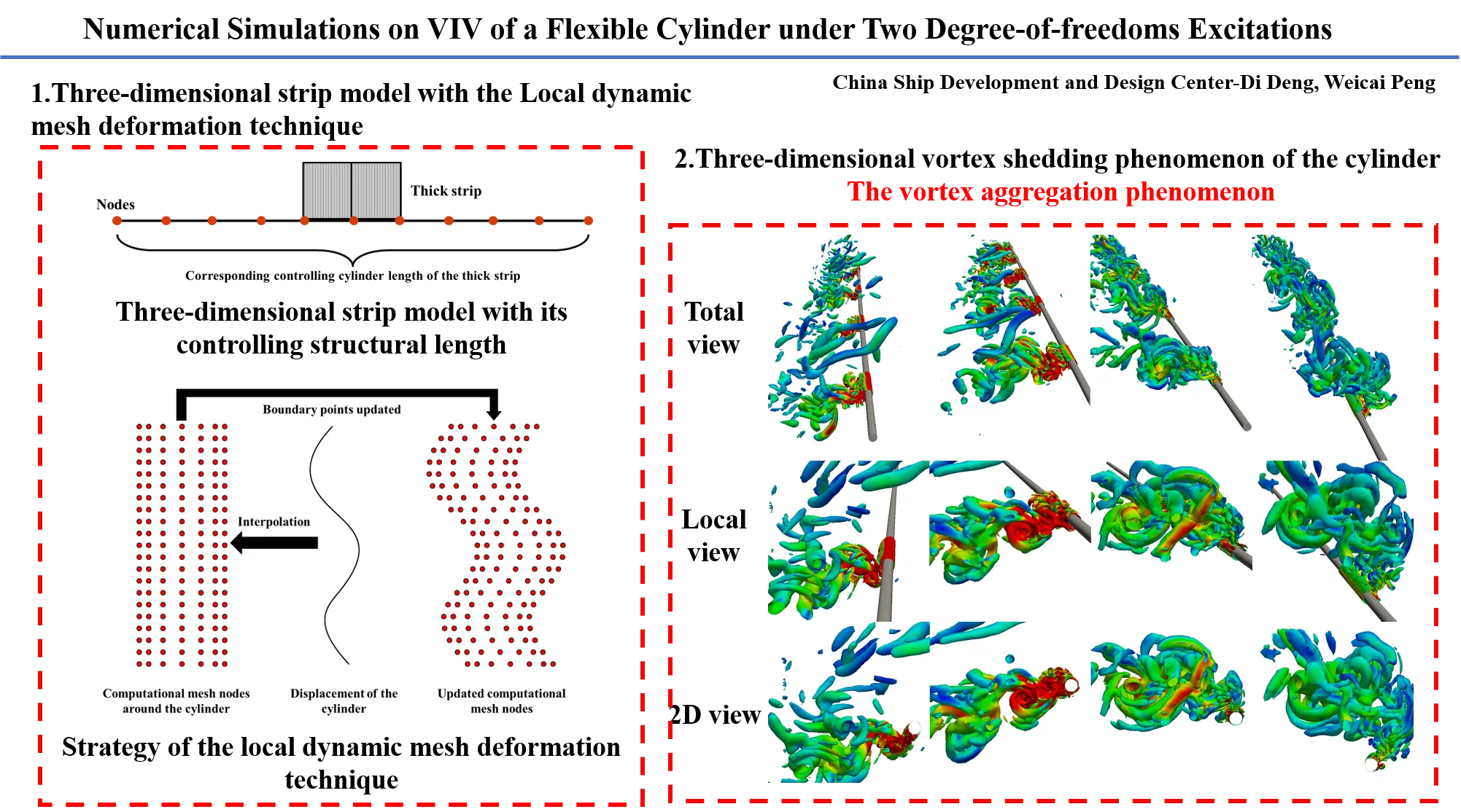
- Vortex aggregation phenomenon is observed in the cavity of the two-Dofs excitation trajectory.
1. Introduction
In actual ocean environment, offshore platforms may periodically oscillate under the effects of winds, waves and currents, which will excite the connected risers to oscillate in the water simultaneously and result in the complicated VIV phenomenon. In former research, Fu et al. [1] and Wang et al. [2] conducted a series of experiments on VIV of a flexible cylinder in the oscillatory flow with KC numbers ranging from 26 to 178. The typical VIV developing process of “building up”, “lock in” and “dying out” was proposed, which generated the intermittent VIV phenomenon. Due to the interaction between the cylinder and the wake flow, vortex shedding, and vibration characteristics of the cylinder changed obviously.
In terms of numerical studies, Yuan et al. [3] proposed a semiempirical VIV predicting model considering the horizontal excitations of the cylinder. Fu et al. [4] introduced an oscillating excitation module to the viv-FOAM-SJTU solver and realized the numerical prediction on VIV of a flexible cylinder under the one-Dof oscillatory excitation. Further, Fu and Wan [5] carried out simulations on VIV of a flexible cylinder under two-Dofs horizontal excitations, which was only applied to the top end of the cylinder. The complex crown shape of vibration trajectory was observed.
In this paper, numerical simulations are carried out by the viv3D-FOAM-SJTU solver. Effects of oscillatory amplitude ratios on VIV responses of the flexible cylinder are mainly studied. The numerical method is introduced in Section 2. The validation study and the simulation results are illustrated in Section 3 and Section 4. Finally, a brief conclusion is given in Section 5.
2. Numerical method
2.1. Hydrodynamic governing equations
The Reynolds-averaged Navier-Stokes (RANS) equations are used to solve the incompressible and viscous flow field in each thick fluid strip. The continuity and the momentum equations for turbulent flow are written as Eq. (1) and Eq. (2):
where is the constant dynamic viscosity; is the constant density; is the Reynolds stress generated by the pulsation velocity. It is necessary to introduce corresponding turbulence model to close the equation. The SST - turbulence model proposed by Menter [6] is adopted to compute the Reynolds stress, which is a hybrid model according to the - turbulence model and the - turbulence model.
2.2. Structural governing equations
The forced oscillatory excitations at both ends of the cylinder in the inline and crossflow directions can be expressed as follows:
where and are time history displacements; and are oscillatory amplitudes; and are oscillatory periods in inline and crossflow directions respectively; is the phase angle.
The flexible cylinder is assumed to be a Euler-Bernoulli bending beam with an axial pretension. Vibrations of the model are solved through the FEM method with corresponding governing equations written as followed:
where is the structural stiffness of the cylinder; is the axial tension; is the element mass; is the structural damping; and are inline and crossflow hydrodynamic forces. Meanwhile, the Rayleigh damping is adopted to replace the practical damping.
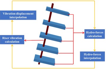
2.3. Thick strip model
The schematic diagram of the thick strip theory is shown in Fig. 1, which was proposed by Bao et al. [7]. The thick strip model solves disadvantages of the traditional 2D strip model through considering the local 3D features of the flow field in each thick strip. This method has been validated by Bao et al. [8].
In each time step, hydrodynamic forces are calculated and transferred into uniformly distributed loads at each thick strip. Then, these loads are applied to the corresponding structural elements through the cubic spline interpolation method. Meanwhile, vibrations of the cylinder are calculated using the Newmark- algorithm. Finally, vibration displacements at each node can be obtained, which will be used to update the computational mesh using the dynamic grid technique.
Fig. 1The schematic diagram of the thick strip theory
3. Simulation setup
The mesh convergency and validation studies have been carried out by Deng et al. [9], where a flexible cylinder was excited to oscillate in the inline direction based on experiments of Wang et al. [2]. Main parameters of the cylinder and the simulation condition are shown in Table 1. The computational model is shown in Fig. 2, which is modified from the computational model of Deng et al. [9]. Five thick fluid strips are uniformly distributed along the cylinder span with all strips sharing the same computational domain and boundary conditions. Each fluid strip is 120D in both directions and /25 in the axial direction. The mesh near the cylinder surface is refined and keeps the yPlus around 3.0 to calculate hydrodynamic forces correctly with no wall function used in all simulations. In order to control the total grid quantity, two quadrate regions near the cylinder are chosen to refine the mesh and keep the mesh resolution the same as Fig. 2(b).
Fig. 2Schematic diagram of the computational model
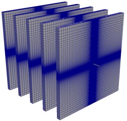
a) Computational model
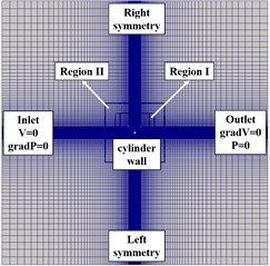
b) Boundary conditions
Table 1Main parameters and the corresponding condition of the flexible cylinder
Properties | Values | Unit | |
Mass ratio | 1.53 | – | |
Diameter | 24 | mm | |
Length | 4 | m | |
Structural stiffness | 10.5 | Nm2 | |
Pretension | 500 | N | |
Oscillatory period | 7.5 | s |
The inline oscillatory amplitude and period keep 0.32 m and 7.5 s respectively. While the crossflow oscillatory amplitude increases from 0.02 m to 0.08 m, which contributes to the increase of crossflow KC number from 5.25 (Case 1) to 21 (Case 2). The crossflow oscillation period keeps 3.75 s an all simulations. With the decrease of the amplitude ratio (/), the oscillatory shape varies from the thin “8” shape that is similar to the one-Dof oscillatory shape to the standard “8” shape.
4. Results
4.1. Vibration characteristics
The modal decomposition method is used to analyze modal features of the cylinder. Fig. 3 presents the time history non-dimensional modal weights of the cylinder in the crossflow direction among one-Dof excitation from Deng et al. (2020) and two-Dofs oscillations.
Fig. 3Time history non-dimensional crossflow modal weights of the cylinder
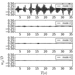
a) Deng et al. (2020)
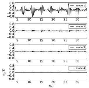
b) Case 1
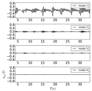
c) Case 2
It can be found that dominant vibration modes keep the 1st mode in all simulations, while comparatively apparent 2nd modal responses only appear in the “lock in” region. However, modal weights of the 2nd mode are obviously smaller than the 1st mode, which make it unable to affect the main vibration characteristics of the cylinder. Meanwhile, modal weights of the 3rd and above modes are too small that can be ignored during the analysis. In Fig. 3(b), the time-history variation trend of the 1st modal weight is similar to the variation tendency in Fig. 3(a), indicating that the crossflow excitation plays little influence on the crossflow vibration response of the cylinder when the oscillatory amplitude ratios are 16. The time-history curves of the 1st modal weights present the typical “upward convex” shape when the oscillatory amplitude ratio decreases to 4 as shown in Fig. 3(c), which indicates that the influence from the crossflow oscillatory excitation has been significantly enhanced. But it still unable to change the dominant crossflow vibration modes of cylinder. Considering the structural characteristics of the cylinder itself, two points can be summarized as follows: first, the crossflow oscillatory excitation is still weak that unable to excite the 2nd vibration mode of the cylinder; Second, the aspect ratio of the cylinder is small that makes it difficult to generate high modal vibration features.
Fig. 4 present wavelet contours at the intermediate node of the cylinder in the crossflow direction. It can be found that the crossflow frequency response of the cylinder also presents obvious intermittent feature. When the oscillatory amplitude ratio is 16, the dominant crossflow frequency response of the cylinder varies from 1.94 Hz to 2.56 Hz, which is similar to the frequency response in Deng et al. [9]. With the decrease of the oscillatory amplitude ratio to 4, the frequency response regions are 2.1 Hz to 2.87 Hz. It can be concluded that the crossflow frequency spectrum width of the cylinder firstly increases and then decreases with the enhancement of the crossflow oscillatory excitation.
Fig. 4Crossflow wavelet contours at the intermediate node of the cylinder
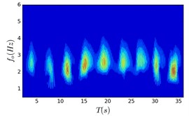
a) Deng et al (2020)
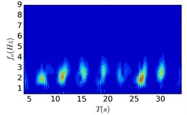
b) Case 1
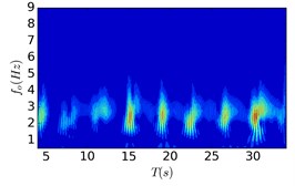
c) Case 2
4.2. Wake flow characteristics
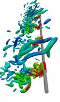
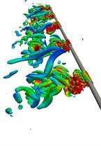
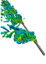
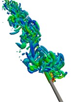
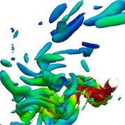
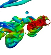
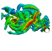
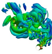
Fig. 5 shows the instantaneous 3D vorticity contours of cylinder (5) in a half oscillatory period when the amplitude ratio is 4. The alternating vortex shedding phenomenon can be observed in the whole oscillatory process, and elongated vortices occupy the main position in the wake flow.
Fig. 5Instantaneous wake structures at the intermediate strip of the riser in half an oscillating period (Q= 5) Case 2
a)29.95 s
b)30.75 s
c)31.75 s
d)32.55 s
e)29.95 s
f)30.75 s
g)31.75 s
h)32.55 s

Because there is no interaction between the shedding vortex and the newly generated vortex on the cylinder surface in the wake flow, the generation of small discrete vortices is significantly reduced. Based on Fig. 5(e) to (h), it can be seen that the wake flow development direction of the cylinder is consistent with the two-Dofs oscillatory trajectory. During the reverse region, the inline oscillatory velocity tends to be 0 and the crossflow oscillatory velocity reaches its maximum, which guarantees enough space for the newly generated vortices to shed immediately without appearing vortex interaction phenomenon in the wake flow. And the obvious vortex aggregation phenomenon can be observed at the cavity of the “8” shape of oscillatory trajectory as shown in Fig. 5(d) and (h).
5. Conclusions
Numerical simulations on VIV of a flexible cylinder under two-Dofs oscillatory excitations with different amplitude ratios are conducted in this paper. The typical “upward convex” shape of vibration response is observed especially when the amplitude ratio is small, while the dominant vibration modes keep the 1st mode in the crossflow direction and the intermittent VIV feature keeps unchanged. With the increase of the amplitude ratio, the width of the vibration frequency spectrum increases firstly and then decreases. An obvious vortex aggregation phenomenon is observed when the amplitude ratio is lower than 5.3 in the cavity of the “8” shape of oscillatory trajectory. While the wake flow become more complicated due to the interaction between newly shed vortices from the cylinder surface and existed vortices from the previous half oscillatory period.
References
-
S. Fu, Y. Xu, K. Hu, and Y. Zhang, “Experimental investigation on hydrodynamics of floating cylinder in oscillatory and steady flows by forced oscillation test,” Marine Structures, Vol. 34, pp. 41–55, Dec. 2013, https://doi.org/10.1016/j.marstruc.2013.08.005
-
Wang Jungao, Fu Shixiao, Xu Yuwang, and Song Leijian, “VIV developing process of a flexible cylinder under oscillatory floW,” Chinese Journal of Theoretical and Applied Mechanics, Vol. 46, No. 2, pp. 173–182, Mar. 2014, https://doi.org/10.6052/0459-1879-13-277
-
Yuchao Yuan, Hong-Xiang Xue, and Wenyong Tang, “Numerical analysis of Vortex-Induced vibration for flexible risers under steady and oscillatory flows,” Ocean Engineering, Vol. 148, pp. 548–562, 2018.
-
B. Fu, L. Zou, and D. Wan, “Numerical study of vortex-induced vibrations of a flexible cylinder in an oscillatory flow,” Journal of Fluids and Structures, Vol. 77, pp. 170–181, Feb. 2018, https://doi.org/10.1016/j.jfluidstructs.2017.12.006
-
B. Fu and D. Wan, “Numerical study of vibrations of a vertical tension riser excited at the top end,” Journal of Ocean Engineering and Science, Vol. 2, No. 4, pp. 268–278, Dec. 2017, https://doi.org/10.1016/j.joes.2017.09.001
-
F. Menter, “Zonal two equation k-w turbulence models for aerodynamic flows,” in 23rd Fluid Dynamics, Plasmadynamics, and Lasers Conference, Jul. 1993, https://doi.org/10.2514/6.1993-2906
-
Y. Bao, R. Palacios, M. Graham, and S. Sherwin, “Generalized thick strip modelling for vortex-induced vibration of long flexible cylinders,” Journal of Computational Physics, Vol. 321, pp. 1079–1097, Sep. 2016, https://doi.org/10.1016/j.jcp.2016.05.062
-
Y. Bao et al., “Numerical prediction of vortex-induced vibration of flexible riser with thick strip method,” Journal of Fluids and Structures, Vol. 89, pp. 166–173, Aug. 2019, https://doi.org/10.1016/j.jfluidstructs.2019.02.010
-
D. Deng, Weiwen Zhao, and D. Wan, “Numerical investigations of VIV of a flexible cylinder in oscillatory flows by thick strip model,” in Proceedings of the Fourteenth (2020) ISOPE Pacific-Asia Offshore Mechanics Symposium, pp. 229–235, 2020.
About this article

