Abstract
A study regarding the effectiveness of non-linear fluid viscous dampers in controlling the wind-induced vibration on buildings is presented. For this purpose, a 28-story building with a large area exposed to wind is designed in two different ways: a) conventionally (without supplemental damping), and b) using non-linear fluid viscous dissipating devices. The building is subjected to 10 groups of simulated wind velocities, where each group is composed of 28 wind signals, which are correlated on the building’s height. Results show that the damping system reduces the floor acceleration by 6.5 and 10.3 times with respect to that of the conventional building, for wind speeds associated with return periods of 10-years and 50-years, respectively. For the case of the building with energy dissipating devices, the floor accelerations result lower than the perception thresholds specified in the literature.
1. Introduction
The structural design of medium and high-rise buildings in Mexico City is dominated normally by the effect of lateral forces caused by earthquakes; however, for tall buildings with a very large exposed area or with particular geometric shapes, the wind action could become significant from the point of view of the design of non-structural components and the comfort of its occupants.
Recent studies [1, 2] show that excessive vibrations induced by intense winds could cause discomfort and even interrupt the occupant’s activities. On the other hand, it is known that the floor acceleration is related to the perception control of these motions. The same investigations address the study of maximum thresholds of floor acceleration to avoid the perceptions of the wind induced motions. These are established as a function of the vibration frequency and of the type of occupancy of the structural system.
There are different alternatives to improve the performance of structures subjected to wind actions. For example, the use of tuned mass dampers, which modify the structural response [3-6]; and of energy dissipating devices (EDD), which increase the damping of the structural system [7, 8]. This study deals with the use of non-linear fluid viscous dampers as a vibrations control system. The structural design is carried out considering the seismic actions, and then, wind-induced vibrations effects are evaluated. Nowadays, there are guidelines for the seismic design of structural systems equipped with energy dissipating devices [9-11]. A detailed review of some of the most important design codes can be found in [12].
2. Methodology
The methodology followed here is described briefly in the subsequent steps:
1) Structural design. The building is designed in a conventional way (CB), and alternatively, with energy dissipating devices (EDB); the design is carried out considering both seismic and wind actions.
2) Dynamic loads. A set of wind velocity signals is simulated according to a power spectral density function that represents the distribution of the wind energy on the height of the building, and to a mean wind speed profile, which considers the topographic local conditions and the ground surface roughness.
3) Time history dynamic analysis. Both versions of the building (with and, alternatively, without EDD) are analyzed, using the set of signals obtained in step 2. The acceleration response is estimated, and then it is compared with the tolerable limits specified in reference [2]. The perception thresholds are associated with the following values of acceleration:
a) Not perceptible, for floor accelerations smaller than 5 mili-g,
b) Perceptible, for floor accelerations from 5 mili-g to 10 mili-g,
c) Strongly perceptible, for floor accelerations from 10 to 25 mili-g.
3. Illustration of the methodology
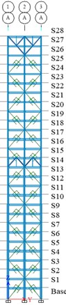
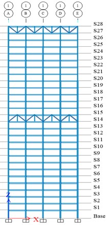
The two versions of the building under study are composed of composite steel and concrete moment-resisting frames. The first version of the building was designed in a conventional way in accordance with the specifications of the Mexican Complementary Technical Norms for Seismic Design (NTCDS-2017). Figs. 1 and 2 show the plan of the building, the elevation on axis 1, and the elevation on axis A, respectively. The second version of the building has the same geometric characteristics as the first version, but it is equipped with 56 non-linear fluid viscous dampers in the axis A and E. For the design of the second version of the building, Guidelines of the NTCDS-2017 and some from Chapter 18 of ASCE/SEI 7/16 [11] were followed.
Fig. 1Plan of the building
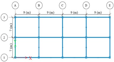
Fig. 2Elevation on Axis 1 and Axis A
a)
b)
3.1. Structural design
Seismic actions.
For the structural design, a pseudo-acceleration design spectrum corresponding to the intermediate soil of Mexico City (with a dominant period 1 s) was considered. The following parameters were taken into account (from NTCDS-2017):
For the conventional building:
• A seismic behavior factor 2 as well as an over-strength factor 2 (it can be shown that the combination of both factors is similar to the response modification coefficient, , specified in ASCE/SEI 7-16).
• Permissible inter-story drift of 0.015 for the collapse prevention limit state, and of 0.004 for the serviceability limit state.
For the building equipped with energy dissipating devices:
• A preliminary design was performed using a damping reduction factor 0.52 [10, 13], which is equivalent to reduce the seismic design spectrum by 22 % of critical damping.
• The final structural design was verified using non-linear time history analyses.
Wind Actions.
The basic parameters used for wind design, according to NTCDS-2017 and Manual of Civil Structures-Wind Design (MCS-2008) [14], are the following:
• Basic design wind speed, 31 m/s (associated with a return period = 50 years).
• Basic design wind speed corresponding to the serviceability limit state 20 m/s (associated with a return period = 10 years). Topographic effect type = 3 (flatland).
• Exposure category type R4 (ground surface roughness corresponding to buildings taller than 20 m).
• The dynamic amplification factor is calculated according to the Complementary Technical Norms for Wind Design of the Mexico City Building Code (NTCDV-2017).
3.2. Wind velocity signals
Wind velocity signals were simulated with the software SVTpro [15] which uses an Autoregressive Moving Average Model (ARMA) [16]. The software correlates the wind velocity signal along the building height. Ten sets of wind speed signals were developed for the analysis; each set is composed by 28 wind speeds time histories with 600 seconds duration. The mean wind velocity profile of the site and the Kaimal power spectral density function (PSD) according to MCS-2008 [14] are used to simulate the wind velocity signals. Fig. 3(a) shows the Kaimal PSD, while in Fig. 3(b) is depicted the wind velocity profile, as well as two generated velocity signals, at 10 m and 114 m from the ground. It is noted that these two velocity signals correspond to one of the simulations.
Fig. 3Wind velocity signals considering correlation on the height of the building
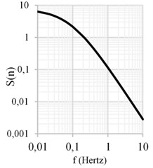
a) Normalized Kaimal power spectral density
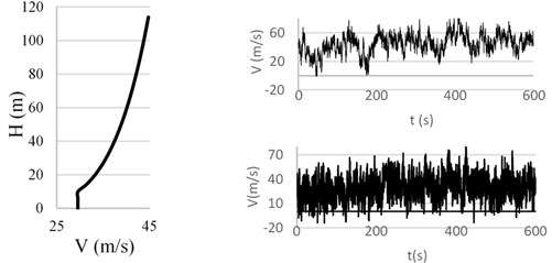
b) Wind speed profile CDMX and two signals correlated with the height
3.3. Time history analysis
The motion equation for a structural system equipped with a non-linear fluid viscous damping system subjected to lateral forces due to wind is as follows:
where: , , are the mass, inherent damping and stiffness matrices, respectively. is the damping constant vector in which is the damping constant of the devices at the th story; is the damping exponent of the devices at the th story. , are the pressure coefficient and the area exposed to wind, respectively. is the wind velocity matrix associated with the th story and the th intensity duration (s).
The numerical integration of Eq. (1) is carried out using the Etabs [17] software. The following assumptions were considered in the modeling: a) the damping system is explicitly modeled via “link” type elements with a damping constant 980.6 kN (s/mm)αand 0.5; b) the inherent damping of the structural system is modeled through a Rayleigh damping matrix, with 1 % in all its modes [14]; and c) the wind velocity signals were transformed to force histories and were applied at the center of mass of each story diaphragm.
4. Results
The results presented in Figs. 4 to 7 correspond to the direction which has greater exposure to the wind effects. Figs. 4 and 5 show the acceleration response of the 28th story of both versions of the building for two wind velocities associated with return periods of 10 and 50 years, respectively. The associated not perceptible and perceptible acceleration thresholds are shown with dotted lines.
Fig. 4Floor acceleration in the 28th story, third simulation. Return period Tr= 10 years
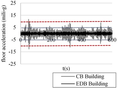
Fig. 5Floor acceleration in the 28th story, third simulation. Return period Tr= 50 years
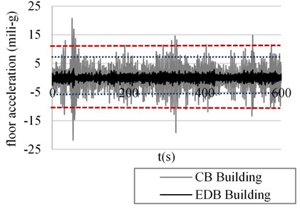
It can be observed in Fig. 4 that for low return periods, the wind generates dragging forces that cause a high response in terms of acceleration, for the CB building. The acceleration values exceed the not perceptible threshold (dotted line) and there are several cycles where the motion is perceptible, which can generate discomfort in the occupants. On the other hand, the EDB building effectively controls the floor acceleration through the damping system and remains below 5 mili-g (the not perceptible acceleration threshold); besides, it can be seen that the response peaks are damped to a greater extent. This is due to the fact that the velocity response of the structural system is also high and generates greater amplitude in the cycles of the damping system. In a similar way, Fig. 5 shows the acceleration response of the CB and EDB buildings for winds associated with a return period of 50 years. It is important to highlight that the CB building exceeds the threshold of 10 mili-g; which indicates that the motion is strongly perceptible and could interrupt the activities inside the building, such as: reading or writing, and consequently, cause discomfort in the occupants [2]. The EDB building remains at acceleration values below 5 mili-g.
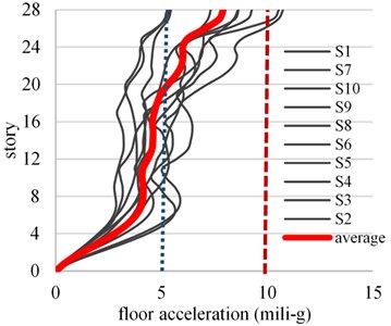
Figs. 6 and 7 show the maximum accelerations profile for the 10 simulations (thin continuous line) and the average of the response in terms of the floor acceleration of each story (thick continuous line). The not perceptible and perceptible acceleration thresholds are depicted with dotted lines. For wind speeds with small return periods (10 years), the average floor acceleration of the CB building exceeds the not perceptible threshold in the 8 upper stories, while for the EDB building the average floor acceleration remains below 1.5 mili-g. Therefore, the damping system could be placed only in the upper stories and evaluate its effects, however, this may have an unfavorable effect on the control of the seismic response. For low frequent wind velocities ( 50 years) the average floor acceleration for the CB building exceeds 10 mili-g from the fourth to the upper stories, while for the EDB building they remain under 5 mili-g for all stories.
Fig. 6Floor acceleration profile for wind speed corresponding to Tr= 10 years
a) CB building
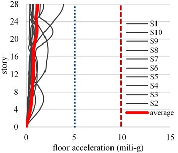
b) EDB building
Fig. 7Floor acceleration profile for wind speed corresponding to Tr= 50 years
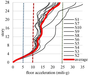
a) CB building
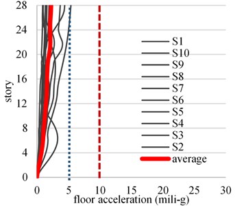
b) EDB building
5. Conclusions
It is concluded that the damping system has a favorable effect on the control of the floor acceleration and it is useful to effectively reduce the perception that could experience the occupants of the building under intense wind velocities. The maximum floor acceleration response of the EDB building was 6.5 and 10.3 times lower than that of the CB building, for wind velocities associated with return periods of 10 years and 50 years, respectively.
References
-
Pozos Estrada A., Hong H. P., Galsworthy J. K. Serviceability design factors for wind-sensitive structures. Canadian Journal of Civil Engineering, Vol. 37, 2010, p. 728-738.
-
Tamura Y., Kawana S., Nakamura O., Kanda J., Nakata S. Evaluation perception of wind-induced vibration in buildings. Proceedings of the Institution of Civil Engineers, Structures and Buildings, Vol. 159, Issue 5, 2006, p. 283-293.
-
Yang J., Agrawal A. K., Samali B., Wu J. Benchmark problem for response control of wind-excited tall buildings. Journal of Engineering Mechanics, Vol. 130, Issue 4, 2004, p. 437-446.
-
Rüdinger F. Tuned mass damper with non-linear viscous damping. Journal of Sound and Vibration, Vol. 300, 2007, p. 932-948.
-
Giaralis A., Petrini F. Wind-induced vibration mitigation in tall buildings using the tuned mass-damper-inerter. Journal of Structural Engineering, Vol. 143, Issue 9, 2017, https://doi.org/10.1061/(ASCE)ST.1943-541X.0001863.
-
Pozos-Estrada A., Hong H. P. Sensitivity analysis of the effectiveness of tuned mass dampers to reduce the wind-induced torsional responses. Latin American Journal of Solids and Structures, Vol. 12, 2015, p. 2520-2538.
-
Zhiqiang Z., Aiqun L., Jianping H., Jianlei W. Wind-induced vibration control of Hefei TV tower with fluid viscous dampers. Frontiers of Architecture and Civil Engineering in China, Vol. 3, 2009, p. 249-254.
-
Santos-Santiago M. A., Ruiz S. E., Valenzuela-Beltrán F. Multihazard risk assessment (seismic and wind) for buildings with dampers in Mexico City. Proceedings of the 11th National Conference on Earthquake Engineering, Los Angeles, 2018.
-
Constantinou M., Symans M. Experimental and Analytical Investigation of Seismic Response of Structures with Supplemental Fluid Viscous Dampers. Technical Report NCEER-92-0032, 1992.
-
Complementary Technical Norms for Earthquake Resistant Design. Mexico City Building Code, Mexico City, 2017.
-
ASCE SEI 7-16. Minimum Design Loads for Buildings and Other Structures. American Society of Civil Engineers, 2016, p. 181-196.
-
Ruiz S. E. Review of guidelines for seismic design of structures with damping systems. The Open Civil Engineering Journal, Vol. 12, 2018, p. 195-204.
-
Castillo T., Ruiz S. E. Reduction factors for seismic design spectra for structures with viscous energy dampers. Journal of Earthquake Engineering, Vol. 18, Issue 3, 2014, p. 323-349.
-
Manual de Diseño de Obras Civiles: Diseño por viento. Comisión Federal de Electricidad, CFE, 2008.
-
Ortegón J., Pozos A. Educational software for wind engineering applications on structures. 6th Structural Engineers World Congress, 2017.
-
Samaras E., Shinozuka M. ARMA Representation of random processes. Journal of Engineering Mechanics, Vol. 111, Issue 3, 1985, p. 449-461.
-
ETABS V16.2.1. Computer and Structures, Berkeley California, 2016.
About this article

The first and third authors thank the Consejo Nacional de Ciencia y Tecnología (CONACyT) the scholarship given for their Ph.D. studies. This research had economic support from the DGAPA-UNAM under the project PAPIIT-IN103517.
