Abstract
Property of flow field over a dynamic body has extensively been considered as a topic of interest in recent past as an aerodynamic and futuristic solution. However, a stiff object of common shape is fixed inside a wind tunnel. The drag force asserted on it by the wind is ascertained by a new method based on plain fundamental Physics ideas, provided one has a solver, any solver, for the resembling dynamic Navier-Stokes equation which determines the wind velocity field around the object. The method is completely usual, but here we apply it to the conventional problem of a long cylinder vertical to the wind. For different Reynolds number the comparative analysis between the flow characteristics of non-rotating and rotating cylinder has been done here. And for the rotating cylinder two rotational speeds have been provided to analyze and compare the effects. Main focus of this study is to determine the characteristics of flow field created over a rotating cylinder and non-rotating cylinder and also find out the variation of this effect over different flow velocities and rotational speeds. This study differentiates among the performances and sets up characteristics graphs which helps to find out more scopes about flow field. The main inspiration behind this study is to find out the Magnus effect asserted on an object in motion. The slightest variation of flow field leads to a certain amount of impact which can be a futuristic solution for energy problems. So, an attempt has been made to find out this variation using closed loop wind tunnel and a bluff body, in this case a cylinder. Flow over the cylinder when it has a certain rpm significantly changes than that of when it is not rotating and for different rotational speeds change is even more noticeable. It is suggested to use a subtle Pitot-Static Tube for measuring the velocity.
Highlights
- A stiff object i.e. a cylinder is placed within a closed loop wind tunnel to evaluate the influence of rotational speed on the flow velocity.
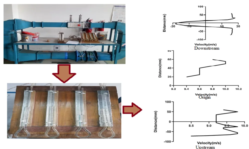
- At various points at the upstream, origin and downstream of the cylinder the flow velocity is measured through pressure difference using manometer at stationary position and at two rotational speeds.
- Distance vs velocity graph is plotted using GraphPad.
- The result shows that for rotational speeds the flow at the downstream changes significantly creating a certain amount of impact.
1. Introduction
Magnus effect has a great significance in fluid dynamics. This effect is based on the rotation of any cylinder. Study of this effect may have great scopes in future. Our plan was to conduct this research to analyze and differentiate between non-rotating cylinder and rotating cylinder with different rotational speeds.
The characteristics of flow is investigated here by using rotating cylinder with two different rotational speeds and non-rotating cylinder. And each scenario was studied under two different flow velocities. In the experiment, eight stations have been taken for determining flow characteristics and velocity profile of the flow [1]. From the experiment, velocity vs distance graph is evaluated by different taping point of the station of cylinder which is in rotation and without rotation state. If the cylinder is in stationary condition, then flow velocity in the upper and lower surface of the cylinder remain same but at the origin of the cylinder in the upstream becomes zero. In the upstream where the origin of the cylinder situated, pressure is high but the upper and lower body of the cylinder pressure is low and velocity is high and symmetric [2]. For rotating cylinder, there are two rotational speeds. And for each speed, pressure is also high in the upstream of the cylinder at origin. In the upper and lower body of the rotating cylinder velocity profile and magnitude is not symmetric. In the upper body velocity magnitude is higher than the lower body in the rotating cylinder [3]. But pressure is lower in the upper body than the lower body in the rotating cylinder [4, 5]. In the downstream pressure decreases and turns to negative pressure in the middle where cylinder actually situated. In the cylinder flow separation is higher than the cylinder and for this reason wake region is higher in cylinder. Velocity profile in the upstream away from the origin, upper and lower surface of the cylinder becomes symmetric [6]. But in the surface of the test section velocity drops significantly because of boundary layer. For the rotational condition, the more the speed and flow velocity, the more pressure difference is noticed at the downstream.
As cylinder is a bluff body, enough wake is created in the downstream region of the cylinder. That’s why, velocity profile in the downstream becomes opposite to actual flow in the upstream. In the right side of the cylinder which is downstream, flow is symmetric in the upper and lower side of the cylinder but in the mid-section cylinder velocity direction and magnitude changes. Here in the mid-section flow velocity fluctuates significantly and direction changes as opposite to the free stream velocity direction [7, 8]. As there is a large wake region created for flow separation, flow velocity magnitude and direction alters [9].
Experimental study of flow field on circular cylinder with semi-circular grooved has been investigated in the following articles. Using linear structural theory, Nakano et al. [10] investigated the flow field and tonal noise over the airfoil. Garni et al. [11] studied the control of flow of airfoil using experimental as well as numerical approach. Gordon [12], through the numerical calculations investigated viscous flow fields by employing cylinder. Croockewit et al. [13] applied an experimental study to identify the longitudinal diffusion in liquid flow through an annulus between a stationary outer cylinder and a rotating inner cylinder. In another work, Peng et al. [14] studied and extended flow around and through a permeable circular cylinder. Krishna et al. [15] performed an experimental study of Characterization of flow through the intake valve of a single cylinder engine using particle image velocimetry. Escudier et al. [16] investigated effects of inner cylinder rotation on laminar flow of a Newtonian fluid through an eccentric annulus. Collins et al. [17] conducted an experimental approach on flow past an impulsively started circular cylinder. Kim et al [18] employed Pressure drop through anisotropic porous medium like cylinder bundles in turbulent flow regime. Khalifa et al [19] studied regimes of flow through cylinder arrays subject to steady pressure gradients. Roshko et al. [20] studied flow forces on a cylinder near a wall or near another cylinder. Hellou et al. [21] investigated cellular stokes flow induced by rotation of a cylinder in a closed channel. Bourguet et al. [22] investigated flow-induced vibrations of a rotating cylinder.
In the light of the experiment, we can say that the change of velocity of a certain region is our main interest and further research on this topic may open a new door for futuristic solutions. Our work is very much relevant to power related problems which can be overcome by studying and controlling Magnus effect.
This manuscript contains the full details of our experimental setup, the data we collected and our final output from this study.
2. Experimental setup
2.1. Identifications of tubes in a yaw meter
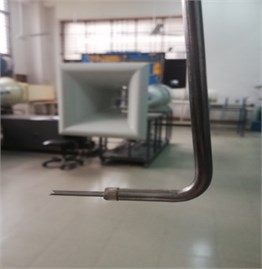
Yaw meter consists of three tubes. The middle one gives the total head measurement (P1) whereas between the other two, one is cut from the upper side and the other one is cut from the lower side. So that the flows come from the upper side of the object is measured by the attached upper tube of the center tube (P2) and the flows which come from the lower portion is measured by the lower side tube (P3). Providing the air flow through the tubes by mouth, there creates some bubbles at the end of the tubes as the tubes are attached with water. Thus, the middle one which gives the value of the total pressure head is denoted as P1 and the side tubes are denoted as P2 and P3, applying the same procedure. It should be checked that while identifying the tubes by giving blow with mouth there should be no suction. Otherwise, there will be a blockage of water in the tubes and the result might be error during the processes.
Fig. 1Three tube probe yaw meter setup
2.1.1. Calibration of yaw meter
Yaw meter was constructed employing three conventional needles of syringe with 1.2 mm diameter. The needles were attached with a stainless steel rod of 6 mm diameter. Each needle is connected with a tube of 1.5 mm diameter which is passed through the rod and can be linked to the manometer. The middle of three tube measures the total pressure which is denoted by P1. Other two tube is denoted by P2 and P3 by which flow angle is measured.
A special facility was established to calibrate the yaw meter with the recent facility. For calibration of the yaw meter, it is aligned horizontally with the direction of flow in the test section. Then the yaw meter is rotated with 5 degrees’ increment both clockwise and anti-clockwise direction. This same procedure is done within 20 degrees.
Table 1Yaw meter calibration table
P1 | P2 | P3 | clockwise | anticlockwise | ||
0 | 0 | 14.2 | 9 | 27 | 0.34 | 0.34 |
5 | 0.088 | 11.75 | 10.5 | 26.5 | 0.08 | 0.6 |
10 | 0.1763 | 9.25 | 12.25 | 26.75 | –0.1875 | 0.87 |
15 | 0.268 | 6.5 | 14.5 | 26.5 | –0.5 | 1.1825 |
20 | 0.364 | 3 | 16.75 | 25.25 | –0.89 | 1.57 |
25 | 0.466 | 0.75 | 18.5 | 22 | –1.43 | 2.11 |
30 | 0.577 | –0.25 | 19.5 | 18.5 | –2.11 | 2.79 |
Fig. 2Calibration of yaw meter
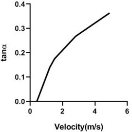
From the calibration, the equation what we get .
That can be written as .
Here, 0.04 and 0.022 as it is compared to the equation of .
2.2. Inclined manometer set up
Sometimes there is a common scene that the diameter of the pipes is smaller so that it is difficult to be fitted with the tube of the inclined U-tube manometer. By using the PLUS, the pipe can be loosened to adjust with the tubes. Sometimes there is a common scene that the diameter of the pipes is smaller so that it is difficult to be fitted with the tube of the inclined U-tube manometer. By using the PLUS, the pipe can be loosened to adjust with the tubes. For low levels of deflections, manometers are used to measure pressure of fluids. Traditional variants include single tube, multi tube, U-tube, vertical, inverted, inclined ones, etc.
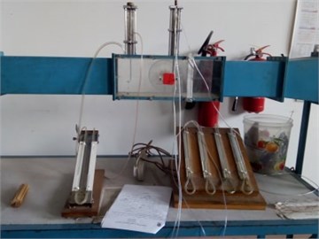
The most popular use for manometer is probably measuring static and total pressure of fluid. To conduct the experiment four U-tube manometers are required as yaw meter has three probes and for the static pressure value. So, four U-tube manometers were set up on a wooden box using glass tube, pipe fittings, measuring scales etc. Wooden blocks were used to keep the manometers inclined at different angles.
Fig. 3Inclined manometer
2.3. Increased diameter of the pipe
Sometimes there is a common scene that the diameter of the pipes is smaller so that it is difficult to be fitted with the tube of the inclined U-tube manometer. By using the PLUS, the pipe can be loosened to adjust with the tubes. Sometimes there is a common scene that the diameter of the pipes is smaller so that it is difficult to be fitted with the tube of the inclined U-tube manometer. By using the PLUS, the pipe can be loosened to adjust with the tubes.
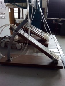
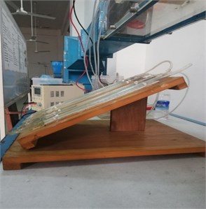
2.3.1. Test section setup
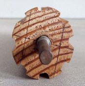
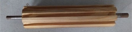
In the test section, there are only two tubes which go through the test section. One is for the upstream flow which is fixed along horizontally but can be moved along vertically. The other one which is kept for the downstream can be moved both horizontally and vertically. The test section should be closed as much as it is possible. There are a sliding open portion at the upper part of the test section which should be closed by using small glasses. Maybe a binding tape can be used to fix those movable part. Wholly the section is very important as cylinder is mounted here and flow separation and other properties can also be seen in this section. Cylinder is employed which has 1 mm semi-circular groove in every 2 mm interval.
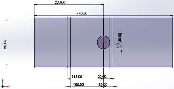
Fig. 4Test section setup, a) dimension of test section and b), c) circular cylinder with semicircular grooved
a)
b)
c)
2.3.2. Motor setup
For rotating a cylinder, a high speed DC motor is needed. A motor is mounted to a cylinder with bearings and screws. It is set up in that way so that it is attached with the test section. Most of the motors which have a good speed have much weight but it should be prior in concern that the weight should be sustainable. Otherwise, the glass of the front part of the test section would not be able to carry out. In the experiment, the speed of the RPM of the motor is up to 2500 rpm by providing 4.5 volts. The rotation of the motor is measured by using the tachometer.
2.3.3. Power source setup
In a power source there are two wires (one is for positive and other is for negative) and a plug for attaching the multi-plug. After connecting the wires with the existing wires of the motor and the plug, the voltage of the power source is increased gradually up to 4.5 volts.
Taco meter is used to determine motor rpm and it was 2100 per minute. Motor is attached to the cylinder shaft. Bearing is set to the test section so that cylinder can rotate easily and less effect of vibration.
2.3.4. Flow controller setup
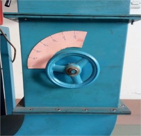
In the current closed loop wind tunnel the test area was appended with a dc engine (pivoting speed more than 2000 rpm). To control the stream rate in a particular piece of air stream a controller was introduced. An inner cutting edge is connected with the controller inside the air stream which controls the stream rate with variety in point of pivot. Association between two electric engines and the air stream was set up for giving high force consistent stream.
Here, in closed looped wind tunnel free stream flow velocity which is provided in upstream was 16.75 m/s. Mass flow rate is controlled by rotating the nob. Two free stream velocity used for this experiment. One velocity is taken 16 m/s when nob is in 90° position which means flow is not affected by the internal blade. Other velocity is taken 8 m/s when nod is in 45° position which means internal blade blocks 50 % mass flow of its original mass flow.
Fig. 5Flow controller nob
3. Experimental method
Chamber is set in the test area. Test segment is square in size which width and stature is 150 mm yet length is 440 mm. As chamber is set at root of the test segment, its upper and lower length from the divider is 75 mm. Chamber distance across is 40 mm. Seven station is taken for the estimation. Two station is taken in the upstream and four stations in downstream. One station is taken in the middle section which is known as origin. Two upstream stations are 80 mm and 100 mm left from the source. Four downstream stations are 20 mm, 40 mm, 60 mm and 80 mm right from the beginning. Yaw meter is associated with the manometer by the line. Four container of yaw meter is associated with the manometer. At the point when inward sharp edge is in 90° condition mass rate is most extreme. For greatest mass stream rate free stream speed is 16 m/s. With the expectation of complimentary stream speed 16 m/s, absolute pressing factor and nearby pressing factor is estimated by the manometric stature. For each station from base to top 17 focuses is taken to quantify the absolute neighborhood pressure. By this stream speed bearing is determined. Stream speed is estimated by this condition:
At that point dc power supply is associated with the engine. DC power supply voltage is taken 4.5 V. At 4.5 V dc engine turns by 2100 rpm. Nearby pressing factor and complete pressing factor is estimated by this condition. By the nearby pressing factor and all-out pressing factor tallness, stream speed size and course is distinguished. Another free stream speed taken when nob is in 45° position. At the point when nob is in 45°, mass stream in air stream diminishes half to unique mass stream rate. Mass stream rate diminishes on the grounds that the stream regulator is in the 45° position. Free stream speed gets 8 m/s for this situation of stream regulator. Aggregate and nearby pressing factor of liquid is estimated in same condition as free stream speed 16 m/s. Speed is estimated at a similar route as past. At that point same cycle is finished deciding pressing factor and speed when chamber is in turn.
4. Experimental results
Two Reynolds number is considered for two distinctive free stream speeds. In a specific free stream speed, stream attributes are dictated by pivoting and without rotating cylinder. In the upstream speed stays steady as their stream is not hindered by the item. Be that as it may, there is some impact on the stream speed of rotating cylinder. As yaw meter yaw meter drawing nearer towards the origin (cylinder), stream speed vacillates significantly for turning chamber. Chamber is turning towards the stream bearing. That is the reason stream speed increments in the upper segment however diminishes in the lower divide. As stream speed expands, pressure diminishes in the upper bit. In lower parcel stream speed lessens and therefore pressure rises.
4.1. Downstream
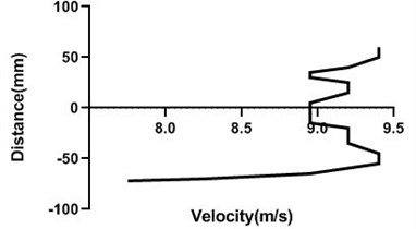
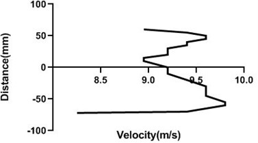
4.1.1. Free stream velocity (9 m/s) with rotation (3.5 V)
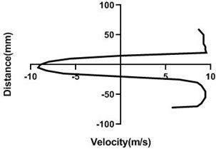
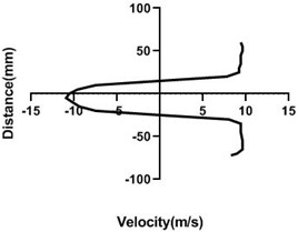
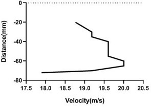
Figs. 6(a-d) illustrates the alteration of flow velocity with the changes of the particular station of the test section. Overall, velocity in the upper portion of the cylinder increases as well as lower portion reduces the most if the station is very near to the body. In the downstream, as the gradual rise in the horizontal direction of the station, upper and lower portion of the velocity becomes congruent which is vividly noticed in Fig. 6(d). For Fig. 6(a) and 6(b) differential pressure is mostly observed where in the bottom section pressure is higher than the upper section. Afterwards, in the Fig. 6(d), differential pressure falls down considerably.
Fig. 6Velocity profile over the rotating cylinder (9 m/s) on downstream at 3.5 V, a) 20 mm, b) 40 mm, c) 60 mm and d) 80 mm
a)
b)
c)
d)
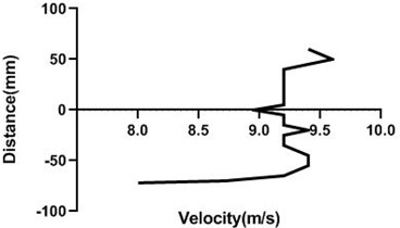
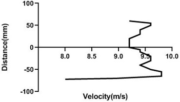
4.1.2. Free stream velocity (9 m/s) with rotation (5.5 V)
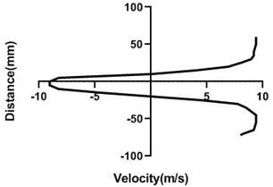
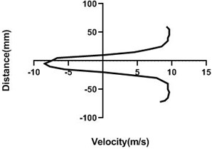
Velocity profile is dependent on the rotational speed of the motor. If a motor rotates in a good speed, then the upper portion of the cylinder velocity will be much greater than the lower portion as pressure is higher in the lower portion. In Fig. 7 motor velocity is > Fig. 1. As a result, differential pressure is higher in the Fig. 7(a-c) but at the last station Fig. 7(d), up and bottom portion of cylinder velocity is analogous to each other. For both portion velocity reduces significantly for the presence of the wall.
There is a flow separation and wake region creates behind the cylinder. That’s why negative pressure happens. This negative pressure originates negative velocity. Yaw meter first height is 80 mm and then its height decreases by 10 mm. In wall flow velocity is lowest for the positive velocity of the upper portion of the downstream cylinder.
Fig. 7Velocity profile over the rotating cylinder (9 m/s) on downstream at 5.5 V, a) 20 mm, b) 40 mm, c) 60 mm and d) 80 mm
a)
b)
c)
d)
4.1.3. Free stream velocity (9 m/s) without rotation
In stationary condition of the cylinder, upper and the lower section of the velocity remains constant as here flow of the wind tunnel is not affected by external force. Hence, in the upper part and lower part flow velocity is also congruent. In wall, flow velocity greatly affected as there pressure greatly escalates and speed of the flow decreases dramatically.
Fig. 8Velocity profile over the non-rotating cylinder (9 m/s) on downstream, a) 20 mm, b) 40 mm, c) 60 mm and d) 80 mm
a)
b)
c)
d)
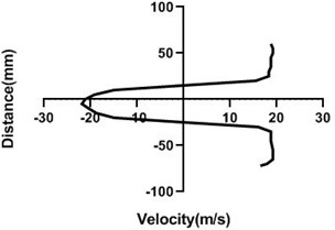
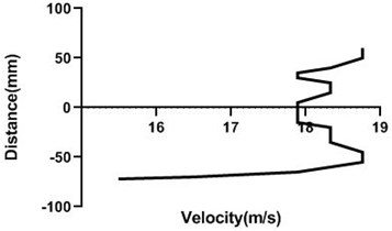
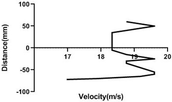
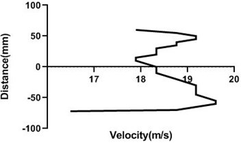
4.1.4. Free stream velocity (18 m/s) with rotation (3.5 V)
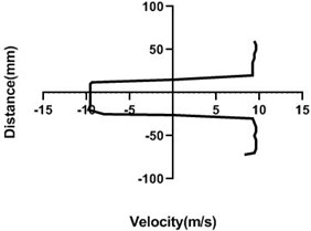
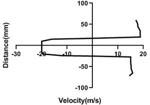
Mass flow rate is highest (18 m/s) in Fig. 9, for the closed loop wind tunnel since flow controller nob is in the 0° angle condition. Hence, flow in the upper part > lower part whereas pressure in the upper part < lower part. Velocity difference is approximately 7 m/s greater in Fig. 9(a). Differential velocity is much lesser in the figure d than the Fig. 9(c). For all station speed falls down considerably in the wall because of the boundary layer theory. As wake region establishes behind the cylinder, velocity direction alters significantly and with the gradual increase of the horizontal direction, wake area reduces and stretches.
Fig. 9Velocity profile over the rotating cylinder (18 m/s) on downstream at 3.5 V, a) 20 mm, b) 40 mm, c) 60 mm and d) 80 mm
a)
b)
c)
d)
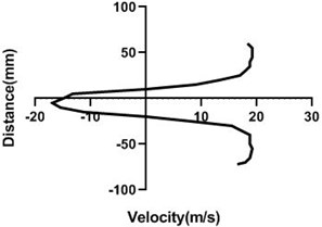
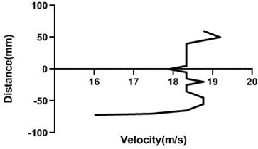
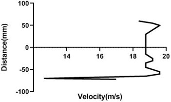
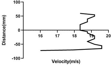
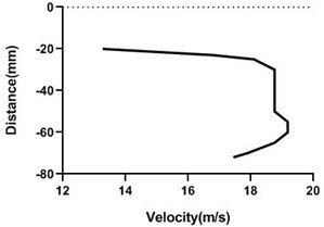
4.1.5. Free stream velocity (18 m/s) with rotation (5.5 V)
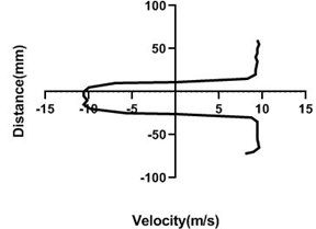
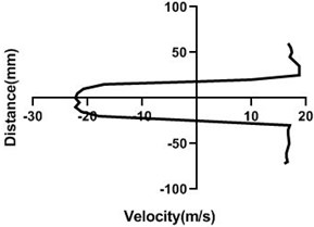
With the increment of the motor speed, wake region turns into thinner and falls down. In comparison with the Fig. 9, wake area stretches with the advancement of the horizontal distance of the test section. For figure c and d, opposite direction is > Fig. 4(c and d). As the motor speed is greater, upper section flow speed is considerably higher than the lower section for Fig. 10(a) and 10(b).
4.1.6. Free stream velocity (18m/s) without rotation
Flow velocity here is not influenced by any other means and therefore up as well as bottom velocity is about analogous. On the other hand, wake area is highest in the Fig. 11(a) and lowest in Fig. 11(d) as here station is in the 80 mm distance from the cylinder. In wall, flow speed reduction is highest in Fig. 11(d).
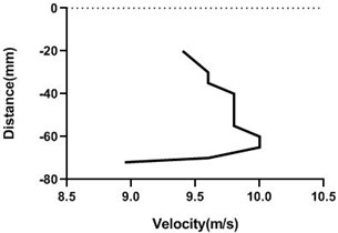
4.2. Upstream
4.2.1. Free stream velocity (9 m/s and 18 m/s) with rotation (3.5 V)
In the upstream, flow velocity profile remains constant but in the wall, velocity reduces. However, if the cylinder is the rotating condition, flow speed is greatly influenced. Infront of the rotating cylinder station, flow field alters most and with the advancement of the horizontal displacement, flow field turns turbulent to laminar. Wall velocity is minimum for the upper side and lower side of the bluff body. Velocity fluctuation is quite low for the Fig. 12(c) and (d) as here mass flow rate is considerably high as well as cylinder is rotating relatively low speed. In the wall, flow speed is lowest for all the station in the upstream.
Fig. 10Velocity profile over the rotating cylinder (18 m/s) on downstream at 5.5 V, a) 20 mm, b) 40 mm, c) 60 mm and d) 80 mm
a)
b)
c)
d)
Fig. 11Velocity profile over the non-rotating cylinder (18 m/s) on downstream, a) 20 mm, b) 40 mm, c) 60 mm and d) 80 mm
a)
b)
c)
d)
Fig. 12Velocity profile over the rotating cylinder on upstream at 3.5 V, a) 80 mm and b) 100mm at 9m/s; c) 80 mm and d) 100 mm at 18 m/s
a)
b)
c)
d)
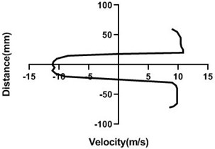
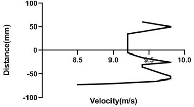
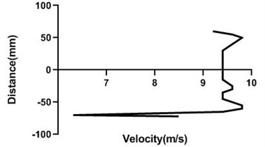
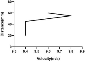
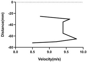
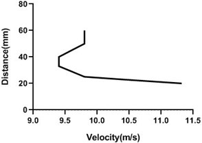
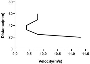
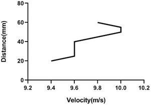
4.2.2. Free stream velocity (9 m/s and 18 m/s) with rotation (5.5 V)
Motor speed is higher than the previous speed and that’s why velocity profile fluctuates a lot. Here, in the Fig. 13(a) and (b), velocity changes from approximately 9 to 9.4 m/s for 80 mm yaw meter condition. As 80 mm yaw meter horizontal position station is very close to cylinder, velocity alters a lot. However, in the 100 mm position of the yaw meter velocity does not change too much.
Fig. 13Velocity profile over the rotating cylinder on upstream at 5.5 V, a) 80 mm and b) 100 mm at 9 m/s; c) 80 mm and d) 100 mm at 18 m/s
a)
b)
c)
d)
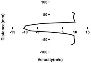
4.2.3. Free stream velocity (9 m/s and 18 m/s) without rotation
Fig. 14(a) and (b) velocity profile do not fluctuate much as the cylinder is in the stationary condition. Therefore, in the upstream of the cylinder flow velocity does not alter significantly. For every station in upstream flow velocity remains constant.
Fig. 14Velocity profile over the non-rotating cylinder on upstream, a) 80 mm and b) 100 mm at 9 m/s; c) 80 mm and d) 100 mm
a)
b)
c)
d)
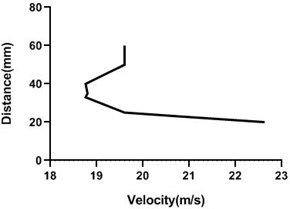
4.3. Origin
4.3.1. Free stream velocity (9 m/s and 18 m/s) with rotation (3.5 V)
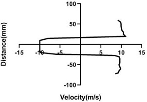
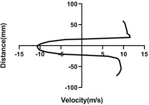
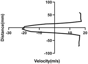
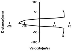
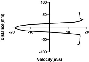
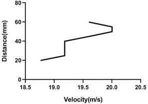
Free stream velocity is 9 m/s. Here nob of the closed loop wind-tunnel is the 45 degree. So, flow velocity is here half of the maximum free stream velocity. Maximum free stream velocity is 18 m/s. As cylinder is not rotating, flow velocity is not affected. As the cylinder is rotating along the flow direction, the velocity of the upper portion of the cylinder increases but lower portion of the cylinder decreases. In lower portion of cylinder Fig. 15(b) and (d) velocity decreases because cylinder motion direction is opposite to the flow direction. Therefore, velocity decreases but pressure increases. In the upper portion Fig. 15(a) and (c), velocity escalates while pressure reduces significantly.
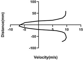
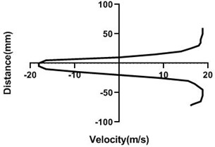
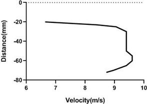
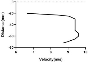
4.3.2. Free stream velocity (9 m/s and 18 m/s) with rotation (5.5 V)
With the increment of the motor speed, free stream flow velocity varies a lot by changing the upper and lower portion flow velocity. Upper section of the velocity escalates, however, bottom section falls down. Hence, pressure in the bottom side of the origin is > top portion of the cylinder. Yet, in wall flow velocity is lowest for all condition.
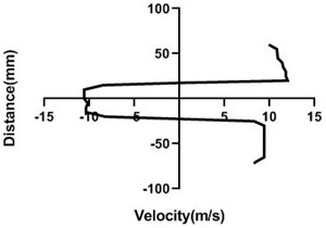
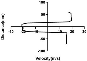
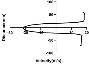
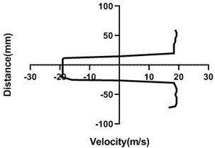
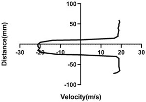
4.3.3. Free stream velocity (9 m/s and 18 m/s) without rotation
Overall, flow velocity in the upper portion and lower portion of the cylinder slightly reduces uniformly but in the perpendicular direction of the yaw meter, flow escalates. Here in 20 mm in Fig. 17(c) and –20 mm in Fig. 17(d) flow velocity is analogous. Yet, in the wall flow alteration is highest. In Fig. 17(a) wall velocity is > Fig. 17(b).
Fig. 15Velocity profile over the rotating cylinder on origin at 3.5 V, a) upper part and b) lower part at 9 m/s; c) upper part and d) lower part at 18 m/s
a)
b)
c)
d)
Fig. 16Velocity profile over the rotating cylinder on origin at 5.5 V, a) upper part and b) lower part at 9 m/s; c) upper part and d) lower part at 18 m/s
a)
b)
c)
d)
5. Discussions
In this experiment two Reynolds numbers have been considered which indicates two free stream velocities. The cylinder has been given two rotational speeds using two different voltages in the motor that helped to rotate the cylinder.
Fig. 17Velocity profile over non-rotating cylinder on origin, a) upper part and b) lower part at 9 m/s; c) upper part and d) lower part at 18 m/s
a)
b)
c)
d)
In stationary position, the cylinder shows an unchanged characteristic at the upstream, an abrupt change at the origin and at the downstream the change is also non-significant. At the upstream velocity remains constant as flow is not obstructed by the object. At the origin the flow is obstructed by the object itself and at the upper and lower portion of the object the change of velocity at different points is abrupt. At the downstream the change of flow characteristics is also non-significant as the cylinder is stationary. At the downstream the flow is hindered at the mid portion due to the presence of the object itself and at different points we get similar characteristics that can be seen from the graphs. And the velocity at the upper and lower portion of the cylinder is almost symmetrical. This changes are applicable for both of the flow velocities. For the lesser flow velocity i.e. 9 m/s the change of velocity is less and for the greater flow velocity i.e. 18 m/s the change of velocity is also greater.
In rotary condition, we have two different rotating speeds that have been achieved by applying two different voltages on the motor that has been used to revolve the cylinder. For both the rotary condition, there is no noticeable change at the upstream. Here also velocity remains constant as flow is not obstructed by the object. At the origin the flow at the upper portion and lower portion shows a significant change. Here the cylinder rotates clockwise and the flow passes in the direction of the cylinder’s rotational motion. So at the origin the flow velocity at the upper portion increases and at the lower portion it is decreased. And at the mid portion the flow is hindered by the object itself.
At downstream the flow velocity changes noticeably. At different points of the downstream the flow velocity at the upper and lower portion of the cylinder changes differently due to flow direction. At the upper portion it increases and at the lower portion it decreases. And at the mid portion it is obstructed by the object itself. So the overall velocity profile at the downstream is as such that the upper and lower portion of the cylinder is not symmetrical. This is applicable for both the rotating speeds. Now for two different flow velocities the scenarios are different. For the greater flow velocity, the change at the downstream at the upper portion of the cylinder is greater and for the lesser flow velocity the change is lesser.
In all scenarios and studying all conditions it has been found that the flow velocity at the upstream is always constant irrespective of the cylinder’s motion as it is not obstructed by the object. There is a minor change or no change at all in the velocity at the origin and at the downstream when the cylinder is stationary. Basically, the changes turn up when the cylinder has rotating motions. And the changes are mainly noticed at the origin and at the downstream and that too at various points on the upper portion of the object where flow velocity is affected by the direction of motion of the cylinder. Unlike the upstream that shows no significant changes, changes at the origin and downstream is major. This significant changes along all the scenarios are shown in the characteristics graphs.
6. Conclusions
This present study observes the change of flow property over a non-rotating cylinder and a rotating cylinder with different rotational speeds. Cylinder is a bluff body and when it is placed in a wind tunnel and air flows over the cylinder with a certain speed that creates a velocity profile over the object and that is the main topic of interest of this study. Here two conditions are considered. First one is when the cylinder is stationary and the second one is when the cylinder is rotating at different rpms. Moreover, some definitive conclusions drawn from the study are mentioned as follows:
1) When the cylinder is stationary the velocity of the air does not change at the upstream because the flow is not hindered by any object. So, the velocity profile is like a straight line. This also applies for the rotational speed of the cylinder when velocity is measured at distant points from the cylinder. Even though the cylinder has a rotational speed, the airflow is not hindered by the cylinder at points far from the object. So, the velocity profile at distant points at upstream for both cases share a noticeable similarity. As velocity does not change at those points at the upstream, pressure does not change either.
2) But when velocity is measured at points closer to the object, in the first case velocity profile remains same as earlier points because the cylinder is stationary. But in the second case, when the cylinder has a rotational speed, the velocity profile changes drastically at closer points. This happens because at points closer to the cylinder the rotational speed of the cylinder affects the flow velocity of air. This effect is not applicable at distant points.
3) The cylinder itself has been fixed as the origin that is midpoint for the whole experimental setup. When velocity at the origin has been measured, the case is not the same. Because at upstream at any certain point velocities can be measured from up to down to get a complete velocity profile as there is no object in the way of airflow. But when the velocity is measured at the origin, it is possible to measure velocity at only the upper and lower portion of the object because mid portion is the object itself. Now when considering two cases that is with and without rotation, velocity profile at both upper portion and lower portion of the origin remains a straight line when the cylinder is stationary. And velocity at the mid portion is zero because airflow is obstructed by the cylinder. And for this, pressure at upper portion and lower portion does not change noticeably and at mid portion it can be considered null. Considering the latter case, the cylinder has a rotational speed. In this case, velocity profile at the upper portion changes. Velocity increases at the upper portion of the cylinder as the rotational speed of the bluff body along with the speed of the airflow affects the flow at the upper portion eventually. So, the velocity profile turns out to be a slightly incremental graph. As velocity increases, pressure decreases here. At the lower portion velocity decreases and pressure increases. At the mid portion it is the same as stationary condition because the flow is hindered by the object which leaves the pressure to be null as well.
4) Velocity profile at the downstream of the cylinder however changes significantly compared to the profile at both the upstream and the origin. For the first situation, when the cylinder is stationary the velocity for the upper portion and lower portion of the cylinder at the downstream remains identical. At the mid portion the airflow is hindered by the cylinder but shows no certain pattern for the change in flow velocity rather changes abruptly. At the upper portion and lower portion pressure remains same while at the mid portion change in pressure is abrupt. Now for the second situation, when the cylinder has a certain amount of rotational speed the velocity at the upper portion of the cylinder at the downstream increases along with the decrement in pressure. While at the lower portion of the cylinder velocity decreases and for this pressure rises. For the mid portion situations are the same for both conditions that is showing abrupt changes in velocity.
5) Two rotational speeds have been used in this experiment. From the comparison of these two speeds it has been noticed that the higher the speed, the more velocity change is noticed at different points at the upper portion of the cylinder and at the downstream.
6) This study observes that for the rotational speed of a bluff body there is a significant amount of change in velocity and pressure at the downstream of that object. This change creates a certain consequence which leaves a great scope for futuristic solutions for renewable energy usage.
7) This study also proves that the change of velocity and pressure at the downstream of the cylinder is more significant when the airspeed is more. The greater the flow velocity, the more the impact observed.
References
-
Parnaudeau P., Carlier J., Heitz D., Lamballais E. Experimental and numerical studies of the flow over a circular cylinder at Reynolds number 3900. Physics of Fluids, Vol. 20, Issue 8, 2008, p. 85-101.
-
Kim J., Choi H. Distributed forcing of flow over a circular cylinder. Physics of Fluids, Vol. 17, Issue 3, 2005, p. 151-744.
-
Drummond J. E., Tahir M. I. Laminar viscous flow through regular arrays of parallel solid cylinders. International Journal of Multiphase Flow, Vol. 10, Issue 5, 1984, p. 515-540.
-
Wheatcraft S. W., Winterberg F. Steady state flow passing through a cylinder of permeability different from the surrounding medium. Water Resources Research, Vol. 21, Issue 12, 1985, p. 1923-1929.
-
Rutgers R. Longitudinal mixing of granular material flowing through a rotating cylinder: part I. descriptive and theoretical. Chemical Engineering Science, Vol. 20, Issue 12, 1965, p. 1079-1087.
-
Yamane K., Nakagawa M., Altobelli S. A., Tanaka T., Tsuji Y. Steady particulate flows in a horizontal rotating cylinder. Physics of Fluids, Vol. 10, Issue 6, 1998, p. 1419-1427.
-
Sanjay M., Kumar B. Flow past a rotating cylinder. Journal of Fluid Mechanics, Vol. 476, 2003, p. 303-334.
-
Selimefendigil F., Öztop H. F. Effect of a rotating cylinder in forced convection of ferrofluid over a backward facing step. International Journal of Heat and Mass Transfer, Vol. 71, 2014, p. 142-148.
-
Nakano T., Fujisawa N., Oguma Y., Takagi Y., Lee S. Experimental study on flow and noise characteristics of NACA0018 airfoil. Journal of Wind Engineering and Industrial Aerodynamics, Vol. 95, Issue 7, 2007, p. 511-531.
-
Al-Garni A. Z., Al-Garni A. M., Ahmed S. A., Sahin A. Z. Flow control for an airfoil with leading-edge rotation: an experimental study. Journal of Aircraft, Vol. 37, Issue 4, 2000, p. 617-622.
-
Gordon D. Numerical calculations on viscous flow fields through cylinder arrays. Computers and Fluids, Vol. 6, Issue 1, 1978, p. 1-13.
-
Croockewit P., Honig C. C., Kramers H. Longitudinal diffusion in liquid flow through an annulus between a stationary outer cylinder and a rotating inner cylinder. Chemical Engineering Science, Vol. 4, Issue 3, 1955, p. 111-118.
-
Yu P., Zeng Y., Lee T. S., Chen X. B., Low H. T. Steady flow around and through a permeable circular cylinder. Computers and Fluids, Vol. 42, Issue 1, 2011, p. 1-12.
-
Murali K. B., Mallikarjuna J. M. Characterization of flow through the intake valve of a single cylinder engine using particle image velocimetry. Journal of Applied Fluid Mechanics, Vol. 3, Issue 2, 2010, p. 23-32.
-
Escudier M. P., Gouldson I. W., Oliveira P. J., Pinho F. T. Effects of inner cylinder rotation on laminar flow of a Newtonian fluid through an eccentric annulus. International Journal of Heat and Fluid Flow, Vol. 21, Issue 1, 2000, p. 92-103.
-
Collins W. M., Dennis S. C. R. Flow past an impulsively started circular cylinder. Journal of Fluid Mechanics, Vol. 60, Issue 1, 1973, p. 105-127.
-
Kim T., Lu T. J. Pressure drop through anisotropic porous mediumlike cylinder bundles in turbulent flow regime. Journal of Fluids Engineering, Vol. 130, Issue 10, 2008, p. 104501.
-
Khalifa Z., Pocher L., Tilton N. Regimes of flow through cylinder arrays subject to steady pressure gradients. International Journal of Heat and Mass Transfer, Vol. 159, 2020, p. 120072.
-
Roshko A., Steinolfson A., Chattoorgoon V. Flow forces on a cylinder near a wall or near another cylinder. Proceedings of the 2nd US Nation Conference on Wind Engineering Research, Fort Collins, 1975.
-
Hellou M., Coutanceau M. Cellular Stokes flow induced by rotation of a cylinder in a closed channel. Journal of Fluid Mechanics, Vol. 236, 1992, p. 557-577.
-
Bourguet R., Jacono D. L. Flow-induced vibrations of a rotating cylinder. Toulouse Institute of Fluid Mechanics, 2014.
-
Klopfenstein R. Jr Air velocity and flow measurement using a Pitot tube. ISA Transactions, Vol. 37, Issue 4, 1998, p. 257-263.
About this article

