Abstract
This paper adopted an indirect mixed method (computational fluid dynamics + boundary element method) based on computational fluid dynamics + Lighthill acoustic analogy theories to compute the flow field and flow-induced noise of the centrifugal pump, and experimentally verified the correctness of computational results. The pressure distribution of the centrifugal pump through an unsteady computation showed that there were obvious separation vortexes at the outlet of the centrifugal pump and pressure at the edge of impellers was obviously more than that of other parts. There were many peak noises on the sound pressure level curve at the outlet of the centrifugal pump. The sound pressure level gradually decreased with the increased frequency. However, sound pressure levels will be a stable value when the analyzed frequency was more than 3000 Hz. Sound pressures at the inlet and outlet of the centrifugal pump were relatively large. Sound pressures at the inlet pipeline gradually decreased from outside to inside and sound pressures of outlet pipeline gradually decreased from inside to outside. The structure of the centrifugal pump was not completely symmetrical, and the sound field was not symmetrical. In addition, the radiation noises in the external field at the inlet and outlet of the centrifugal pump were similar to the radiation of many point sound sources. Peak values of flow-induced noises at the outlet of the centrifugal pump were more than those at the inlet of the centrifugal pump under the working condition of different rotational speeds and flow rates. In the meanwhile, sound pressure levels at the inlet and outlet of the centrifugal pump did not show many differences in amplitudes when the rotational speed was small. When the rotational speed reached up to 3000 r/min, the sound pressure at inlet was more than that at outlet within 1500 Hz-4500 Hz. At many peak frequency points, peak noises at outlet were obviously more than those at inlet, which thus proved that fluid caused large pressure fluctuations due to the interaction between impellers and volutes after flowing through the centrifugal pump and flow-induced noises caused by pressure fluctuations were mainly reflected in blade frequency. The change of the rotational speed and flow rate would not only increase the flow-induced noise in the centrifugal pump, but also seriously affect the external radiation sound field of the centrifugal pump.
1. Introduction
Centrifugal pumps are widely used in industry, agriculture and daily life. Under the current environmental requirements of energy conservation, emission reduction and reduction in radiation noises, high loads, high efficiency and low noise have a high requirement on the design of centrifugal pumps. Namely, centrifugal pumps have to consider its fluid dynamics performance and acoustic performance. Volutes of the centrifugal pump have a special three-dimensional structure. The interaction between impellers and volute tongues causes a strong unsteady flow, which directly affects the performance, vibration and noise characteristics of the centrifugal pump. In practical engineering, the centrifugal pump is usually connected with all kinds of inlet and outlet pipelines. The noise caused by the unsteady effect of impellers and volute tongues will spread outward along connecting pipelines. From the perspective of noise control, it is necessary to consider two aspects, namely noise source and propagation path. On one hand, the direct and effective method of reducing the noise of the centrifugal pump can be searched through starting from the noise source of the centrifugal pump, optimizing impeller design, matching the impeller with volutes, reasonably organizing the internal flow field of the centrifugal pump, weakening the intensity of unsteady effect and reducing separation and strong vortex mixing. On the other hand, the intensity of noise radiation can also be reduced effectively by means of noise elimination. However, the installation of mufflers is restricted by many factors including pipeline structures, operating environment and so on. Therefore, system interference and restriction are removed usually through studying the noise characteristics of the centrifugal pump which is taken as a sound source.
Aiming at the internal unsteady flow field and noise characteristics of the centrifugal pump, a large number of scholars conducted a lot of researches and analysis on this kind of problems through theoretical analysis, experimental research, numerical simulation and so on [1-7]. Langthjem [8, 9] conducted a numerical computation for the flow field and sound field of a two-dimensional centrifugal pump. Results showed that unsteady forces on the blade surface were the main reason for the noise in the centrifugal pump. Geng [10] conducted a numerical simulation and research on the unsteady flow field in the centrifugal pump with and without long and short blades. When flow rate and pump head were similar, impellers with the structure of long and short blades had an opposite effect on pressure fluctuations at the inlet and outlet of the centrifugal pump, compared with the impeller without the structure of short blades. Though long blades were the same in form, short blades of different physical dimensions exerted different influences on the form and amplitude of pressure fluctuations at the inlet and outlet of the centrifugal pump. Ye [11] adopted near-field sound pressure method to conduct experimental research on the noise characteristics of the centrifugal pump on the open-type experimental table, obtained the change rule and frequency characteristics of the centrifugal pump noise with net positive suction head in the case of variable flow rate and constant flow rate, and analyzed the impact of flow rate and the suction of air at the suction inlet on noise and sound pressure levels under different frequencies. Results showed that the sound pressure level of the centrifugal pump increased with the increased flow rate and reached the peak value in the high efficiency area in the case of variable flow rate. Dong [12] conducted a numerical computation and experimental research on the characteristics of external field noises induced by the fluid in the centrifugal pump. In the case of typical flow rate, Reynolds-average method was adopted to obtain the dipole source of wall and FEM/AML method was used to solve the flow-induced noise caused by the interaction between impellers and the dipole source of shell. Si [13] set up a test platform for the flow-induced noise of the centrifugal pump, adopted the acoustic test model of four-pole grid method, experimentally studied the change rule of performance and flow-induced noises of the centrifugal pump with flow rate, and analyzed the characteristics of flow-induced noises in the case of cavitation. In reference [14], this paper reported an experimental investigation of large-scale flow field instabilities in a pump rotor and the process of noise generation by these instabilities. Measurements of the fluctuating components of velocity and surface pressures were made with hot-wire probes and surface mounted pressure transducers on a seven bladed back swept centrifugal water pump impeller operating with air as the working fluid.
This paper adopted an indirect mixed method (computational fluid dynamics+boundary element method) to compute the flow field and flow-induced noise of the centrifugal pump, and experimentally verified the correctness of computational results and systematically studied the change of flow-induced noises at the inlet and outlet of the centrifugal pump with flow rate and rotational speed.
2. Theoretical basis for solving sound field
N-S equation is the basic governing equation which described the instantaneous flow state of flow field in the centrifugal pump:
wherein, represents viscous stress tensor. The equation set also describes the sound source of flow and its propagation phenomenon. However, there are still many difficulties in directly conducting acoustic numerical simulation at present. This paper adopted an indirect mixed method based on CFD + Lighthill acoustic analogy theories. From the computational results of flow field obtained by means of CFD to the process of acoustic computation, the determination of sound source parameters was the key to solving the problem. The foundation of acoustic analogy theories was Lighthill sound field general equation derived by N-S equation:
wherein, is Lighthill stress tensor; is Kronecker function; is the variable quantity of fluid density. When there is fixed hard boundary in flow field, free space Green’s function could be used to obtain the far-field solution of equation. According to FW-H theories, the most common equation form of Lighthill acoustic analogy could be established as follows:
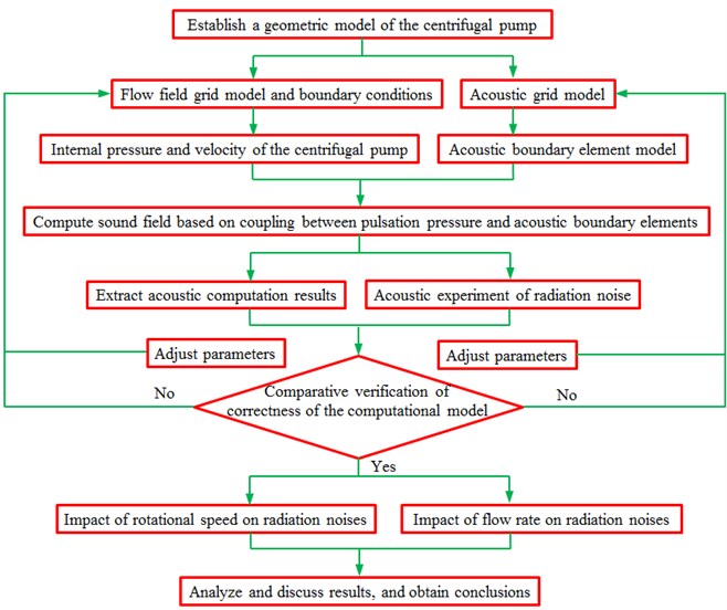
wherein, is solid boundary function; refers to the variable quantity of fluid pressures. The first item of the right formula stands for stress source, namely quadrupole source, and existed in turbulent vortexes. The second item is the noise caused by the oscillation of rigid body which the fluctuation pressure of fluid acted on. Namely, force source distributed on solid surface is a dipole source, like unsteady force due to the interference between blade surface and turbulence on the internal surface of centrifugal pump. The third item refers to the distributed source of surface caused by volume fluctuation in fluid medium, namely monopole source. Three kinds of sound sources existed in the internal flow field of the centrifugal pump. How to determine effective sound source in flow field was an important issue. For a well-designed centrifugal pump, volutes and blade surface could be deemed as rigid, on which dipole source was widely distributed. The fluid medium of the centrifugal pump was considered as incompressible. Its volume fluctuation was nearly 0. Monopole source could be neglected. The radiation efficiencies of quadrupole and dipole sources were in direct proportion to the 6th power and 3rd power of Mach number, respectively. Usually, Mach number of the centrifugal pump was far less than 0.1. Therefore, quadrupole source noise could also be neglected. The noise source caused by the internal flow of volutes of the centrifugal pump was a dipole source. The computation of flow field was conducted in commercial software FLUENT. Pressure data acting on the inner wall of volutes in the computational results of flow field was extracted to be interpolated into acoustic model. Then, ACTRAN was used to simulate the flow-induced noise of the centrifugal pump. In order to make this study clearer, we have added a flow chart for the whole process, as shown in Fig. 1.
Fig. 1Flow chart for the whole process
3. Numerical computation for the flow field of the centrifugal pump
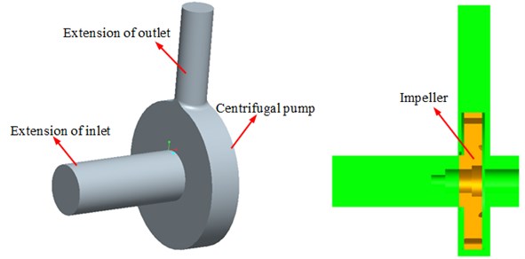
Before three-dimensional numerical simulation was conducted for the internal flow field of the centrifugal pump, it was necessary to conduct a three-dimensional solid modeling for the flow field firstly, generate the grids of the established model and finally import it into commercial software FLUENT to conduct numerical computation. The flow passage components of the centrifugal pump mainly contained four parts, namely inlet, impellers, volutes and outlet. The computed flow rate of the centrifugal pump was 60 m3/h. For the accuracy of computation and the stability of flow at the flow passage of inlet and outlet, a flow field model of the centrifugal pump was established. In addition, a pipeline model connecting with the centrifugal pump was established respectively at the inlet and outlet, as shown in Fig. 2.
Fig. 2Geometric model of the centrifugal pump
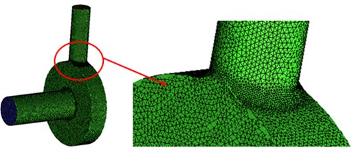
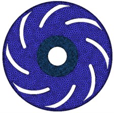
Grid generation is an important factor of numerical simulation. The quality of grids has a direct impact on the accuracy of computational results. With the in-depth application of CFD in practical engineering design, geometric shapes and flow fields have become increasingly complex. As the first part of the whole computation and analysis process, grids also become increasingly difficult. Grids can be usually divided into structured grids and unstructured grids according to the distribution of their nodes in space. Structured grids are a kind of grids with regular topology structure, whose advantage is simple storage and high computational efficiency and disadvantage is a heavy workload in the case of generating grids with complex-shape objects. Unstructured grids are randomly distributed in space. Without any structural characteristics, unstructured grids are very suitable to deal with complex boundary problems and complete the self-adaption of grids. According to the structural characteristics of hydraulic machinery, the blade surface of the centrifugal pump is a hook face with warped space. This paper adopted well-adapted unstructured grids. Grids of the model were generated in GAMBIT. The number of grids in every region is as follows: The impeller contained 701.306 grids; volutes had 626.038 grids; inlet included 102.198 grids; outlet contained 92.355 grids. Finally, the grid model for the flow field of the centrifugal pump was shown in Fig. 3. Numerical computation of the flow field is with the help of commercial software FLUENT. In computation, water was selected as the medium and considered as incompressible. In addition, the viscosity coefficient of water was a constant value. The boundary conditions of inlet and outlet were velocity inlet and pressure outlet. The grid interfaces between inlet pipeline and impellers and between impellers and volutes were defined. In the case of computation, steady computation was firstly conducted to obtain the initial result of stable flow field. Then, unsteady computation was conducted on this basis. In the case of steady computation, turbulence model selected - two-equation model; near the wall, standard wall function was adopted; SIMPLE algorithm was used to solve the governing equation of flow field; grids in the impeller region adopted a multiple reference frame model; the number of iterations was 3000; residual error was less than 10-5. Unsteady computation adopted large eddy simulation method. Sub-grid model selected Smagorinsky Lilly model. Mobile grids were selected in the impeller region. Sliding grid technique was applied to the data transfer of inlet pipeline and volute. The time step of unsteady computation was 5.75×10⁻⁵s. In each time step, the impeller rotated about 1°. Computation was completed after the number of iterations reached 20. Due to the complexity of structure and in consideration of computational cost and time, grid generation of this computation adopted unstructured grids and grid encryption was conducted at the inlet and outlet of the centrifugal pump, static and dynamic interface and casting tongue.
Fig. 3Computational grids of centrifugal pump
a)
b)
Fig. 4 presented steady computational results for the flow field of the centrifugal pump. Fig. 5 presented unsteady computational results for the flow field of the centrifugal pump. It could be seen that there were obvious differences between steady and unsteady results. For the pressure distribution of the centrifugal pump in unsteady computation, outlet pipeline had obvious separation vortexes. In addition, pressures at the edge of impellers were obviously more than that of other parts mainly because flow velocity became large under the action of rotational forces of impellers and large pressure was thus caused.
Fig. 4Steady computational results for the flow field of the centrifugal pump
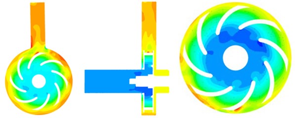
a) Pressure distribution
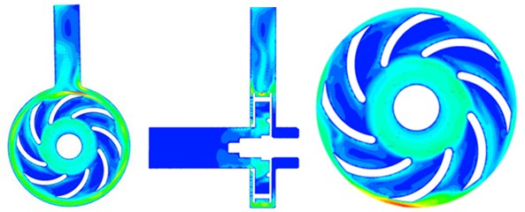
b) Velocity distribution
Fig. 5Unsteady computational results for the flow field of the centrifugal pump
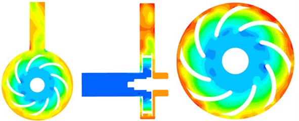
a) Pressure distribution
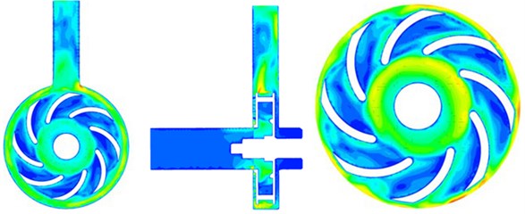
b) Velocity distribution
4. Numerical computation and experimental verification for the flow-induced noise
4.1. Numerical computation for the flow-induced noise
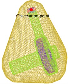
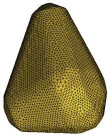
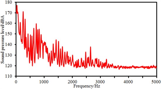
Flow field was the foundation of computing the sound field of the centrifugal pump. Therefore, the computed pressure fluctuation of the centrifugal pump was imported into ACTRAN. Acoustic boundary element grids and field point grids were established based on the geometric model of the centrifugal pump, as shown in Fig. 6. The acoustic computational model contained 7.089 elements and 7.590 nodes. In ACTRAN, the pressure fluctuation of the centrifugal pump was mapped to acoustic grids. In this way, acoustic grids could obtain all the flow field information of the centrifugal pump and realize acoustic-vibration coupling. Computed frequency was 5000 Hz and step size was 20 Hz. Sound pressure levels at the outlet of the centrifugal pump was extracted, as shown in Fig. 7. From the figure, it could be noticed that there were many peak noises on the sound pressure level at the outlet of the centrifugal pump. The overall change trend decreased gradually with the increased frequency. However, sound pressure levels will be a stable value when the analyzed frequency was more than 3000 Hz. The reason is that when the fluid passed through the centrifugal pump, the flow-induced noise under the blade frequency, harmonic frequency and axial frequency would be increased due to effects of impeller rotation. When the analyzed frequency was low, flow-induced noises generated by pressure pulsations were mainly manifested on blade frequency, harmonic frequency and axial frequency due to effects of rotation of the centrifugal pump impeller. The axial frequency was /60 = 33.3 Hz ( is rotational speed of the centrifugal pump). When the analyzed frequency was more than 3000 Hz, effects of the axial frequency could be neglected, while effects of blade frequency and harmonic frequency were also obviously reduced. Therefore, sound pressure levels in high frequency bands were relatively stable.
Fig. 6Acoustic computational model of the centrifugal pump
a)
b)
Fig. 7Sound pressure levels at the outlet of the centrifugal pump
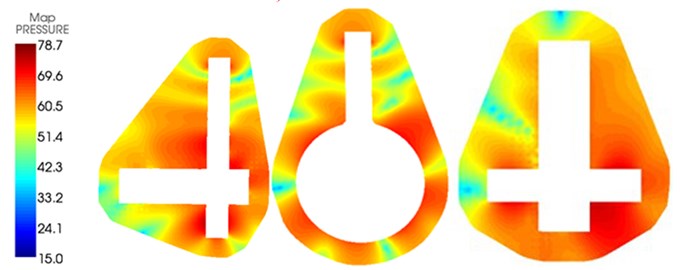
The sound pressure distribution of the centrifugal pump at 800 Hz was extracted, as shown in Fig. 8. As displayed from the figure, sound pressures at inlet pipeline and outlet pipeline in the centrifugal pump was relatively large. Sound pressures at inlet pipeline gradually decreased from outside to inside mainly because noises at the inlet pipeline of the centrifugal pump was caused by the flow fluid. At this time, impellers of the centrifugal pump did not have any effect on it. The flow velocity of fluid at the inlet pipeline would decrease with the increased flow distance and cause small radiation noises. Sound pressures at the outermost side of the outlet pipeline were the minimum. Sound pressures close to the impeller center was the maximum mainly because the impeller would strengthen its flow function on fluid. The volute structure of the centrifugal pump was completely symmetrical, but the impeller of the centrifugal pump was not symmetrical, as shown in Fig. 2. The flow field was mainly caused by the impeller. Therefore, the radiated noise will be from the impeller, and was transmitted to the volute to cause the vibration of the volute. Finally, the noise will be transmitted to the environment. Therefore, the sound field of the centrifugal pump was not symmetrical. In addition, the radiation noise of external field produced at the inlet and outlet pipelines of the centrifugal pump was similar to the radiation of multiple point sound sources.
Fig. 8Internal and external sound field distributions of the centrifugal pump
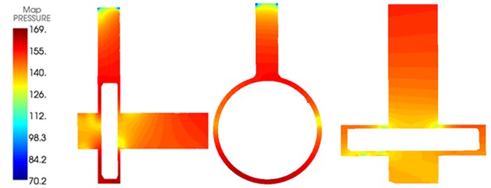
a) Internal sound field
b) External sound field
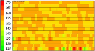
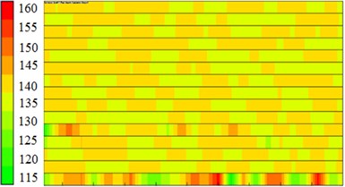
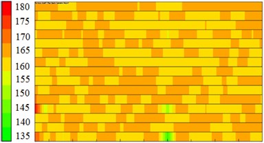
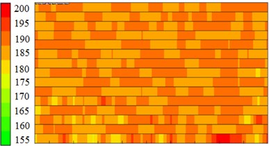
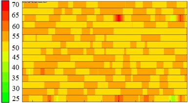
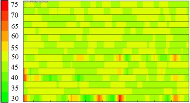
When the acoustic response of the centrifugal pump was computed in ACTRAN, the acoustic panel contribution of the centrifugal pump was also computed. The boundary element grid of the centrifugal pump was divided into 14 panels according to the proximity of structures so as to compute the acoustic contribution of every panel to observation points, as shown in Fig. 9. 6 observation points were arranged in and out of the centrifugal pump and located at the inlet, outlet, impeller center, edge of impellers and in the front and rear of volutes. Observation points at the inlet, outlet, impeller center and edge of impellers were used to observe the contribution of acoustic panels to the internal sound field of the centrifugal pump. Observation points in the front and rear of volutes were used to observe the contribution of acoustic panels to the external sound field of the centrifugal pump. It could be seen from the figure that the acoustic contribution of each panel to 6 observation points was not obviously different. Panels making great contributions to acoustic response could not be obtained through acoustic panel technology.
Fig. 9Contribution of acoustic panels to the sound field of the centrifugal pump
a) Inlet
b) Outlet
c) Impeller center
d) Edge of impellers
e) In the front of volutes
f) In the rear of volutes
4.2. Experimental verification for the flow-induced noise of the centrifugal pump
The numerical computation model of flow-induced noises of the centrifugal pump was very complicated, and its correctness of related results should be verified by experimental test. Experimental table of the flow-induced noise of the centrifugal pump was an open-type system, of which the layout was shown in Fig. 10. In order to guarantee consistency with numerical simulation conditions, experimental flow rate was 60 m3/h, and the rotational speed was 2000 r/min. Water in the suction sump 2 of the centrifugal pump was inhaled into pipeline 6 and flew through outlet pipeline 9 and water tank 10. To compare numerically computational results with experimental results, a sound pressure sensor 7 was arranged at the outlet pipeline of the centrifugal pump to test flow-induced noises. The 8103 hydrophone of Danish B&K Company was used as the sound sensor. The hydrophone has a small size and high sensitivity, within the measurement scope of 0.1 Hz-180 kHz. The Pulse 3050 and 3160 portable modules from Danish B&K were used as the data recorder. The experimental environment was very quiet. Therefore, it was not necessary to consider the impact of background noises on experimental noises. Each test was conducted three times. The average value of three experimental results was taken as the final result.
Based on computational fluid dynamics and acoustic boundary elements, simulation computation could be conducted on flow-induced noises caused by pressure pulsations which were generated from rotation of the centrifugal pump. Computational results were compared with experimental results, as shown in Fig. 11.
Fig. 10Test of the experimental flow-induced noise of the centrifugal pump: 1 – centrifugal pump; 2 – suction sump; 3 – coupler; 4 – torque tachometer; 5 – electromotor; 6 – inlet pipeline; 7 – sound pressure sensors; 8 – data acquisition system; 9 – outlet pipeline; 10 – water tank
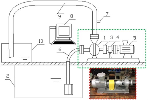
Fig. 11Comparison between experiment and simulation of flow-induced noises at the outlet
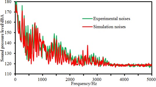
Changing trends of the numerical simulation and the experimental testing were basically consistent. The fluid in the flow channel was affected by rotation of the impeller and then generated periodic pressure pulsations, so that high sound pressure levels were generated under the blade frequency, harmonic frequency and axial frequency. Within 3000 Hz, there are many major peak frequencies, including blade frequency, harmonic frequency and axial frequency, etc. After 3000 Hz, the sound pressure level did not present very outstanding peak values, where it was basically kept at a fixed value. A lot of peak values also existed in experimental results, where the peak frequency was kept consistent with that in the numerical simulation, and only the peak amplitudes presented very tiny differences. Main contribution frequencies of flow-induced noises could be corresponding to both the simulation and experiment results, so accuracy of simulation and experiment was verified mutually. In addition, peaks of experimental test were basically more than numerical simulation results, so full consistency could not be ensured. The reason is that besides blade frequency, harmonic frequency and axial frequency, peak frequencies of experimental values also involved a series of natural frequencies caused by fluid-solid coupling effects of the whole pipeline system, which could not be avoided in the experimental test. However, numerical simulation could not take into account effects of the whole pipeline system. In addition, flow-induced noises belong to an interdiscipline of computational fluid mechanics and aeroacoustics, so mutual calling of models requires some simplification and hypotheses. Despite of the theoretic correctness, the computation results would still be affected to a certain extent.
5. Impact of rotational speed and flow rate on the flow-induced noise of the centrifugal pump
The flow-induced noise of the centrifugal pump was computed when flow rate was 60 m3/h and rotational speed was 2000 r/min. Rotational speed and flow rate were main factors affecting the flow-induced noise of the centrifugal pump. Therefore, the numerical simulation model changed two parameter values respectively to observe the change of flow-induced noises at the inlet and outlet of the centrifugal pump.
5.1. Impact of rotational speed on the flow-induced noise of the centrifugal pump
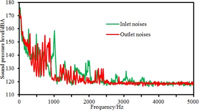
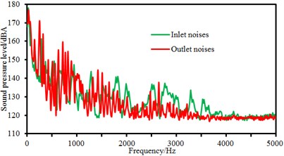
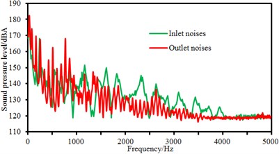
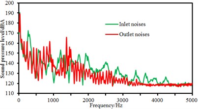
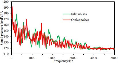
The flow rate 60 m3/h was unchanged, and the rotational speed of the centrifugal pump was changed from 1500 r/min to 3500 r/min. Step size was 500 r/min. Sound pressure levels at the inlet and outlet of the centrifugal pump were compared, as shown in Fig. 12.
Fig. 12Comparison of flow-induced noises at the inlet and outlet under different rotational speeds
a) 1500 r/min
b) 2000 r/min
c) 2500 r/min
d) 3000 r/min
e) 3500 r/min
As displayed from the figure, sound pressure levels at the inlet and outlet of the centrifugal pump did not present many differences in amplitudes. However, it could be obviously seen that the sound pressure level of flow-induced noises at the outlet of the centrifugal pump had more peak values than that at the inlet of the centrifugal pump. It was because the sound pressure level of flow-induced noises under blade frequency components increased due to the rotational impellers when fluid passed through the centrifugal pump. In the meanwhile, sound pressure levels at the inlet and outlet of the centrifugal pump did not present many differences in amplitudes when rotational speed was small. When rotational speed reached up to 3000 r/min, sound pressure levels at the inlet of the centrifugal pump was more than that at the outlet of the centrifugal pump within 1500 Hz to 4500 Hz. It could also be seen that peak noises at the outlet of the centrifugal pump was obviously more than that at the inlet of the centrifugal pump at many peak frequency points. It proved that fluid produced large pressure fluctuation due to the interaction between impellers and volutes after flowing through the centrifugal pump. Flow-induced noises caused by pressure fluctuations were mainly reflected in blade frequency.
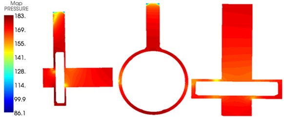
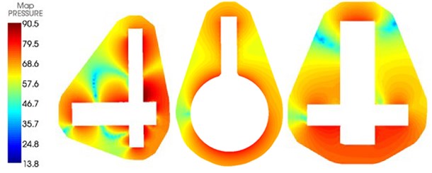
Contours for the internal and external radiation noises of the centrifugal pump at 800 Hz were extracted at the rotation speed of 3000 r/min, as shown in Fig. 13. Through comparing the figure with Fig. 8, it could be seen that the increase of rotational speed would increase flow-induced noises in the centrifugal pump and seriously affect the external radiation sound field of the centrifugal pump. Similarly, flow-induced noises at the outlet pipeline of the centrifugal pump gradually decreased from inside to outside and flow-induced noises at the inlet of the centrifugal pump gradually decreased from outside to inside.
Fig. 13Internal and external sound fields of the centrifugal pump at the rotation speed of 3000 r/min
a) Internal sound field
b) External sound field
5.2. Impact of flow rate on the flow-induced noise of the centrifugal pump
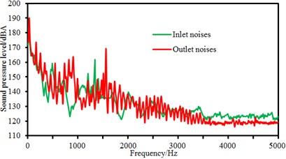
The rotational speed 2000 r/min was unchanged, and flow rate was changed from 60 m3/h to 140 m3/h. Step size was 20 m3/h. Flow-induced noises at the inlet and outlet of the centrifugal pump were computed, as shown in Fig. 14. Flow rates 60 m3/h and 80 m3/h represented small flow rate condition; 120 m3/h and 140 m3/h represented large flow rate condition. Therefore, this paper systematically studied the flow-induced noise at inlet and outlet under different levels of flow rate conditions. As shown in the figure, there were many peak noises at the outlet pipeline of the centrifugal pump in low frequency and many frequency points of peak noises were superposed with those at the inlet of the centrifugal pump, which was similar to the change of sound pressure levels at the inlet and outlet of the centrifugal pump under different rotational speeds. However, it could also be obviously seen that flow-induced noises had many peaks in low frequency. Peaks of flow-induced noises at the outlet of the centrifugal pump was more than that at the inlet of the centrifugal pump, which showed that the internal pressure fluctuation of the centrifugal pump was still main reason for the generation of flow-induced noises after fluid passed through the centrifugal pump. From the comparison of all figures, it could be seen that the flow-induced noise also had the natural frequency of pipeline system; these amplitude frequencies changed little with the change of flow rate; only amplitudes changed with the change of flow rate. When flow rate increased, excitation increased, producing flow-induced noises with high amplitude.
Fig. 14Comparison of flow-induced noises at the inlet and outlet under different flow rates
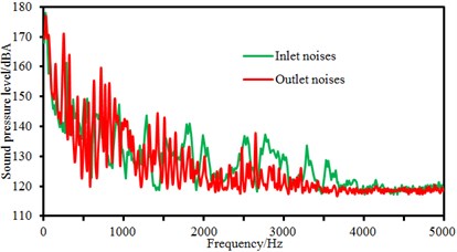
a) 60 m3/h
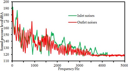
b) 80 m3/h
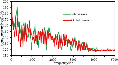
c) 100 m3/h
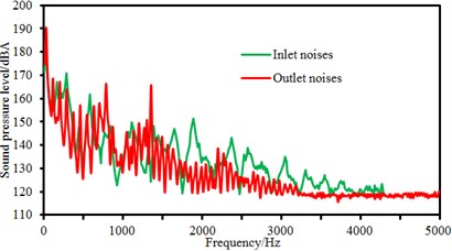
d) 120 m3/h
e) 140 m3/h
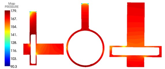
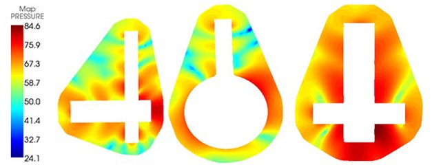
The internal and external sound field distributions of the centrifugal pump under the flow rate of 80 m3/h were extracted, as shown in Fig. 15. Through comparing the figure with Fig. 8, it could be seen that the increase of rotational speed would increase the flow-induced noise in the centrifugal pump and seriously affect the external radiation sound field of the centrifugal pump. In the same way, flow-induced noises at the outlet pipeline of the centrifugal pump gradually decreased from inside to outside and flow-induced noises at the inlet pipeline of the centrifugal pump gradually decreased from outside to inside.
Fig. 15Internal and external sound fields of centrifugal pump under the flow rate of 80 m3/h
a) Internal sound field
b) External sound field
6. Conclusions
This paper adopted an indirect mixed method based on CFD+Lighthill acoustic analogy theories to compute the flow field and flow-induced noise of the centrifugal pump, and experimentally verified the correctness of computational results and reached the following conclusions:
1) The pressure distribution of the centrifugal pump through unsteady computation showed that there were obvious separation vortexes at the outlet of the centrifugal pump and pressures at the edge of impellers were obviously more than that of other parts. There were many peak noises on the sound pressure level at the outlet of the centrifugal pump. The overall change trend gradually decreased with the increased frequency. However, sound pressure levels tended to be a stable value when the analyzed frequency was more than 3000 Hz.
2) Sound pressures at the inlet and outlet pipelines of the centrifugal pump were relatively large. Sound pressures of inlet pipeline gradually decreased from outside to inside and sound pressures of outlet pipeline gradually decreased from inside to outside. The structure of the centrifugal pump was not completely symmetrical, and thus the sound field was not symmetrical. In addition, the radiation noises of external field at the inlet and outlet pipelines of the centrifugal pump were similar to the radiation of many point sound sources. Panels making great contributions to the internal and external sound fields of the centrifugal pump could not be obtained through acoustic panel technology.
3) The flow-induced noise of the centrifugal pump measured by experiments was compared with numerically computational results. Their change trends were basically the same and peak values of experimental flow-induced noises were relatively larger. Numerical simulation model was reliable in the whole analyzed frequency band.
4) Peak values of sound pressure levels of flow-induced noises at the outlet of the centrifugal pump were more than those at the inlet of the centrifugal pump under the working condition of different rotational speeds and flow rates. In the meanwhile, sound pressure levels at the inlet and outlet of the centrifugal pump did not present many differences in amplitudes when the rotational speed was small. When the rotational speed reached up to 3000 r/min, the sound pressure at inlet was more than that at outlet within 1500 Hz to 4500 Hz. At many peak frequency points, peak noises at outlet were obviously more than those at inlet, which thus proved that fluid generated large pressure fluctuations due to the interaction between impellers and volutes after flowing through the centrifugal pump and flow-induced noises caused by pressure fluctuations were mainly reflected in blade frequency.
5) The change of the rotational speed and flow rate would not only increase the flow-induced noise in the centrifugal pump, but also seriously affect the external radiation sound field of the centrifugal pump. The change rule of flow-induced noises at the inlet and outlet pipelines of the centrifugal pump did not change with the change of rotational speed and flow rate.
References
-
Shouqi Y., Qiaorui S., Fei X., et al. Numerical calculation of internal flow-induced noise in centrifugal pump volute. Journal of Drainage and Irrigation Machinery Engineering, Vol. 29, Issue 2, 2011, p. 93-98.
-
Barrio R., Parrondo J., Blanco E. Numerical analysis of the unsteady flow in the near-tongue region in a volute-type centrifugal pump for different operating points. Computers and Fluids, Vol. 39, Issue 5, 2010, p. 859-870.
-
Yuan S., Yang J., Yuan J., et al. Experimental investigation on the flow-induced noise under variable conditions for centrifugal pumps. Chinese Journal of Mechanical Engineering, Vol. 25, Issue 3, 2012, p. 456-462.
-
Minggao T., Yong W., Houlin L., et al. Effects of number of blades on flow induced vibration and noise of centrifugal pumps. Journal of Drainage and Irrigation Machinery Engineering, Vol. 30, Issue 2, 2012, p. 131-135.
-
Wu D., Wang L., Hao Z., et al. Experimental study on hydrodynamic performance of a cavitating centrifugal pump during transient operation. Journal of Mechanical Science and Technology, Vol. 24, Issue 2, 2010, p. 575-582.
-
Li Z., Wu P., Wu D., et al. Experimental and numerical study of transient flow in a centrifugal pump during startup. Journal of Mechanical Science and Technology, Vol. 25, Issue 3, 2011, p. 749-757.
-
Lucius A., Brenner G. Numerical simulation and evaluation of velocity fluctuations during rotating stall of a centrifugal pump. Journal of Fluids Engineering, Vol. 133, 2011, p. 081102.
-
Langthjem M. A., Olhoff N. A numerical study of flow induced noise in a two-dimensional centrifugal pump. Part I: hydrodynamics. Journal of Fluids and Structures, Vol. 19, Issue 3, 2004, p. 349-368.
-
Langthjem M. A., Olhoff N. A numerical study of flow induced noise in a two-dimensional centrifugal pump. Part II: hydroacoustics. Journal of Fluids and Structures, Vol. 19, Issue 3, 2004, p. 369-386.
-
Geng S. J., Nie C. Q., Huang W. G., Feng T., Liu K. Numerical study of unsteady flow in centrifugal pump with different type of impellers. Chinese Journal of Mechanical Engineering, Vol. 42, Issue 5, 2006, p. 27-31.
-
Ye X. M., Pei J. J., Li C. X., Liu Z. Experimental study on noise characteristics of centrifugal pump based on near-field acoustic pressure method. Journal of Chinese Society of Power Engineering, Vol. 33, Issue 5, 2013, p. 375-381.
-
Dong L., Dai C., Kong F. Y., Fu L., Xia B. Flow-induced exterior noise characteristics of a centrifugal pump as a turbine and different noise’ contribution analysis. Journal of Vibration and Shock, Vol. 35, Issue 5, 2016, p. 168-174.
-
Si Q. R., Yuan S. Q., Yuan J. P. Experimental study on influence of impeller-tongue gap on the performance and flow-induced noise characteristics of centrifugal pump. Journal of Vibration and Shock, Vol. 35, Issue 3, 2016, p. 164-169.
-
Choi J. S., Mclaughlin D. K., Thompson D. E. Experiments on the unsteady flow field and noise generation in a centrifugal pump impeller. Journal of Sound and Vibration, Vol. 263, Issue 3, 2003, p. 493-514.
About this article
This work was partially supported by the National Natural Science Foundation of China (Grant No. 51606154), the Natural Science Foundation of Shaanxi Province (Grant No. 2016JQ1019), and the Fundamental Research Funds for the Central Universities of China (Grant No. 15GH0311). The authors would like to acknowledge the computing services from the High Performance Computing Center of Northwestern Polytechnical University.
