Abstract
As the flow structure in the centrifugal pump is complicated, it always causes serious noises, which has become an important problem in environmental protections. Some works have been completed for optimizing and reducing radiated noises of centrifugal pumps, but optimized algorithms are traditional and easily fall into local extreme values, so that final results are not always the optimal. For overcoming disadvantages of traditional algorithms, this paper proposed a novel MLGA-PSO (Multi-layer Genetic Algorithm-Particle Swarm Optimization) algorithm to make an optimization for noises and hydraulic performance of centrifugal pumps. This algorithm starts from the organizational structure of individuals and separates the global search from the local search, which can not only accelerate the convergence speed, but also avoid reducing the global search ability. The algorithm could effectively overcome the contradiction between global search ability and convergence speed. Inlet diameter, impeller blade outlet width, blade outlet angle and amount of blades are as designed variables. In order to verify advantages of the proposed MLGA-PSO algorithm in global search ability, optimizing speed and stability, GA (Genetic Algorithm), PSO (Particle Swarm Optimization) and GA-PSO (Genetic Algorithm-Particle Swarm Optimization) algorithms are chosen to carry out the compared experiment. Results show that the proposed MLGA-PSO algorithm has higher efficiency and accuracy. Finally, total noises of the optimized noise in the near-field and far-field using MLGA-PSO algorithm are 181 dB and 74 dB, respectively. Total noises in the near-field are reduced by 4.7 %, while those in the far-field are reduced by 16.9 %. It is clearly that the optimized centrifugal pump presents an obvious noise reduction effect.
1. Introduction
At present, centrifugal pumps have become a main equipment to be used for energy recovery. It is widely applied in important fields including petrolic and chemical industries [1-4]. As the internal flow structure is complicated, it always causes serious noises during operation, which has become an important problem in environmental protections [5-8]. In the past, researches on hydraulic design of centrifugal pumps mainly focused on performance and cost, but failed to pay enough attention to noise control. As the requirement is higher and the environmental standard is stricter, it is urgent to improve hydraulic performance of centrifugal pumps and reduce their noise levels through optimizing geometric parameters.
Noises of centrifugal pumps include structural vibration-induced noises and fluid-induced noises [9-11]. Structural vibration-induced noises are from structural design and manufacture, and have been solved by active control technologies. Mechanisms of internal fluid-induced noises of centrifugal pumps are more complicated, and are a wide frequency band. Therefore, flow-induced noises have become a studied hot topic. With the centrifugal pump as the studied object, Dong [12] adopted Reynolds Average Navier-Stokes method to obtain dipole sound sources under typical flow rates, applied the FEM/AML method to solve flow noises under dipole sound sources of impellers and shells, and analyzed spectral characteristics of noise sources with different properties. Si [13] established a test table of flow-induced noises of centrifugal pumps, applied the four-end network method to study performance of the centrifugal pump and flow noises and analyzed flow noises with cavitation occurrence. Dong [14] pointed out that the blade outlet angle had impacts on radiated noises. Based on comprehensively considering hydraulic performance and noises, the performance will reach the optimal level when the blade outlet angle was 30°. Minggao [5] kept other geometric parameters of centrifugal pumps and impellers unchanged, and modified the blade numbers to 4, 5, 6 and 7 respectively to study impacts of blade number on flow-induced noises of centrifugal pumps. In order to investigate impacts of impeller outlet width on radiation noises of centrifugal pumps under water power excitation, Liu [15] kept other geometric parameters of centrifugal pumps and impellers unchanged, and applied BEM acoustic-vibration coupling computation and the experimental test method to analyze radiation noises when impeller outlet widths were 8, 10 and 12, respectively. For improving flow-induced noises of centrifugal pumps, Dai [16] established an experimental system to test flow-induced noises. Studied results show that flow-induced noises under different flow rates not only contain characteristic frequencies, but also include a low-frequency broadband spectrum. However, these reported researches only conducted a parametric analysis on flow noises of centrifugal pumps, but did not apply algorithms to optimize flow-induced noises of centrifugal pumps.
Some works have been completed for optimizing flow-induced noises of centrifugal pumps, but the optimized algorithms are traditional and easily fall into local extreme values, so that the final results are not always the optimal. For example, in order to optimize hydraulic and acoustic performance of centrifugal pumps, Dai [17] established a multi-objective optimization method for hydraulic and acoustic performance of centrifugal pumps based on response surfaces. With 4 indexes including sound pressure levels of blade frequency noises, head lift, efficiency and shaft power as the standard, Si [18] adopted the weight matrix method to complete a multi-objective optimization design on the impeller. For improving flow performance of a centrifugal pump with a low specific speed under designed working conditions, Yuan [19] applied an optimization method which combined numerical simulation, experimental design, approximation model and genetic algorithm, and selected 4 parameters as designed variables to obtain an optimal impeller parameter combination.
For overcoming disadvantages of traditional optimization algorithms, this paper combines a novel MLGA-PSO algorithm with numerical simulation technologies to conduct a multi-objective optimization for flow noises and hydraulic performance of the centrifugal pump, where parameters including inlet diameter, impeller blade outlet width, blade outlet angle and amount of blades are as designed variables. Optimized results are compared with those of traditional optimization algorithms. Results show that both the optimized efficiency and accuracy are improved.
2. Numerical computation for flow field of centrifugal pumps
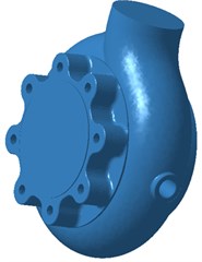
A single-stage and single-suction centrifugal pump was taken as the analyzed model, as shown in Fig. 1. Designed performance parameters of the centrifugal pump: designed flow rate is 130 m3/h; pumping head lift is 25 m; rotating velocity is 2900 r/min; specific speed is 180. Geometric parameters of main flow passage components of the pump: inlet and outlet diameters of the impeller are 225 mm and 340 mm, respectively, blade number is 10, and impeller outlet width is 12 mm, volute base circle diameter is 355 mm, baffle tongue angle is 36°, and volute outlet diameter is 225 mm.
In this paper, the flow passage in the centrifugal pump has a complicated structure. After being exported as a “step” format, the geometric model was then imported into ICEM-CFD software system for defining the boundary and solid. Then, the model could be divided into structural meshes and non-structural meshes using the automatic mesh division function. Compared with non-structural meshes, structural meshes have a simpler structure, quicker generation speed and easier convergence. However, for a geometric model with a complicated structure, hybrid meshes are often used to divide the model as meshes with high quality and applicability could be generated more easily. Therefore, hybrid meshes were selected in the paper and mesh independence analysis was also checked. After generation, the meshes were saved as a “mesh” file used for numerical simulation of the internal flow field. After sliding meshes in each flow domain were completed, the interface was used to connect all the flow domain into a completed flow field meshes. Fine meshes were set in near-wall regions, so that the accuracy of transmitted data could be ensured. In general, computational results are deemed to be unrelated with meshes when the computational error of two sets of meshes is smaller than 2 %. Regarding the model in the paper, three sets of meshes were used for the trial computation. Results are shown in Table 1. Amounts of computational meshes were 5605734, 6709087 and 7500865, respectively. Results show that the computational error was less than 1.94 % when the amount of meshes was more than 7500865. Therefore, the mesh of the computational model was 7500865, namely the maximum size of the centrifugal pump was 4mm which could satisfy requirements of the mesh independence test. Fig. 2 shows meshes of the centrifugal pump in completed and local regions.
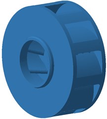
Fig. 1Geometric model of volutes and impellers of centrifugal pumps
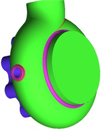
a) Volute
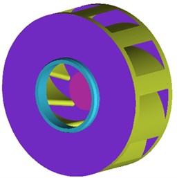
b) Impeller

c) Blade
Table 1Comparison of computational results of three sets of meshes
Mesh scheme | Flow field maximum mesh (mm) | Maximum mesh on surface (mm) | Total amount of meshes | Pressure RMS values (Pa) | Relative change of pressure RMS values |
1 | 30 | 8 | 5605734 | 1990 | |
2 | 26 | 6 | 6709087 | 2091 | 5.05 % |
3 | 22 | 4 | 7500865 | 2132 | 1.94 % |
After the mesh division of this model was completed. Boundary conditions should be set. Mainly the impeller structure will be analyzed, so that boundary definitions of the impeller are considered here. Setting of detailed boundary conditions: impeller inlet boundary is set as a velocity inlet; volute outlet boundary is set as a full development condition of flow; coupling faces of impeller passage regions, impeller volute clearance and volute passage regions are set as interfaces for subsequent processing of dynamic and static areas. Other boundary conditions are set as wall surfaces.
Meshes were imported into CFX-Pre. Fluid medium of different flow domains was set. Water was set as the medium in this paper. Referenced pressures were set as one atmospheric pressure. SST model was adopted as the turbulence model. The turbulence model could more effectively simulate flow separation phenomena in the centrifugal pump and obtain more accurate results. As for the rotary flow domain, the rotational speed was set to be 2900 r/min; axis was set as the rotational axis. Water in the flow passage was a rotating body; water in the volute was a non-rotating body. In steady-state computation, the dynamic-static domain interface was set as a frozen rotor. The inlet was set as a pressure inlet condition; pressure p was 1.10×10⁵Pa. Working conditions were changed through modifying the outlet flow rate, so that the mass outlet was set as the outlet boundary condition. Adiabatic boundary conditions were adopted for solid wall surfaces. The roughness was given to the solid wall surface. Near-wall regions were processed by a standard wall surface functions. High-order solution accuracy was adopted, where the convergence residual error RMS was set to be 10-5, and the amount of computational iteration steps was 1000. In unsteady computation, results of the steady computation were taken as initial values. Boundary conditions were changeless. The dynamic-static domain interface was changed to transient frozen rotor. The computational cycle was 0.33 s. 3.44828×10⁻⁴s was selected as one time step. Stable results of the last cycle were selected to be analyzed.
Fig. 2Completed and local mesh models of centrifugal pumps
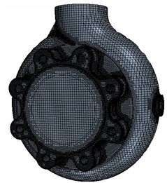
a) Completed meshes
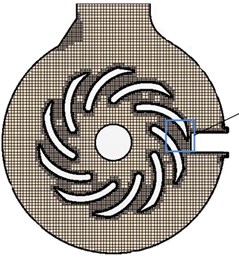
b) Impeller meshes
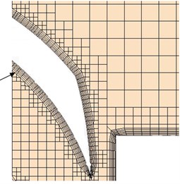
c) Blade meshes
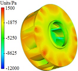
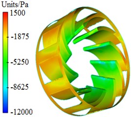
Pressure and velocity distributions of the centrifugal pump were extracted, as shown in Fig. 3 and Fig. 4. It is shown in these figures that pressures and velocities at edges of the impeller are obviously more than those at the center. The reason is that the flow velocity of fluids in centrifugal pumps will be increased under the high-speed impeller, so that serious pressure differences are caused. As well, Rotational velocity in the impeller will cause pressure and velocity fields on the volute surface.
Fig. 3Pressure distribution of centrifugal pumps
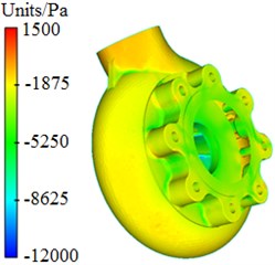
a) Completed structure
b) Impeller
c) Blade
3. Numerical computation and experimental test for the radiation noise
3.1. Numerical computation for the radiation noise of the centrifugal pump
The volute will vibrate because of the high-speed rotation of the fluid in the centrifugal pump, then generate radiated noises. Noises are usually computed by acoustic boundary element method. Acoustic boundary element method can be divided into direct boundary element and indirect boundary element. Direct boundary element is applicable to solving problems inside and outside a curved surface, where the unknown function in an equation is the value of the physical amount to be solved at the boundary. Indirect boundary element is widely applicable to an open, closed or intersected surface. The completed system doesn’t have to be taken into account when the flow field in the centrifugal pump is computed, and the system impedance is large in the experimental test. Therefore, computing acoustic is replaced by completed sound absorption property at the inlet and the outlet. Moreover, as the space of the computational model is not totally-enclosed, indirect boundary element is selected for the computation. Noises of the centrifugal pump were computed by VIRTUAL.LAB software. Firstly, pressure fluctuations on the surface of the output shell and impeller were computed based on URANS unsteady value. Then the sound field was computed based on pressure fluctuations, and the sound field was solved by indirect boundary element.
Fig. 4Velocity distribution of centrifugal pumps
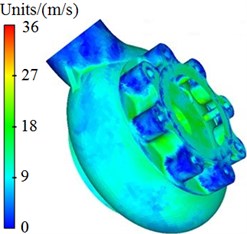
a) Completed structure
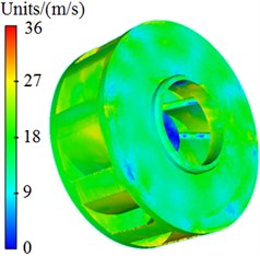
b) Impeller
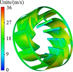
c) Blade
An acoustic boundary element model of the centrifugal pump was established, as shown in Fig. 5. Meshes of a boundary element model should meet the following conditions, i.e., 6 elements are in the minimum wave length, or an element should be more than 1/6 of the wave length of the maximum frequency:
where, is the maximum frequency, is the propagation velocity of sound in the fluid, is the length of the element. In this paper, as the analyzed frequency is 2500 Hz, sound velocity in water is 1500 m/s, then the length of the acoustic mesh must meet the condition 100 mm. Furthermore, meshes should be consistent in size as smaller local meshes cannot improve the computational accuracy. For this reason, structured meshes with the element length of 6 mm were adopted, and the maximum frequency was 41667 Hz, which completely met the computational requirements. Meshes of acoustic boundary element and meshes of the structural finite element were mapped using Element Maximum Distance. 4 proximate nodes in the elements within the distance of 10 mm were selected to carry out interpolation. The excitation of unsteady pressure fluctuations on the shell surface became acoustic boundary conditions through fast Fourier transform. The sound source extracted from fluid computation also existed in the meshes of the fluid model. Therefore, sound source needed to be transferred to the acoustic meshes through data mapping. The inlet and outlet of the model were defined as completed sound absorption property, and other surfaces were assumed as total reflective surfaces, characteristic impedance was 1.5×10⁶kg/(m2·s) and sound velocity was 1500 m/s.
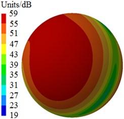
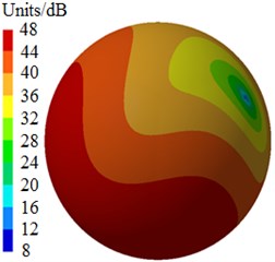
Fig. 6 shows radiated noises of the centrifugal pump in the near field and far field caused by the rotational fluid. It shows that the radiated noise reduces rapidly with the increase of the analyzed frequency less than 1000 Hz. When the analyzed frequency is more than 1000 Hz, the radiated noise will change slightly on the whole. The radiated noise of the centrifugal pump in the near field presented obvious peak values at 400 Hz, 490 Hz, 650 Hz, 900 Hz, 1000 Hz and 1150 Hz, with peak values of 167 dB, 165 dB, 162 dB, 156 dB, 155 dB and 154 dB respectively. The reason why there are so many obvious peak values in the near field is because the fluid in the centrifugal pump will be intensified by blade frequencies, harmonic frequencies and shaft frequencies. Similarly, the radiated noise of the centrifugal pump in the far field had obvious peak values at 200 Hz, 400 Hz, 490 Hz, 650 Hz, 900 Hz and 1150 Hz, with peak values of 78.9 dB, 71.8 dB, 68.8 dB, 64.1 dB, 58.0 dB and 53.4 dB respectively. This shows that most of noise frequency points in near field and far field are overlapped. Some frequency points are different because the radiated noise in the far field is caused by structural resonance. In addition, there is an obvious valley value about 1300 Hz in the near and far field. The radiated noise in the near field is completely induced by the fluid in the centrifugal pump. However, the radiated noise in the far field is caused by fluids and vibrations of volutes. Contours of sound pressures in the near field and far field at 400 Hz, 650 Hz and 1150 Hz were extracted respectively, as shown in Fig. 7 and Fig. 8. According to Fig. 7, with the increase of the analyzed frequency, sound pressures on the impeller reduce obviously. Fig. 8 shows that sound pressures corresponding to the outlet of the centrifugal pump is more than that at other positions.
Fig. 5Acoustic boundary element model of centrifugal pumps
a) Volute model
b) Impeller model
c) Field point model
Fig. 6Radiated noises of centrifugal pumps in the near and far field
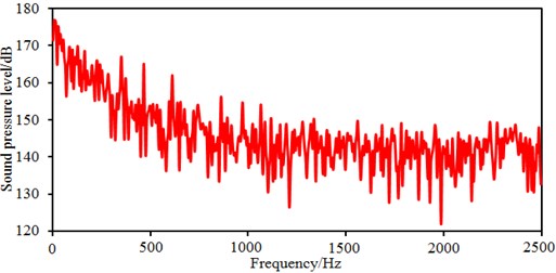
a) Radiated noises in the near field
b) Radiated noises in the far field
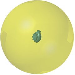
Fig. 7Contours of radiated noises in the near field
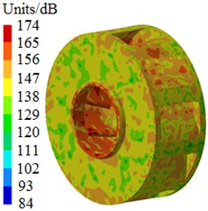
a) 400 Hz
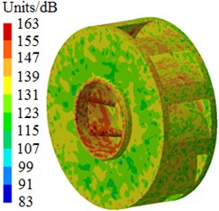
b) 650 Hz
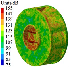
c) 1150 Hz
Fig. 8Contours of radiated noises in the far field
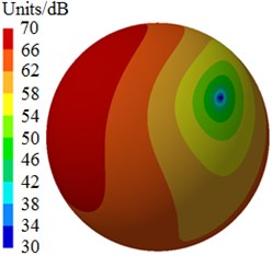
a) 400 Hz
b) 650 Hz
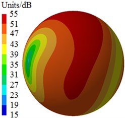
c) 1150 Hz
3.2. Experimental test on the radiated noise of centrifugal pumps
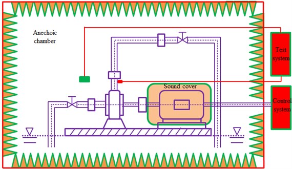
To compute radiated noises of the centrifugal pump in the near and far field, the flow field should be computed before establishing acoustic boundary element model. Moreover, the data should be transmitted and mapped for several times. Therefore, the computational results should be verified. The test system for noises of the centrifugal pump is composed of three major parts, including testing environment, experiment table as well as test and control system, testing and analyzing system, as shown in Fig. 9. According to features of the product and experimental requirements, a semi-anechoic chamber was selected as the testing environment [20-23]. The main structure of the chamber was concrete walls, with the average transmission loss of 40 dB. The walls of the semi-anechoic chamber were made of sound absorption wedges. The acoustical absorption coefficient of the terrazzo floor was less than 0.04. The chamber was ventilated by a forced convection system. The background noise of the testing chamber was less than 25.0 dB, the environmental coefficient was 0.33, and the cut-off frequency was less than 125 Hz. The accuracy error of the free field within 125 Hz-12500 Hz in the space 0.8 m away from the wedge surface complied with the standard. In the noise testing system of the semi-anechoic chamber shown in Fig. 9, the working noise of the centrifugal pump should be tested under pressure, flow, temperature and rotating speed [5, 6]. The experimental table for noise testing includes the centrifugal pump and fixtures for its installation, motor system which could offer needed rotating speed as well as fixtures for its installation, connecting mechanism between the motor and the water pump, tank for storing cooling liquid which can change internal pressure and simulate different pressures and the pressures at the inlet and outlet of the water pump, heating/cooling device of the cooling liquid, pipeline system with flowmeter and flow control valve. In addition, the experimental table should take into account the testing requirements of different centrifugal pumps. The main parts of the noise testing table were designed into interchangeable parts to ensure that the table would be convenient, fast, stable, labor-saving and the control system would be universal. The driven motor of this testing table was arranged in the chamber to drive the pump through a belt. An acoustic shield was designed to shield the noise from the motor, belt pulley, coupling and other transmission devices. The motor fixture and the centrifugal pump fixture were subject to vibration attenuation and sound insulation. Then the background noise would all be over 10 dB less than the operating noise of the centrifugal pump, thus ensuring that the table could meet the requirement for background noises. The noise testing system was measured by B&K sound level meter. The microphone and cables could meet the requirements. The sound level meter collected sound pressure signals of the centrifugal pump at each testing point, and transmitted signals to the computer through sound card in a linear way, and the computer would analyze and dispose the signals on a real-time basis.
Fig. 9Experimental test on radiation noises of the centrifugal pump
During the experimental test, inspectors stood out of the semi-anechoic chamber to operate the test and control system on the experimental table, and to control the centrifugal pump under required rotating speeds, pressures, flow rates and temperatures. The noise of the centrifugal pump was tested according to requirements to obtain background noises and operating noises under each stable rotating speed. The table of the centrifugal pump should be free from interference of vibrations and noises. The tested frequency in the free field at each tested point should be more than 125 Hz. The distance between parts and walls should be more than 1.5 m. The temperature should be between 18 °C and 30 °C, and the relative humidity should be less than 70 %. The test was conducted repeatedly after preparation and requirements were met. Proper sampling frequency should be selected, so that discrete signals obtained from continuous signal sampling can reserve main features of original signals, without any interference or distortion. If the sampling frequency was too high, a lot of discrete data would be extracted from a waveform, and storage space would be large and computational time would be long. In addition, frequency resolution would decrease during Fourier transform for signals. When the sampling frequency is too low, the discrete time-domain signals might not reflect waveform features of original continuous signals, leading to frequency chaos. Nyquist sampling theorem pointed out that the sampling frequency should be higher than 2 times of the maximum signal frequency. In actual application, the sampling frequency was 3-4 times of the useful frequency of signals. This paper only studied noise characteristics within 2500 Hz, so that the sampling frequency was 10000 Hz, sampling time interval was 1×10⁻⁵s and the amount of FFT points was 1000. The experimental site was shown in Fig. 10(a). The measurement point P1 which represented the near field was located 100 mm above the centrifugal pump outlet, while the measurement point P2 which represented the far field was located 1000 mm in front of the centrifugal pump, as shown in Fig. 10(b). The tested results and the numerical simulation were compared, as shown in Fig. 11 and Fig. 12.
The head and efficiency of the centrifugal pump were experimentally extracted while the radiated noise was tested. Fig. 11 presents comparisons of the head and efficiency between the experimental test and numerical simulation. As shown in Fig. 11(a), changing tendencies of the head between the experimental test and numerical simulation were completely consistent, and the head reduced gradually with the increased flow rate. Except for the head loss in the pipes, water also has to face resistance when the centrifugal pump works, which causes the head loss in the centrifugal pump. Such head loss is called as internal loss which is directly proportional to the square of flow rate . Assume the internal resistance of the centrifugal pump is . Then the internal loss of the centrifugal pump will be . When the flow rate of the centrifugal pump is 0, the head will be . When the flow rate of the centrifugal pump is , the head will be . Therefore, the head of the centrifugal pump will reduce with the increased flow rate. The maximum error of the head is 3.6 %. As shown in Fig. 11(b), changing tendencies of efficiency between the experimental test and numerical simulation were completely consistent, and they are both increased when the horizontal coordinate reaches 1. When the working condition is the designed flow rate, the maximum efficiency of the centrifugal pump will be 73.1 %. The maximum error in this efficiency is 1.1 %. This shows that the model for computing the flow field of the centrifugal pump is reliable. However, whether the computation and process for transferring the data from flow field to the acoustic model are reliable needs to be further verified by the noise obtained in the experimental test.
Fig. 10Experimental site and positions of tested points
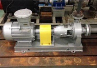
a) Experimental site
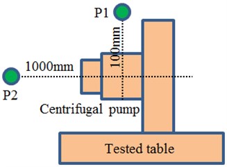
b) Positions of tested points
Fig. 11Comparison of the performance between experiment and simulation
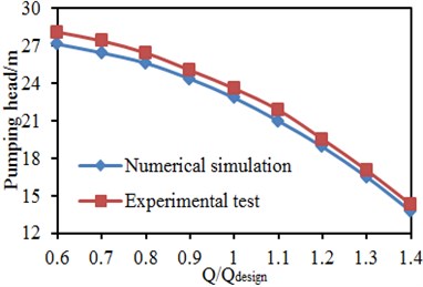
a) Head
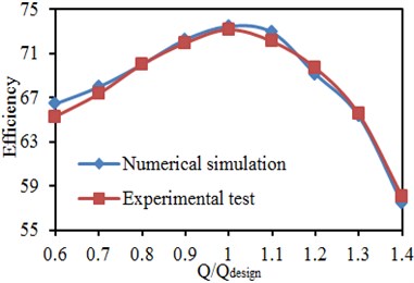
b) Efficiency
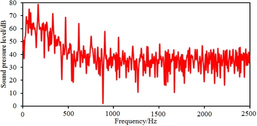
The flow noise caused by pressure fluctuations of centrifugal pumps can be computed based on computational fluid dynamics and acoustic boundary element. Computational results were compared with those of the experimental one, as shown in Fig. 12. Changing tendencies in the numerical simulation and experimental test were consistent on the whole. As affected by rotation of the impeller, the fluid in the flow pass generates periodical pressure fluctuations because of periodical rotation of the impeller, thus causing large sound pressure level at blade frequencies, harmonic frequencies and shaft frequencies. There were several peak frequencies within 2500 Hz, including blade frequencies, harmonic frequencies and shaft frequencies. In the experimental result, there are many peak values at these frequency points, and only amplitudes of these peak values were slightly different. The main frequencies contributing to flow noises were consistent between simulation results and experimental results, which verified the accuracy of the simulation model. In addition, some additional peak values in the experiment were not presented in the numerical simulation. Besides blade frequencies, harmonic frequencies and shaft frequencies, peak frequencies in the experiment include natural frequencies of the system caused by fluid-solid coupling in the loop system, which is unavoidable in the experiment. On the contrary, in the numerical simulation, it’s impossible to take into account the impact of the pipeline of experimental test. In addition, flow noises are an interdiscipline between computational fluid mechanics and aero-acoustics. The models selected from two disciplines should be simplified and assumed. The models which are theoretically correct may affect the computational results. Nevertheless, computing flow noises by numerical simulation is effective, and the numerical model for flow noises can replace the experimental test.
Fig. 12Comparison of radiated noises between experiment and simulation
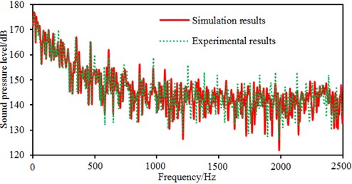
a) Radiated noises in the near field
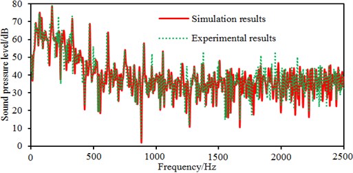
b) Radiated noises in the far field
4. Multi-objective optimization design on the centrifugal pump
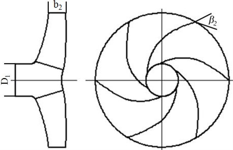
Due to the large flow noise, it is thus necessary to choose an algorithm to optimize the centrifugal pump. However, during the optimization, it also needs to ensure that the performance of the centrifugal pump cannot be reduced. Therefore, the optimization should be a multi-objective in the paper. The lowest internal force loss and the minimum radiation noise of the centrifugal pump were taken as the objective function. Reference [17] has conducted a detailed analysis on parameters which affected internal force loss and noise of a centrifugal pump. Results show that amount of blade , impeller inlet diameter , blade outlet angle and impeller outlet width affect internal force loss and noise of the centrifugal pump most obviously. Therefore, the paper took these parameters as designed variables. Relevant meanings of these parameters are shown in Fig. 13. The computational function of the internal force loss and radiated noise can refer to references [17, 24]:
wherein, is the internal force loss in centrifugal pumps, is the radiated noise of centrifugal pumps, is the amount of blades, is the blade outlet angle, is the inlet diameters of the impeller, is the impeller outlet width, is the designed flow rate, is the designed speed, and is specific speed.
Fig. 13Designed variables in the multi-objective optimization
As an optimization algorithm based on the theory of swarm intelligence, Particle Swarm Optimization (PSO) conducts the optimized search by intelligence from cooperation and competition among particles [25]. It determines the search according to its own speed, remembers the best solution that is shared by all the particles, and has a fast convergence speed. It is used widely, such as in the optimization of nonlinear function, control of voltage stability, training of neural network and other practical problems. Nevertheless, PSO algorithm also has low precision, easy divergence and other shortcomings in the early algorithm. In the case of convergence, particles tend to be homogenized since all the particles fly in the optimal direction, thus obviously slowing down the convergence speed in the later period and easily falling into the local optimum. Genetic algorithm has a good global search ability, which could quickly search out the whole solution in the space without falling into the fast descent trap of the local optimal solution. Besides, by virtue of its intrinsic parallelism, it can easily conduct the distributed computation to speed up the solving process. However, genetic algorithm has poor local search ability, so that the traditional genetic algorithm needs more time to complete the optimization and the search efficiency is relatively low. In practical application, the genetic algorithm is prone to cause premature problems. Therefore, it is the most difficult problem to adopt an algorithm which is necessary to keep fine individuals and maintain the diversity of the group.
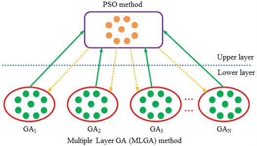
The algorithm in the paper started from the organizational structure of individuals and separated the global search from the local search, which could not only accelerate the convergence speed, but also avoid reducing the global search ability. The algorithm could effectively overcome the contradiction between global search ability and convergence speed, and it was called as MLGA-PSO algorithm. The organizational structure of individuals in MLGA-PSO algorithm was shown in Fig. 14. In the low layer, the algorithm composed of independent subpopulations, was evolved by genetic algorithm to be mainly responsible for the global search. In the low layer, optimal individuals of all subpopulations formed the upper elite population, which applied PSO algorithm for evolution to be mainly responsible for the local search of elite individuals in order to accelerate the convergence speed.
Fig. 14Schematic diagram of structures for individuals in MLGA-PSO algorithm
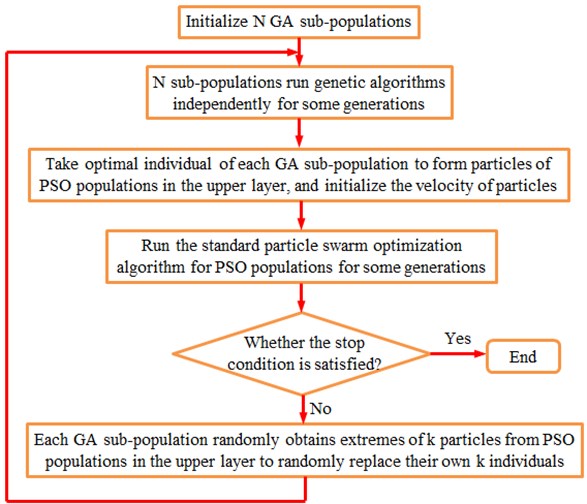
The algorithm randomly initialized subpopulations, recording them as , 1, 2,..., . Each subpopulation operated its own genetic algorithm independently. After some generations, optimal individuals of each subpopulation were taken out to form the elite population, recording as PSO. PSO algorithm was applied to evolve the elite population. After some generations, whether it met the stop criteria should be determined. If satisfied, the results could be output. Otherwise, each GA subpopulation randomly obtained individual extremes of particles from the upper elite population to randomly replace their own individuals. At this point, the first round of MLGA-PSO algorithm was completed and GA subpopulations started the genetic algorithm again and looped until the stop criteria were met. MLGA-PSO algorithm has the flow chart as shown in Fig. 15.
Fig. 15Flow chart of MLGA-PSO algorithm
Compared with other genetic algorithms and particle swarm optimization algorithms, MLGA-PSO algorithm takes genetic algorithm as the main structure to ensure the global search ability. It further chooses multi-subpopulation structures to better maintain the diversity of the population and benefit the global search, which is very suitable for the parallel computing. Besides, it applies PSO algorithm to search elite individuals locally, which can speed up the convergence. Moreover, it uses multi-layer structures to effectively separate individuals which are responsible for the global search from the upper individuals that conduct the local search. This could not only accelerate the optimized speed, but also avoid reducing global search ability. There are mature GA and PSO modules in the commercial software ISIGHT. The MLGA-PSO algorithm proposed in this paper could be achieved by compiling a simple sub-program. In this algorithm, the computational formula proposed by Eq. (2) is taken as the optimized objective. Then, operations such as finite element modeling and result extraction could be conducted according to designed variables through calling ANSYS and VIRTUAL.LAB software in ISIGHT software, so that the multi-objective optimization of the centrifugal pump could be achieved. ANSYS software is compiled based on APDL language, so that all operations could be completed through writing APDL script commands in the sub-program. Therefore, parameterized modeling and data extraction could be achieved. The compiled script document is submitted to ANSYS: script language equipped in ANSYS calls the ANSYS kernel to execute script commands; a cgns input document is generated and submitted to an analyzer. Then, VIRTUAL.LAB is called to compute noises and generate a result document.
In order to verify advantages of MLGA-PSO algorithm in the global search ability, optimizing speed and stability, GA, PSO and GA-PSO algorithms were chosen in this paper to conduct the compared experiment. They used a single population, with the amount of individuals (particles) setting to 300, and stopped after 600 times of iteration. MLGA-PSO had 20 subpopulations and 14 individual in each subpopulation. Optimal particles in each subpopulation composed of the upper layer of elite population (in total of 300 individuals) which had the amount of particles of 20. It stopped after 120 times of iterations. Both GA and PSO algorithms ran for 5 generations in each round. In the optimization, the algorithm randomly initialized individuals in the search space. The four kinds of algorithms had the iterative process as shown in Fig. 16. When the iteration reached the set error 0.002 or the amount of iterations, the stop criteria of iterations in all algorithms can be met. As shown in this figure, MLGA-PSO algorithm had the error 0.0015 when it iterated to 120 generations, with the iterative results converged. At this time, iterative errors of GA, PSO and GA-PSO algorithms were 0.12, 0.11 and 0.95, respectively. The set critical error of these three kinds of algorithms was more than 0.002. Therefore, they will continue to iterate. When it iterated to 310 generations, the iterative error of GA-PSO algorithm was 0.0016, less than the set critical error 0.002, so that the result converged. However, GA and PSO algorithms still had iterative errors 0.1 and 0.07 then, and they were more than the set critical error. They still did not converge when the amount of iterations reached the set 600 generations, with the final errors 0.005 and 0.007 respectively, which are still more than the set error. Predicted results of four kinds of algorithms were shown in Table 2. It was shown in this table that the proposed MLGA-PSO algorithm needed the least time, where the consumed time was only 1.5 h. The total noise in the near-field and far-field optimized by MLGA-PSO were the minimum. Therefore, the proposed MLGA-PSO algorithm has higher optimization accuracy and efficiency.
Table 2A comparison of predicted results for four kinds of algorithms
Optimization algorithms | Predicted errors | Amount of iterations | Time / h | Total noises / dB | |
Near field | Far-field | ||||
GA | 0.005 | 600 | 2.5 | 195 | 82 |
PSO | 0.007 | 600 | 2.2 | 191 | 80 |
GA-PSO | 0.0016 | 310 | 1.9 | 185 | 77 |
MLGA-PSO | 0.0015 | 120 | 1.5 | 181 | 74 |
Fig. 16Iterative process of errors in four kinds of algorithms
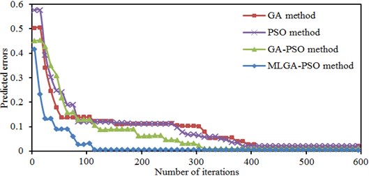
Fig. 17Comparison of radiated noises between original and optimized results
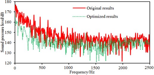
a) Radiated noises in the near field
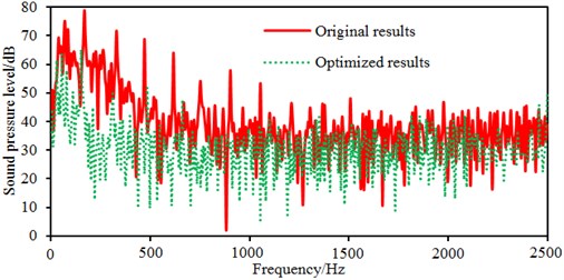
b) Radiated noises in the far field
After the optimization was completed, the amount of blades was 9, the impeller inlet diameter was 230 mm, the blade outlet angle was 24° and the impeller outlet width was 14 mm. According to these parameters optimized by MLGA-PSO algorithm, the centrifugal pump was redesigned and radiated noises in the near-field and far-field were computed to be compared with the original one, as shown in Fig. 17. Peaks of radiated noises at 400 Hz, 490 Hz, 650 Hz, 900 Hz, 1000 Hz and 1150 Hz were obviously reduced in the near-field. At most frequency points, the radiated noise of centrifugal pumps in the near-field has been reduced. In addition, peaks of radiated noises at 200 Hz, 400 Hz, 490 Hz, 650 Hz, 900 Hz and 1150 Hz were obviously reduced in the far-field. When the analyzed frequency was less than 1000 Hz, optimized results of radiated noises in the near-field and far-field were more obvious. Furthermore, the optimized noise presented more valleys in the near-field and far-field. Although the radiated noise of the optimized results was more than the original one in some frequency bands, total values of the optimized noise were 181 dB and 74 dB, respectively, lower than the original noise 190 dB and 89 dB, respectively. The total value of radiated noises in the near-field was reduced by 4.7 % and that in the far-field was reduced by 16.9 %. It is clearly that the optimized centrifugal pump presented an obvious noise reduction effect. Contours of radiated noises of the optimized centrifugal pump were extracted as shown in Fig. 18 and Fig. 19, and they were compared with the original one, showing that the radiated noise was obviously reduced.
Fig. 18Contours of radiated noises in the near-field
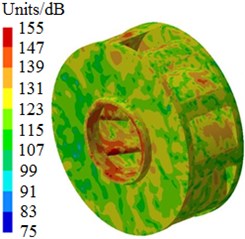
a) 400 Hz
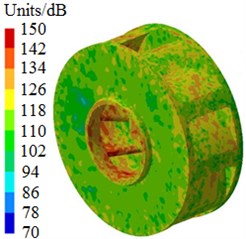
b) 650 Hz
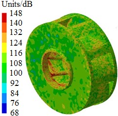
c) 1150 Hz
Fig. 19Contours of radiated noises in the far-field
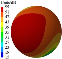
a) 400 Hz
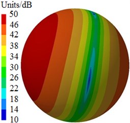
b) 650 Hz
c) 1150 Hz
5. Conclusions
The paper combines a novel MLGA-PSO algorithm with simulation technologies to complete a multi-objective optimization of the centrifugal pump, where parameters including inlet diameter, impeller blade outlet width, blade outlet angle and amount of blades are as designed variables. Optimized results are compared with the original one. Additionally, the simulation model for flow noises and flow fields is validated by the experimental one, and the followed conclusions can be obtained.
1) Radiated noises in the near field are completely induced by fluids in the centrifugal pump. However, radiated noises in the far field are also caused by induction of fluids and vibrations of volutes. With the increase of the analyzed frequency, the sound pressure in the impeller reduces obviously. Sound pressures corresponding to the outlet of the centrifugal pump are more than that in other positions.
2) In order to verify advantages of MLGA-PSO algorithm in the global search ability, optimized speed and stability, GA, PSO and GA-PSO algorithms are chosen in this paper to conduct the compared experiment. Results show that the proposed MLGA-PSO algorithm has higher efficiency and accuracy.
3) Total values of optimized noises in the near-field and far-field are 181 dB and 74 dB respectively, lower than the original noise 190 dB and 89 dB. The total value of radiated noises in the near-field was reduced by 4.7 % and that in the far-field was reduced by 16.9 %. It is clearly that the optimized centrifugal pump presented an obvious noise reduction effect.
References
-
He T. B., Ju Y. L. Design and optimization of natural gas liquefaction process by utilizing gas pipeline pressure energy. Applied Thermal Engineering, Vol. 57, Issue 1, 2013, p. 1-6.
-
Li J., Deng G., Luo C., et al. A hybrid path planning method in unmanned air/ground vehicle (UAV/UGV) cooperative systems. IEEE Transactions on Vehicular Technology, Vol. 65, Issue 12, 2016, p. 9585-9596.
-
Wen C., Cao X., Yang Y., et al. Numerical simulation of natural gas flows in diffusers for supersonic separators. Energy, Vol. 37, Issue 1, 2012, p. 195-200.
-
Han Z. Y., Weng W. G. An integrated quantitative risk analysis method for natural gas pipeline network. Journal of Loss Prevention in the Process Industries, Vol. 23, Issue 3, 2010, p. 428-436.
-
Minggao T., Yong W., Houlin L., et al. Effects of number of blades on flow induced vibration and noise of centrifugal pumps. Journal of Drainage and Irrigation Machinery Engineering, Vol. 30, Issue 2, 2012, p. 131-135.
-
Si Q. R., Yuan S. Q., Yuan J. P., et al. Investigation on flow-induced noise due to backflow in low specific velocity centrifugal pumps. Advances in Mechanical Engineering, 2013, https://doi.org/10.1155/2013/109048.
-
Liu H., Ding J., Dai H., et al. Numerical research on hydraulically generated vibration and noise of a centrifugal pump volute with impeller outlet width variation. Mathematical Problems in Engineering, 2014, p. 620389.
-
Yang A., Lang D., Li G., et al. Numerical research about influence of blade outlet angle on flow-induced noise and vibration for centrifugal pump. Advances in Mechanical Engineering, Vol. 6, 2014, p. 583482.
-
Jiang Y. Y., Yoshimura S., Imai R., et al. Quantitative evaluation of flow-induced structural vibration and noise in turbomachinery by full-scale weakly coupled simulation. Journal of Fluids and Structures, Vol. 23, Issue 4, 2007, p. 531-544.
-
Liu Q., Qi D., Tang H. Computation of aerodynamic noise of centrifugal fan using large eddy simulation approach, acoustic analogy, and vortex sound theory. Proceedings of the Institution of Mechanical Engineers, Part C: Journal of Mechanical Engineering Science, Vol. 221, Issue 11, 2007, p. 1321-1332.
-
Wolfram D., Carolus T. H. Experimental and numerical investigation of the unsteady flow field and tone generation in an isolated centrifugal fan impeller. Journal of Sound and Vibration, Vol. 329, Issue 21, 2010, p. 4380-4397.
-
Dong L., Dai C., Kong F. Y., Fu L., Xia B. Flow-induced exterior noise characteristics of a centrifugal pump as a turbine and different noise’ contribution analysis. Journal of Vibration and Shock, Vol. 35, Issue 5, 2016, p. 169-174.
-
Si Q. R., Yuan S. Q., Yuan J. P. Experimental study on the influence of impeller-tongue gap on the performance and flow-induced noise characteristics of centrifugal pumps. Journal of Vibration and Shock, Vol. 35, Issue 3, 2016, p. 164-168.
-
Dong L., Dai C., Kong F., et al. Impact of blade outlet angle on acoustic of centrifugal pump as turbine. Transactions of the Chinese Society of Agricultural Engineering, Vol. 31, Issue 6, 2015, p. 69-75.
-
Liu H., Ding J., Tan M., et al. Analysis and experimental of centrifugal pump noise based on outlet width of impeller. Transactions of the Chinese Society of Agricultural Engineering, Vol. 29, Issue 16, 2013, p. 66-73.
-
Dai C., Kong F. Y., Feng Z. Z., Bai Y. X. Numerical and experimental investigation of flow-induced noise in centrifugal pump as turbine. Journal of Huazhong University of Science and Technology, Vol. 42, Issue 7, 2014, p. 17-21.
-
Dai C., Kong F., Dong L., et al. Hydraulic and acoustic property optimization for centrifugal pump as turbine based on response surface method. Transactions of the Chinese Society of Agricultural Engineering, Vol. 31, Issue 15, 2015, p. 40-47.
-
Si Q., Lin G., Yuan S., et al. Multi-objective optimization on hydraulic design of non-overload centrifugal pumps with high efficiency and low noise. Transactions of the Chinese Society of Agricultural Engineering, Vol. 32, Issue 4, 2016, p. 69-77.
-
Shouqi Y., Wenjie W., Ji P., et al. Multi-objective optimization of low-specific-velocity centrifugal pump. Transactions of the Chinese Society of Agricultural Engineering, Vol. 31, Issue 5, 2015, p. 46-52.
-
Wei W., Song H., Li W., et al. Gradient-driven parking navigation using a continuous information potential field based on wireless sensor network. Information Sciences, Vol. 408, 2017, p. 100-114.
-
Li J., He S., Ming Z., et al. An intelligent wireless sensor networks system with multiple servers communication. International Journal of Distributed Sensor Networks, Vol. 11, Issue 8, 2015, p. 960173.
-
Du J., Xiao P., Wu J., et al. Design of isotropic orthogonal transform algorithm-based multicarrier systems with blind channel estimation. IET Communications, Vol. 6, Issue 16, 2012, p. 2695-2704.
-
Xiao P., Wu J. S., Cowan C. F. N. MIMO detection schemes with interference and noise estimation enhancement. IEEE Transactions on Communications, Vol. 59, Issue 1, 2011, p. 26-32.
-
Song W. W., Li D. S., Fu J., et al. Micro genetic algorithm based optimization low specific speed pump impeller. Fluid Machinery, Vol. 42, Issue 4, 2014, p. 42-46.
-
Ding G., Tan Z., Wu J., et al. Indoor fingerprinting localization and tracking system using particle swarm optimization and Kalman filter. IEICE Transactions on Communications, Vol. E98B, Issue 3, 2015, p. 502-514.
About this article

