Abstract
The contemporary deployment of unmanned aerial vehicles (UAVs) for commercial purposes and electromagnetic pulse (EMP) threat to mechatronic devices necessitates the study of EMP on surveillance UAVs. This research paper describes the effect of EMP interference on the structure, communication and cabling circuit of the UAV. This was achieved using the CST microwave studio with an induced plane wave referring to MIL-STD464 and applying the transmission line matric solver method. The cable field coupling for bi-directional, uni-directional radiation and uni-directional irradiation were carried out with a constant resistive load of 50 Ω and the induced coupling currents and voltages, current in space domain, TLM mesh is obtained indicating the susceptibility of the UAV under different conditions of EMP interference and the electromagnetic distribution in the UAV circuit layout. Experimentally, the UAV is setup with an EMP generator and its response was observed at 12 m, 10 m and 8 m from the radiation source with the corresponding field strengths.
1. Introduction
In 1946, the USA carried out series of nuclear tests and a new physical phenomenon was discovered which was accompanied by the emergence of a powerful impulse carrying charges that caused damages to the electronics devices within a certain range but the significance and magnitude of the damages caused were not ascertained immediately. From 1958 to 1962 the USA and the Soviet Union conducted series of high burst tests and it was divulged that the high altitude electromagnetic pulse can damage electronic components by inducing charges and referred to as electromagnetic pulse (EMP). By definition, EMP is a high frequency transient paroxysm of electromagnetic energy that produces large electric field which is caused by rapid acceleration of charged particles either natural or manmade. Lightning is the natural form of EMP and occurs when the atmosphere is saturated with excessive charged particles, whereas manmade or intentional electromagnetic pulse are created using an EMP generator. Electromagnetic pulse energy frequencies are from zero hertz to gigahertz (GHz) [1]-[2] depending on the source of the pulse and can be transferred by magnetic field, electrical field, electrical conduction, and electromagnetic conduction.
Advances in aeronautics, embedded systems and engineering sprouted the design of unmanned aerial vehicles (UAV) earlier referred to as flying vehicles which operates without the presence of a human pilot on board and uses aerodynamic forces to provide vehicle lift [3]. The first recorded use was in 1849 by the Australians as a weapon. The UAV is dependent on the unmanned aircraft system (UAS) which consists of the ground/remote controller, communication module (transmitter and receiver), actuators, sensors, computing power, power supply and recording system. UAVs can range from the size of an insect to traditional jets and outfitted with high powered cameras, thermal imaging devices and laser radar [4]. Anti-drone technologies are developed which by computer vision can spot incoming UAV approaching, its speed, features and security threats. When UAVs operate outside their permitted air space and enters into a no flight or enemy zone in space it can be stopped or destroyed by hacking using signal substitution, shooting with guns and jamming using EMP.
2. Principles of uav and effect of emp
2.1. Components and operations
The UAV for this research is modelled according to the design of the DJI Mavic pro with precision in its dimensioning, material properties and air gaps. DJI Mavic pro is a popular UAV used for surveillance and aerial photography consisting of two sets of identical fixed propellers in both clockwise and anticlockwise directions. The variations of the directional movements in this propellers influence the lift and torque whereas the flight direction is altered by varying the speeds on the individual propellers thereby changing the thrust and torque load using a microcontroller.
Computing: Advancements in in computing technologies from analogue systems to microcontrollers and single board computers are incorporated into the UAV with DJI go 4 mobile application and remote controller connected to the UAV.
Remote controller: the remote controller with an operating frequency range of 2.4 GHz to 2.483 GHz transmits signals to the UAV at a maximum range of 7 Km distance which is also connected to a mobile device by a universal serial board cable to navigate the UAV.
Recorder: the camera captures aerial data when the UAV is on operation with a CMOS1/2.3 and total pixels of 12.71M, ISO range of 3200 and electronic shutter speed transmitting images in JPEG and DNG formats
Sensors and actuators: in general function, the sensors are air pressure sensor, gyroscope, obstacle avoidance sensor, optical flow sensor, temperature sensor and GPS sensors.
Communication module: the DJI Mavic receives command and transmits data via a Wi-Fi module with a frequency of 2.45 GHz to 5.75 GHz connecting the UAV to the remote controller and a mobile phone.
Aircraft: the aircraft with a weight of 743 g and a diagonal size of 335 mm has a maximum speed of 40 mph at a maximum flight time of 27 minutes.
2.2. Effect of EMP on UAV
1) Structure: EMP attack has a very minimal effect on the UAV except in cases of higher electromagnetic pulse (HEMP) which are caused by nuclear detonations and earthquakes. Hollow solids with internal electrical wirings are susceptible to HEMP, the magnitude of charges destroys the internal circuit and components resulting to damage on the structure.
2) Cabling and circuit: EMP interferes and causes radiated coupling in cables and electrical circuit of UAVs by inducing higher current and voltage to the cables and circuit, the entrance points of this charges are usually the openings in the motors and air vents of the UAV structure.
3) Communication: the communication of the UAV to the ground controller connects at a frequency of 2.4 GHz to 5 GHz, Jamming or intentional EMP interference radiates continuous waves at frequencies between 2.4 to 5.8 GHz and this interferences breaches connection between the UAV and ground remote controller, thus disrupting the UAV following a preset path. However, UAVs can utilize different frequencies for remote control and image transmission, satellite navigation can be duplicated by inertial systems not susceptible to electromagnetic attack [5]. In the context of this research, the communication module is limited to a Wi-Fi, an intentional EMP interference would disrupt the communication system but not enough to destroy the UAV. DJI Mavic pro is equipped with a return to home feature which autonomously pilots the UAV back to its take off location in the event of interference in its communication.
2.3. Transmission line matrix (TLM)
TLM is a space and time discretizing method for computation of electromagnetic fields based on the analogy between the mesh of the transmission line and electromagnetic field. According to Huygens’s theory of light propagation, R. L. Beurle and P. B. Johns proposed the TLM method in 1971 and practiced on scattering of two dimensional waveguides. Further study and development formed the complete time domain electromagnetic radiation and scattering method. Solving the problems in electromagnetic field distribution in a medium using TLM, the dielectric properties are substituted by matrix which is composed of all nodes formed by spatial discretization representing properties of different media. The distribution of time and space changes in the field are obtained by iterative operations and simultaneously the Fourier transform of the time domain response is established in a wide frequency range. The two dimensional (2D) approach is composed of transmission line meshes connected in parallel and the pulse source with same characteristics impedance are incident from four branches and transmitted to the adjacent nodes by scattering [6]. Considering Kirchhoff’s laws of shunt transmission, the wave equation is written as:
Assuming the transmission line is lossless and nondispersive, the acoustic wav equation for pressure has the form:
where, , , .
The scattering method matrix is applied to study the equivalent network and determines the output at all ports:
The presence of a media in TLM mesh is to modify the scattering matrix and the voltage reflected at any port at time will be:
Assuming the losses are distributed continuously, the amplitude of the reflected wave is attenuated and implemented in the TLM code using the relation:
Thus, the excitation function obtained as the Fourier transform of time response is given as:
3. Simulation study in CST
The UAV model is imported in STEP format, the skin material is set as polyimide (lossy) material and the materials of the motors and inner boards are annealed copper and perfect electrical conductor (PEC) materials respectively.
Fig. 1Cable model under EMP irradiation
Cable and schematic model: The modelling of the cable with single, twisted and ribbon cables are designed from nodes and segments and configuring a cable bundle to the paths.
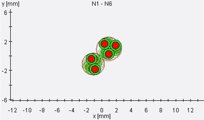
Fig. 2Cross sectional view of a twisted pair cable bundle
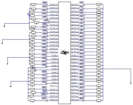
The schematic circuit is generated from the design of the cables in the 3D model with distributed parameter network, each pin is connected to a 50 Ohms resistor attached to ground and a probe in between the resistor and pin.
Fig. 3Schematic/spice model
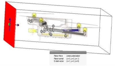
Cable simulation configuration: Frequency range of 0-100 MHz is set with background material as normal and an equidistant of 25 in all directions with an open boundary setting applied. The field monitor for E-field, H-field, surface current, power, current H-energy, E-energy, loss and far field broadband are added with the global properties configured to hexahedral TLM. The probes are inputted with their corresponding coordinates and the setup solver with an accuracy of –30.0 dB.
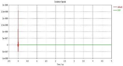
Excitation signal: The EMP signal is double exponential with an amplitude of 65,000 and used as a reference for the default (TLM) signals. The parameters of the EMP waveform refer to MIL-STD464A with peak field strength of 50 kV/m.
Fig. 4Excitation signals
Radiation of energy to produce interference to another electronic system is known as jamming the condition is created by emission of electromagnetic signals for the purpose of disrupting the signals in the other system and can be utilized for narrow and wideband portions in the electromagnetic spectrum.
Table 1Radiated coupling current and voltage for different EMP modes
Bi-directional | Uni-directional irradiation | Uni-directional irradiation | |
Radiated coupling current () | 0.65 | 42 | 0 |
Radiated coupling voltage () | 30 | 2300 | 0 |
Time (us) | 0.06 | 0.08 | 0 |
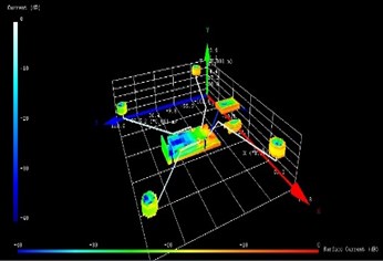
Fig. 5Surface current in time space domain
The Table 1 represents the values in simplified form from the various EMP waveforms in the figures from Figs. 11-16 in the appendix section.
P19 is the cable line on pin N30 RC-1-1 and it’s the longest single cable in the circuit while P52 represents the cable line on N18_SW_4 and the shortest single cable line in the circuit of the UAV model. The induced coupling current and voltage are 0.015 A, 0.6 A on P19 and 0.008 A, 0.3 A on P52. The Figs. 17-20 in the appendix section shows the waveform for both current and voltage of these cable lines.
The Fig. 5 shows the TLM surface current in time space domain, the current concentration is more on the PEC materials closer to the source of the EMP radiation unlike the annealed copper motors.
4. Experiment and result
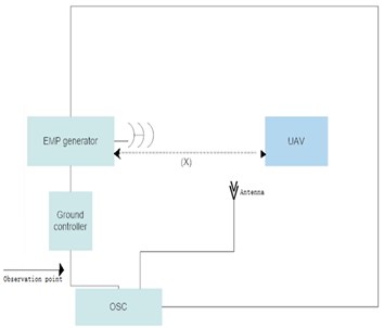
The block diagram illustrates the experiment setup when the effect of electromagnetic pulse interference on UAV is been investigated. We ensure that; The oscilloscope was connected at safe distance from the EMP environment, the aluminum foil was used to cover exposed parts and components to prevent EMP interferences, the remote controller was operated outside the EMP environment and that no conduction/current carrying line was left open.
Fig. 6Flowchart of experimental process
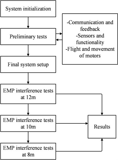
Fig. 7Experimental block diagram
When the sensor or core processor of the UAV is disturbed or damaged due to electromagnetic pulse, the attitude of the UAV will deviate from the ideal value. If the UAV is light, it will continue to shake and fly, and in extreme situations, it will overturn and crash. The UAV used in this study uses light wood as the skeleton and the electronic equipment of the UAV.
Table 2Summary of UAV behavior under EMP attack
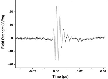
EMP phase | Field strength (kV/m) | Distance f UAV from radiation source (m) | UAV response |
Interference | 22 | 12 | Motors rotate at a non-uniform speed |
Stalling | 22.4 | 10 | Motors stall for first five seconds and rotates non-uniformly at a slower speed |
Out of control | 24 | 8 | UAV delays response to ground controller and motors stalls and rotates inconsistently |
The Table 2 simplifies the values of the waveform represented graphically in Figs. 8-10.
Fig. 8Field strength at interference phase
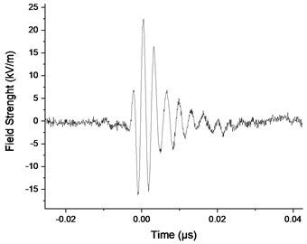
Fig. 9Field strength at stalling phase
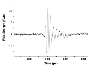
Fig. 10Field strength at out of control phase
5. Conclusions
Studying the effect of electromagnetic pulse (EMP) interference on surveillance unmanned aerial vehicle (UAV) using CST simulation software, we can establish that the peak time of induced current is consistent with lightning and the UAV is more susceptible to attack with a cable field coupling of uni-directional irradiation than bi-directional field coupling and has no observable effect on uni-directional radiation. Furthermore, the length of the cables affects the induced coupling current and voltage with a shorter cable having lower induced current and voltage, therefore a circuit with shorter cable configuration will be less susceptible to EMP attack.
Experimentally, the UAV was observed to be more unstable with the increase in the field strength, with a peak field strength of 24 kv/m and a distance of 8 m the UAV was out of control. Determining the induced current and voltage in the UAV circuit and wires is not feasible with the set of tools and technology available for this research work. Thus, we can only observe its behavior and not the level of damage on its circuit and the value of current or voltage causing the damage.
References
-
X. Li, Q. Wang, X. Zhou, and S. Qin, “The research of electromagnetic conducted coupling in transmission-line networks,” in 2011 International Conference on Electronics and Optoelectronics (ICEOE), Vol. 3, Jul. 2011, https://doi.org/10.1109/iceoe.2011.6013313
-
S.-Q. Zheng, D.-Y. Hou, D.-D. Wang, and F. Deng, “Electromagnetic pulse protection requirements and test methods for systems,” in 2012 10th International Symposium on Antennas, Propagation & EM Theory (ISAPE - 2012), pp. 857–860, Oct. 2012, https://doi.org/10.1109/isape.2012.6408907
-
X. Li and L. Yang, “Design and implementation of UAV intelligent aerial photography system,” in 2012 4th International Conference on Intelligent Human-Machine Systems and Cybernetics (IHMSC), Vol. 2, pp. 200–203, Aug. 2012, https://doi.org/10.1109/ihmsc.2012.144
-
D. V. Brovchenko, “Application features of UAVs different types,” in 2015 IEEE International Conference Actual Problems of Unmanned Aerial Vehicles Developments (APUAVD), pp. 26–29, Oct. 2015, https://doi.org/10.1109/apuavd.2015.7346548
-
K. Yu Sakharov, A. V. Sukhov, V. L. Ugolev, and Y. M. Gurevich, “Study of UWB electromagnetic pulse impact on commercial unmanned aerial vehicle,” in 2018 International Symposium on Electromagnetic Compatibility (EMC EUROPE), Vol. 2018, pp. 40–43, Aug. 2018, https://doi.org/10.1109/emceurope.2018.8484992
-
C. Chen, et al., “Simulation and analysis of EMP transient electromagnetic effect of aircraft,” The Journal of Engineering, Vol. 2019, No. 16, pp. 2464–2467, Dec. 2018, https://doi.org/10.1049/joe.2018.8615
-
V. Venkateswarlu, R. Sarathi, and Y. Narayana Rao, “Modelling of an electromagnetic pulse simulator and evaluation of its radiated field,” in 1995 International Conference on Electromagnetic Interference and Compatibility (INCEMIC), pp. 184–189, 1995, https://doi.org/10.1109/icemic.1995.501581
-
E. P. Flynn, “Low-cost approaches to UAV design using advanced manufacturing techniques,” in 2013 3rd IEEE Integrated STEM Education Conference (ISEC), Mar. 2013, https://doi.org/10.1109/isecon.2013.6525199
-
Y. Wei, H. Qiu, Y. Liu, J. Du, and M.-O. Pun, “Unmanned aerial vehicle (UAV)-assisted unmanned ground vehicle (UGV) systems design, implementation and optimization,” in 2017 3rd IEEE International Conference on Computer and Communications (ICCC), Vol. 2018, pp. 2797–2801, Dec. 2017, https://doi.org/10.1109/compcomm.2017.8323042
-
Y. A. Pederi and H. S. Cheporniuk, “Unmanned aerial vehicles and new technological methods of monitoring and crop protection in precision agriculture,” in 2015 IEEE International Conference Actual Problems of Unmanned Aerial Vehicles Developments (APUAVD), pp. 298–301, Oct. 2015, https://doi.org/10.1109/apuavd.2015.7346625
Cited by
About this article

The authors acknowledge the support of the Mechanical Engineering Department of Nanjing University of Science and Technology, Nanjing, Jiangsu China.
