Abstract
In an engineering practice, the faults of rolling bearing are mostly represented as being compound and hard to diagnose. For that, intrinsic time-scale decomposition (ITD) algorithm was combined with Auto-correlation Function (AF) to extract the characteristics of compound faults of rolling bearing in aviation engine. Firstly, ITD algorithm was used to decompose acceleration signal into multiple rotational and residual trend component; secondly, rotational components were reconstructed to figure out their AF; finally, characteristic frequency of rolling bearing under compound faults mode was extracted by Hilbert spectrum envelope. To validate the effectiveness of the method, a comparative study on sensor installation positions and vibration acceleration signal of different compound faults has been carried out. The result of study shows that the proposed ITD-AF method is capable to extract compound fault characteristics of rolling bearing in an effective and precise manner and the installation positions of sensors, rotation speed and fault type shows insensitivity to extraction.
Highlights
- ITD signal decomposition algorithm is used to decompose the rolling bearing composite fault signal.
- AF algorithm is used to reduce noise of reconstructed signal.
- Characteristic frequency of rolling bearing under compound faults mode was extracted by Hilbert spectrum envelope.
- A comparative study on sensor installation positions and vibration acceleration signal of different compound faults has been carried out.
- Analysis and comparison of the proposed method with the mainstream method.
1. Introduction
Rolling bearing is one of critical components of aero motor, for which it becomes very important to have effective monitoring on its running status. As vibration signal contains the characteristic information of various operating conditions of rolling bearing, researchers, domestic and overseas, have made extensive and further studies on the fault diagnosis and characteristic extraction of rolling bearing on the basis of acceleration vibration signals. Liu Xiaofeng, et al. brought forward a fault diagnosis method basic on wavelet packet and empirical mode decomposition [1], the diagnosis shows that the fault frequency can be extracted effectively, and it is easy to judge and distinguish the fault type; envelope analysis of wavelet packet was also applied to fault diagnosis of rolling bearing by researchers [2, 3], for example, an automatic diagnosis method basic on wavelet packet coefficients, kurtosis and envelope analysis was proposed according to the vibration characteristics of rolling bearing; Li Yongbo, et al. put forward an improved Empirical Mode Decomposition methodology to validate its effectiveness [4], compared with the EMD algorithm, it shows that the improved algorithm in the field of fault diagnosis is also applicable. Though EMD is effective in the analysis of bearing vibration signal, the precision of result is to a large extent dependent to the option of envelope interpolation algorithm. Wang, et al. successfully extracted the information of mechanical failure from vibration signal by constraint independent component analysis, and validated the effectiveness of analysis through actual measurement of bearing fault data [5]. Yu proposed a new analytical method for fault diagnosis of weak signal of aviation hydraulic pump [6]. Liang Yu, et al. contributed a fault diagnosis method basic on Adaptive Fourier decomposition, which worked by classifying original bearing signal cluster into two types through fuzzy c-means. The single components of larger kurtosis are summated as bearing fault carrier signal and demodulated resonance technique was applied to diagnose and locate a fault [7]. In considering the complexity of characteristic signal of bearing and interference of noise signal, Mark G, Frei and Ivan Osorio proposed ITD algorithm which was a self-adaptive time-frequency analysis method [8-11], ITD algorithm has superior adaptability and can decompose the fault signal into several intrinsic rotation components. In recent years, ITD algorithm has been introduced by some scholars into fault diagnosis [12-14], including the faults of diesel engine, centrifugal pump and bearing. In the fault diagnosis of bearings, Cheng Junsheng, et al. decomposed vibration signal of rolling bearings with ITD algorithm and got several components of proper rotation, the ones of which containing fault information were extracted for permutation entropy as fault characteristic value; classifier of Variable Predictive Model Based Class Discriminate was trained and at last, which was introduced to make fault diagnosis and classification [15], the experimental results show that this method can be effectively used for fault diagnosis of rolling bearing. Yu combined ITD algorithm with Graph Signal Processing (GSP) theory for fault diagnosis research [16]. In the consideration that self-correlation function of signal is capable to maintain signal periodicity while eliminating noise, the self-correlation function has taken a certain role in the fault diagnosis of rolling bearings, for example, Research scholar Mohamed El Morsy combined self-correlation function and fault analysis [17] and made the diagnosis through Cepstrum analysis. Mantas Landauskas et al. proposed a bearing fault diagnosis method based on permutation entropy pattern classification and proved the effectiveness of the proposed early defect detection and classification method [18]. Due to the efforts of scholars around the world, fault diagnosis technology of rolling bearing has made a remarkable progress. However, most of current studies mainly concentrate on the single fault of rolling bearing rather than composite ones [19]. H. Hotait proposed an automatic and optimized method to detect and track real-time rolling bearing defects in his paper [20]. As found by the research and analysis in engineering practice, the faults of rolling bearing are often manifested as being composite instead of single, but to extract the characteristics of composite faults is much harder than single ones [21]. The effects of noise, interaction between components and signal transmission contributes to the fact that the faults of rolling bearings tend to be complex and weak in the vibration signal. In view of this, ITD algorithm is combined with AF to complete the research on extracting the characteristic frequency of rolling bearings under the different compound fault types.
2. Theory
2.1. ITD algorithm theory
Complex acceleration vibration signals are decomposed by ITD algorithm into the sum of multiple independent components of proper rotation (PR) and a residual component term. Given vibration signal is represented by , and operator by defining baseline signal, decomposition algorithm of complex signal is represented as:
1) Decompose the vibration signal into the sum of signal and component :
2) The segmented baseline signal extraction operator is derived from the baseline signal , the definition formula is as follows:
Thereinto, represents extreme point of acceleration vibration signal, the time corresponding to extreme point, is defined as:
The linear gain parameter is a constant 0.5.
3) Treat baseline signal as a new acceleration vibration signal, and it is decomposed until the baseline signal is decomposed into a monotonic function.
ITD algorithm decomposition is finally expressed as:
In which, is the extraction operator of PR component, residual trend component.
2.2. Auto-correlation function
Signal auto-correlation function can reserve the periodic component and eliminate noise at the same time, and meanwhile can change frequency modulation to amplitude modulation [22].
A continuous signal is defined, then , the auto-correlation function of continuous such that:
Given , and * is respectively delay factor, statistical mean value and complex convolution.
2.3. Rolling bearing characteristic frequency
In view of the one-to-one correspondence between characteristic frequency and fault type of rolling bearing, we can take advantage of this to diagnose the faults of rolling bearings and distinguish the compound fault type [1, 4, 6]. In other words, once a component fails, the corresponding fault feature frequency or multiple frequency will be extracted from the signal analysis. The calculation formula of characteristic frequency is as Eqs. (6)-(10), and each letter is defined as shown in Table 1.
Table 1Rolling bearing parameters
Indicators | Physical meaning |
Rotation frequency | |
Inner ring fault characteristic frequency | |
Outer ring fault characteristic frequency | |
Rolling element fault characteristic frequency | |
Retainer fault characteristic frequency | |
Rotation speed | |
The rolling element number | |
Bearing diameter | |
Bearing pitch |
Rotation frequency:
The frequency of inner ring fault:
The fault frequency of outer ring:
The fault frequency of rolling element:
The fault frequency of retainer:
3. Compound fault experiment and feature extraction
3.1. Compound fault feature extraction
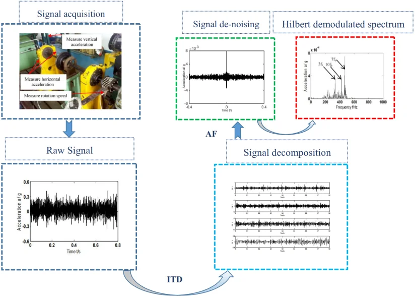
ITD algorithm was combined with AF to precisely abstract the fault characteristics frequency of rolling bearing under the compound fault mode. Firstly, obtained vibration signal was broken down into PR and residual trend components by ITD algorithm; secondly, rotational components were reconstructed and the new reconstructed signal is processed by AF; finally, considering that the vibration signal will be modulated when rolling bearing faults occur. Meanwhile, Hilbert transform can obtain the complex envelope of signal which removes regular vibration component and only contains signal modulated information without the load frequency composition [23]. Therefore, Hilbert envelope analysis was given to the AF and then characteristics of compound faults were distilled by the spectrum envelope obtained. Traditional usage of ITD algorithm for fault diagnosis is shown in Fig. 1(a) and specific procedure of ITD-AF algorithm is shown in Fig. 1(b).
By comparing Fig. 1(a) and Fig. 1(b), the difference can be found in:
1. A traditional study (scheme A) mostly concentrates on single faults of rolling bearing, while the study in this paper (scheme B) focuses on the extraction of characteristics of compound faults.
2. A traditional study (scheme A) reconstructs rotational components in straight-forward manner to distill the characteristic frequency of faults, while the study in this paper (scheme B) uses AF analysis procedure to reduce the noise of the reconstructed PR component, and distills the characteristic frequency of the compound fault by Hilbert envelope spectrum analysis.
3.2. Rolling bearing fault experiment
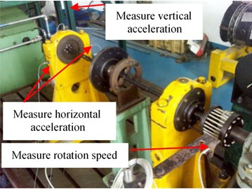
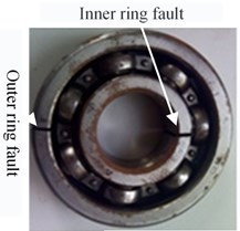
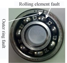
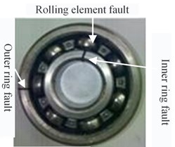
All the data of rolling bearing in this article comes from aviation engine rotor rolling bearing experimental rig. Acceleration vibration signal was collected by Danish acceleration sensor model B&K4508 and NSB9234 data acquisition equipment’s from National Instruments company. Electric spark cutting was used to simulate the damage of each component of bearing (Cutting depth 0.2 mm). Fig. 2(a) reveals the installation sites of bearing experimental rig as well as sensors. Fig. 2(b-d) shows the compound failure of outer and inner rings of rolling bearing; outer ring and rolling element; outer ring, inner ring and rolling element.
Fig. 1Method flow diagram
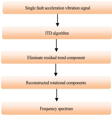
a) Scheme A
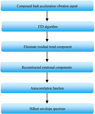
b) Scheme B
Fig. 2a) Aircraft engine rotor rolling bearing experimental rig; b)-d) three types of compound faults
a)
b)
c)
d)
4. Feature extraction scheme comparison
As limited by length, the paper firstly took at random the compound failure of inner ring, outer ring and rolling element as a sample. All the sensors chosen randomly were installed in horizontal direction with rotation speed being 1530 r/min. According to Eq. (6)-(10), rotation and failure frequency of outer, inner ring and rolling element can be figured out separately as follow: 25.5 Hz, 65.5 Hz, 113 Hz and 44.4 Hz.
4.1. Scheme A – traditional method
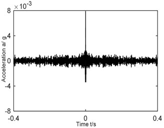
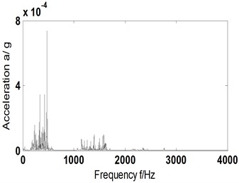
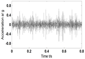
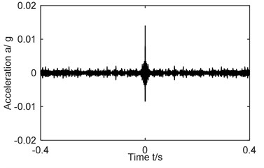
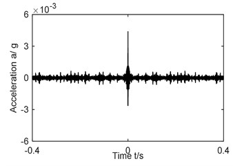
Firstly, according to scheme A (traditional method) described in Section 3.1, characteristics of bearing were studied when composite faults occurred in inner ring, outer ring and rolling element. The results were shown in Fig. 3(a-e). Fig. 3(a) and Fig. 3(b) are the time domain diagram of acceleration vibration signal and the Hilbert spectrum envelope of acceleration vibration signal, respectively; Fig. 3(c) the time domain diagram of PR component after decomposition by ITD algorithm, where PR components have 4 levels, being PR1-PR4; Fig. 3(d) and (e) the time-domain diagram and Hilbert envelope spectrum of reconstructed signal.
Fig. 3Time domain signals and their Hilbert envelope spectrum-scheme A-1530 r/min-inner ring, outer ring and rolling element fault type
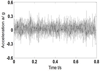
a) Time-domain acceleration signal
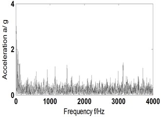
b) Hilbert envelope spectrum of Fig. 3(a)
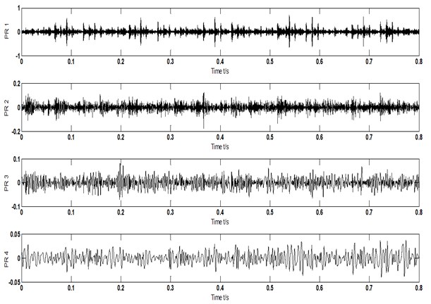
c) Rotational components of acceleration signal-ITD
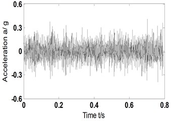
d) Time domain signal-reconstructed signal
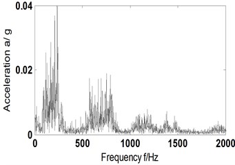
e) Hilbert envelope spectrum of reconstructed signal
It can be found from Fig. 3(b) and (e) that traditional method (scheme A) cannot obtain the effective fault frequency of composite faults no matter by Hilbert envelope spectrum analysis of original signal or spectral analysis of reconstructed PR components (with residual trend terms eliminated). That means the traditional method has no way to catch a fault of rolling bearing and determines its type.
4.2. ITD-AF: scheme B – A new method
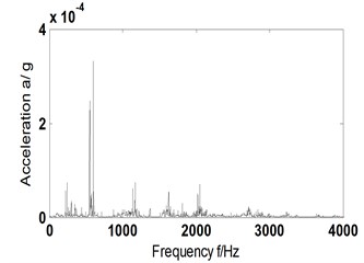
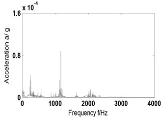
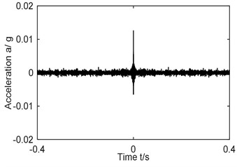
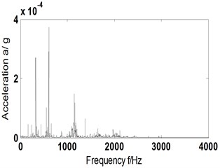
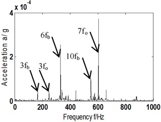
To effectively extract the compound fault characteristics of rolling bearing, a combination of ITD algorithm and AF of signal is the option in this paper. Firstly, compound fault signal was broken down into PR and residual trend components by ITD; secondly, the PR components were reconstructed and the AF of reconstructed signal was figured out; finally, fault characteristics were extracted by spectrum from the AF. For a comparative analysis, acceleration vibration data selected was the same with Section 4.1. According to Eqs. (6-10), characteristic frequencies of each position could be obtained: , , and being 25.5 Hz, 65.5 Hz, 113 Hz and 44.4 Hz separately. The analysis results are shown in Fig. 4(a)-(c), where Fig. 4(a) is the time domain graph of AF of reconstructed signal; Fig. 4(b) the Hilbert envelope spectrum of Fig. 4(a); Fig. 4(c) partial enlargement diagram of Hilbert envelope spectrum of Fig. 4(b).
Fig. 4AF and its Hilbert envelope spectrum-scheme B-1530 r/min
a) AF of reconstructed signal
b) Hilbert envelope spectrum of Fig. 4(a)
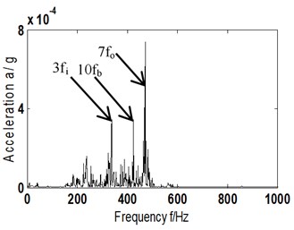
c) Hilbert envelope spectrum local zoom of Fig. 4(b)
After analyzing Fig. 4(b)-(c) and comparing with Fig. 3(b)-(e), it can be found that based on ITD-AF method, there are distinct frequency components in the Hilbert envelope spectrum of reconstructed signal: 338 Hz, 425 Hz, 472 Hz, which corresponds to the 3 times of characteristic frequency of inner ring (113 Hz), tenfold of rolling element (44.4 Hz) and septuple of outer ring (65.5 Hz), respectively.
That means ITD-AF based method can accurately distill the composite fault characteristic frequency of bearing while traditional ITD algorithm cannot.
5. The influence of different factors
5.1. Different directions
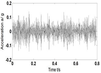
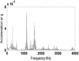
To analyze the impact of proposed ITD-AF method to installation direction of sensors, acceleration vibration signal gathered at the same experiment of chapter 4 by the sensors fixed vertically on experimental rig was chosen for characteristic extraction and the result is shown in Fig. 5. With 1530 r/min and according to Eqs. (6-10), we can get corresponding 25.5 Hz and , and , 65.5 Hz, 113 Hz and 44.4 Hz. Fig. 5(a) is the original signal of compound faults of outer, inner ring and rolling element; Fig. 5(b) the reconstructed signal obtained by ITD; Fig. 5(c) time domain diagram of AF of Fig. 5(b); Fig. 5(d) and (e) Hilbert envelope spectrum of AF of reconstructed signal and its partial enlargement.
Fig. 5AF and its Hilbert envelope spectrum-scheme B-vertical
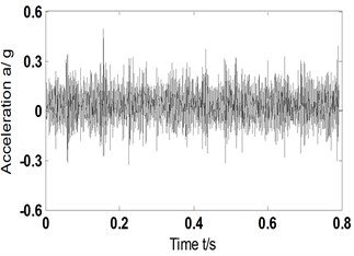
a) Time-domain acceleration signal
b) Time domain signal-reconstructed signal
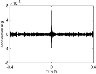
c) AF of reconstructed signal
d) Time domain signal-reconstructed signal
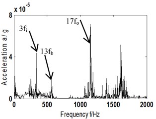
e) Hilbert envelope spectrum local zoom of Fig. 5(d)
It can be found from the comparative analysis between Fig. 5(d)-(e) and 4(b)-(c) that with transducer seated on the perpendicular direction of the experimental rig, ITD-AF (scheme B) method can extract the 3-time frequency (338 Hz) of (113 Hz), 13-time frequency (564 Hz) of (44.4 Hz) and 17-time frequency (1149 Hz) of (65.5 Hz). Though not completely the same with the frequency components of horizontal direction, it corresponds to the fault type of rolling bearing as usual. The result indicates that the mounting direction of the sensor has little effect on diagnosis and analysis.
5.2. Different fault genres
To validate insensitivity of the ITD-AF method to composite fault genres of bearing, a study has been given to other compound faults with the ones of rolling element and outer ring (fault type A), inner and outer ring (fault type B) as illustrations.
The rotating speed was 2000 r/min when the outer ring and rolling element malfunctioned. A sensor was chosen at random and fixed vertically to tester. According to Eqs. (6-10), rotation frequency (2000/60 = 33.3 Hz) and , and can be obtained, which are 147.8 Hz, 85.5 Hz and 58 Hz respectively. When the inner and outer ring malfunctioned, rotation speed is 1511 r/min. Again, a sensor was chosen at random and fixed vertically to tester. According to Eqs. (6-10), rotation frequency , , and can be obtained, which are 25.1 Hz, 64.7 Hz, 111.7 Hz and 43.9 Hz respectively.
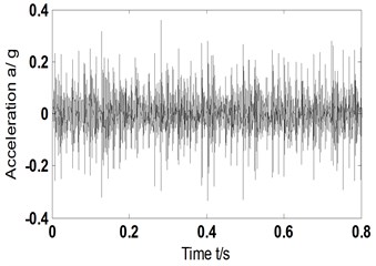
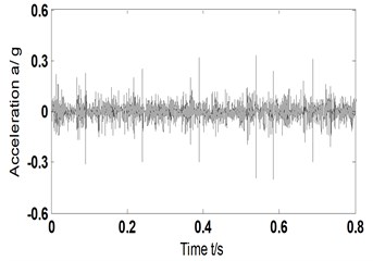
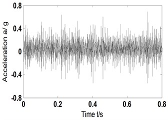
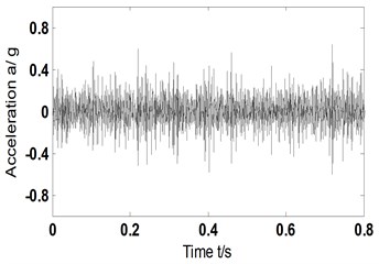
An analysis was given to vibration acceleration signal of compound faults by ITD-AF method and the graph of the research process is shown in Fig. 6, where Fig. 6(a1), (b1) is the time domain signal of acceleration vibration; Fig. 6(a2), (b2) reconstructed signal; Fig. 6(a3), (b3) the AF time domain graph of reconstructed signal; Fig. 6(a4), (b4) and 6(a5), (b5) being Hilbert envelope spectrum of AF and its partial enlargement. Fig. 6(a1-a5) corresponds to the compound fault genres of rolling element and outer ring; Fig. 6(b1-b5) to that of outer and inner rings.
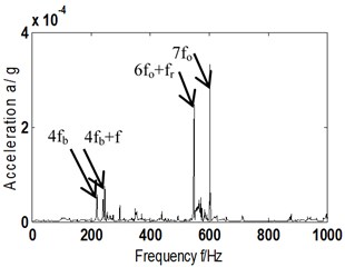
The analysis of Hilbert envelope spectrum in Fig. 6(a5) reveals that it is possible to obtain 4-time frequency (220 Hz) of (58 Hz), 7-time frequency of that of outer ring, and 4 times the sum of fault and rotational frequency of rolling element (248 Hz), and 6 times that of characteristic and rotational frequency of rolling element (549 Hz). Thus, it certain that fault of outer ring and rolling element occurred in bearing. That directly proves the ITD-AF method proposed can determine the composite fault of the outer ring and rolling elements.
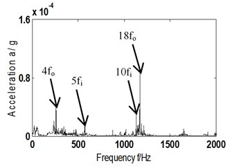
After analyzing Fig. 6(b5), 5-time frequency (572 Hz) and 10-time frequency (1134 Hz) of inner ring fault frequency (111.7 Hz), and 4-time frequency (262 Hz) and 18-time frequency (1176 Hz) of outer ring fault characteristic frequency (64.7 Hz) can be obtained. Consequently, it can be judged that a compound fault of inner and outer ring occurs in the bearing. That means the proposed ITD-AF method can make correct judgment of composite fault type of inner and outer rings.
Based on the proposed ITD-AF method, a study was given to characteristic extraction of original signal of bearings under 3 different compound fault states. The consequence indicates that the ITD-AF approach can distill fault characteristics of bearing in dissimilar states of composite faults and determine fault types, which means ITD-AF method is insensitive to the diagnosis of different types of compound faults in rolling bearings.
Fig. 6a1)-a5) AF and its Hilbert envelope spectrum – fault type A-scheme B; b1)-b5) AF and its Hilbert envelope spectrum – fault type B-scheme B
a1) Time domain acceleration signal-fault type A
b1) Time domain acceleration signal-fault type B
a2) Time domain signal-reconstructed signal – fault type A
b2) Time domain signal-reconstructed signal – fault type B
a3) AF of Fig. 6(a2)
b3) AF of Fig. 6(b2)
a4) Hilbert envelope spectrum of Fig. 6(a3)
b4) Hilbert envelope spectrum of Fig. 6(b3)
a5) Hilbert envelope spectrum local zoom of Fig. 6(a4)
b5) Hilbert envelope spectrum local zoom of Fig. 6(b4)
5.3. Different rotational speeds
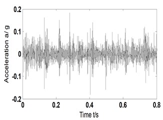
To fully validate the effectiveness of proposed ITD-AF method (scheme B) to distill the characteristic frequency of composite faults of bearings, an analysis was given to the composite faults of rolling element and outer ring in different (2013 r/min). Sensors were chosen at random and installed in vertical direction of experimental rig. According to the Eqs. (6-10), we have , , and : 33.6 Hz, 148.8 Hz, 86.1 Hz and 58.4 Hz, Fig. 7 shows the analysis results. Fig. 7(a) shows the acceleration vibration signal; Fig. 7(b) reconstructed signal; Fig. 7(c) time domain graph of AF; Fig 7(d) and (e) auto-correlative Hilbert envelope spectrum of reconstructed signal and its partial enlargement.
Fig. 7AF and its Hilbert envelope spectrum-fault type A-scheme B-2013 r/min
a) Time domain acceleration signal
b) Time domain signal-reconstructed signal
c) AF-reconstructed signal
d) Hilbert envelope spectrum of Fig. 7(c)
e) Hilbert envelope spectrum local zoom of Fig. 7(d)
Analysis of envelope spectrum diagram Fig. 7(d) and (e) shows that in different rotation speeds, the proposed ITD-AF method can provide triple frequency (166 Hz) of (58.4 Hz), six-fold (331 Hz) and tenfold (551 Hz), as well as triple frequency (248 Hz) of (86.1 Hz) and seven fold (606 Hz). For that, it can be judged that a composite fault of rolling element and outer ring occurs in rolling bearing. This also proves that the proposed ITD-AF method is insensitive to rotation speed.
6. Conclusions
As the faults of rolling bearing in aircraft engine are often represented as compound faults which are weak and complicated, it is impossible to effectively monitor the equipment operation status of rolling bearing and recognize fault genres. To effectively extract the characteristics of compound faults and correctly determine the fault types, we have combined ITD algorithm and self-correlation function of signal to extract the characteristics of compound faults of rolling bearings occurring in different installation directions, types and rotation speeds, and then made a comparison with traditional ITD algorithm. The result shows that traditional ITD algorithm has no way to effectively complete the research of compound fault feature extraction of rolling bearing and thereby makes it impossible to determine a compound fault type. The proposed ITD-AF method can make effective extraction of compound faults without considering the installation direction of the sensor (horizontal and vertical), compound fault types and rotation speed.
References
-
Liu Xiaofeng, Wang Shuhua, et al. A Way to diagnose the rolling bearing fault dealt with wavelet-packet and EMD. Communications in Computer and Information Science, Vol. 237, 2011, p. 364-369.
-
Ma Chuan, Li Hongkun, et al. Rolling bearing fault diagnosis using wavelet packet-kurtosis-envelope. Measurement and Diagnosis, Vol. 31, 2011, p. 720-723.
-
Yin Yufeng, Cai Guoqiang, et al. Fault diagnosis of rolling bearing based on wavelet packet and Fourier analysis. International Conference on Computational Aspects of Social Networks, 2010, p. 703-706.
-
Li Yongbo, Xu Minqiang, et al. An improved EMD method for fault diagnosis of rolling bearing. Prognostics and System Health Management Conference, 2016.
-
Wang Zhiyang, Chen Jin, et al. Constrained independent component analysis and its application to machine fault diagnosis. Mechanical Systems and Signal, Vol. 25, 2011, p. 2501-2512.
-
Yu Mingyue, Cheng, Jincai, et al. A novel method of weakness imbalance fault identification and application in aero-hydraulic pump. Journal of Vibroengineering, Vol. 21, 1, p. 52-65.
-
Liang Yu, Jia Limin, et al. A new approach to diagnose rolling bearing faults based on AFD. International Conference on Electrical and Information Technologies for Rail Transportation, Vol. 288, 2014, p. 573-582.
-
Frei M. F., Osorto I. Interinsic time-scale decomposition: time-frequency-energy analysis and real-time filtering of non-stationary signals. Proceeding of the Royal Society, Vol. 463, 2007, p. 321-342.
-
Restrepo Juan M., Venkataramani Shankar, et al. Defining a trend for time series using the intrinsic time-scale decomposition. New Journal of Physics, Vol. 16, 2014, p. 1-29.
-
Zegadi Ahmed, Zegadi Khalil Kheireddine Trace interpolation and noise attenuation using intrinsic time-scale decomposition. Society of Exploration Geophysicists International Exposition and 81st Annual Meeting, Vol. 2011, 2011, p. 3633-3637.
-
Lewandowski Marcin Application of intrinsic time-scale decomposition in analyzing sigma-delta modulator for audio DAC. Signal Processing – Algorithms, Architectures, Arrangements, and Applications Conference, Vol. 4, 2015, p. 71-75.
-
Liu Min, Zhang Yingtang, et al. Diesel engine fault diagnosis based on singular value energy standard spectrum, intrinsic time-scale decomposition and kernel independent component analysis. Prognostics and System Health Management Conference, 2019, p. 493-499.
-
Zhang Ying, Zhang Chao, et al. Fault diagnosis method for bearing based on improved intrinsic time-scale decomposition and spectrum kurtosis. Acta Energiae Solaris Sinica, Vol. 38, 2017, p. 699-706.
-
Alabied Samir, Hamomd Osama, et al. Fault diagnosis of centrifugal pumps based on the intrinsic time-scale decomposition of motor current signals. 23rd IEEE International Conference on Automation and Computing, 2017, p. 699-706.
-
Cheng Junsheng, Ma Xingwei, et al. Rolling bearing fault diagnosis method based on permutation entropy and VPMCD. Journal of Vibration and Shock, Vol. 33, 2014, p. 119-123.
-
Yu Mingyue, Pan Xiang A novel ITD-GSP-based characteristic extraction method for compound faults of rolling bearing. Measurement, Vol. 159, 2020, p. 107736.
-
Morsy Mohamed El, Achtenová Gabriela Rolling bearing fault diagnosis techniques – auto-correlation and cepstrum analyses. Mediterranean Conference on Control and Automation, 2015, p. 328-334.
-
Landauskas M., Cao M., Ragulskis M. Permutation entropy-based 2D feature extraction for bearing fault diagnosis. Nonlinear Dynamics, Vol. 102, 2020, p. 1717-1731.
-
He Zhengjia, Cao Hongrui, et al. Developments and thoughts on operational reliability assessment of mechanical equipment. Journal of Mechanical Engineering, Vol. 50, Issue 2, 2014, p. 171-186.
-
Hotait H., Chiementin X., Rasolofondraibe L. Optimization automating monitoring based on classification for rolling bearing. Vibroengineering Procedia, Vol. 31, 2020, p. 15-20.
-
Wang Guobiao, He Zhengjia, et al. Basic research on machinery fault diagnosis – what is the prescription. Journal of Mechanical Engineering, Vol. 49, Issue 1, 2013, p. 63-72.
-
Chen Jin, Guangming Dong Cyclostationary Theory and Method of Mechanical Fault Characteristic Extraction. Shanghai Jiao Tong University Press, Shanghai, 2013.
-
Ding Feng, Qin, Fengwei Application of wavelet denoising and Hilbert transform in fault diagnosis of motor bearing. Electric Machines and Control, Vol. 21, Issue 6, 2017, p. 89-95.
Cited by
About this article

This work was supported by National Natural Science Foundation of China (Grant No. 51605309), Natural Science Foundation of Liaoning Province of China (Grant No. 2019-ZD-0219), Aeronautical Science Foundation of China (Grant No. 201933054002) and Provincial Education Department of Liaoning Province of China (Grant No. JYT19042).
