Abstract
The present paper discusses the study of longitudinal vibrations in turbomachines coupled with skewed slotted bar cage induction motors and which are of the typical configurations in refinery industries. Based on vibration data, the severe longitudinal vibrations in tilting pad thrust bearing assembly and its failure mechanism during start up transient and steady-state operations has been observed. The excitation sources for these longitudinal vibrations originates from asymmetric air gaps in cage induction motors. Hereby, the study of longitudinal vibrations in turbomachines with thrust bearing is found to be necessary. A simplified Single degree freedom (SDOF) analytical model is proposed to estimate the peak response based on tuned variable stiffness method. Uniform air gap with rotor skew causes fixed thrust and is proportion to square of the load current. Static eccentricity across the rotor motor air gap causes variations in gap length and intern creates the torque fluctuations. This value is proportional to variance in square of the load current. In the proposed model evaluates the cascade effect of preloaded thrust due to rotor motor skewness and followed by compressor thrust due to differential pressure across the impeller in the form of the variable stiffness. This model has advantage in analysing the coupled motor and turbomachinery system response in longitudinal direction in a simple manner. The longitudinal vibrations estimate at thrust bearing and compared with experimental vibration data obtained from the field machinery. There is a good convergence between results of the analytical model and experimental field vibration data.
1. Introduction
Generally, turbomachinery manufacturers follow established design codes like API 617 [1] for sequential phases of designs to ensure equipment integrity through fluid process designs for freezing the sizing of flow path in the first phase, followed by mechanical design of the compressor components for mechanical strength and metallurgical aspects and finally to tuning out the rotating equipment dynamics. In practice, the centrifugal compressor design codes are being followed so far for general refinery service using the vibrations with respect to lateral and torsional dynamics only. API 684 [2] standard was focused on the recommended practice regarding rotor dynamics for coupled lateral and torsional vibrations only. These design codes consider longitudinal forces as a fixed thrust without considering dynamic effects in longitudinal direction. But, thrust collar failures are observed in gas compressors coupled with cage induction motors, where coupling detachment of boiler feed pumps are observed due to longitudinal forces and vibrations.
Edgar J. Gunter et al. [3] discussed Lund’s contribution in modern compressor designs for rotor bearing system stability by using transfer matrix method and FEM methods. His research work was incorporated in compressor API design codes. Lund’s studied Jeffcott rotor with gas bearings, multi lobed fluid bearings including tilting pad bearings, unbalance response, stability and transient response using Jeffcott model. Whirling of rotors around the origin studied with two degrees of freedom model in polar coordinates for turbo-rotors and analyzed lateral dynamics successfully. T. H. Young et al. [4] studied dynamic stability of rotor-bearing systems subjected to random axial forces. In this study, the coupling between bending and longitudinal vibrations in the shaft is considered without coupled induction motor.
Bradford et al. [5] studied the axial magnetic forces in induction motors. The induction motor was taken as the driving unit and it induced the electromagnetic force component as axial thrust (due to skew in rotor bar slots). The axial displacement was because of variations in the air gap magnetic energies intensities and which causes vibrations. V. Subramanyam [6] made comprehensive analytical study of axial force experienced by the rotor of an induction motor and tried to establish axial force as a function of slip. The calculated forces were compared with strain gauge measurements and the effect of airgap on axial force was studied. Juha Phyhonen et al. [7] discussed design of high speed electrical induction motors to avoid excessive iron loss. They also provided an empirical relation to estimate the nominal airgap as a function of power for induction motor rotating at 3000 rpm and above. Komatani [8] made 3D electromagnetic analysis of cage induction motor with rotor skew slots and with various slot designs of three phase induction motor using Brand ford formulation. Heineman [9] discussed the formulations to calculate the motor torque in terms of current in the proposed induction motor design. Also discussed the selection of motor designs with various angles of skew in squirrel cage induction motor rotors to avoid clogging effect, reduction in current harmonics and noise.
Thomson et al. [10] used the vibration and current signature analysis to diagnose induction motor problems. The frequency associated with the defects in the current signature analysis is a function of rotational speed. Thomson et al. [11] used motor current analysis to diagnose the problems related to motor bar defects and air gap eccentricities. The static and dynamic air gap eccentricity are correlated with the unbalanced magnetic pull (UMP) and rotor motor stiffness and it was concluded that excessive eccentricities cause stress in rotor and damage to the bearings. Costello [12] studied the vibration forces in the induction motors and explained with operating principles. He integrated the vibration diagnostics with rotor dynamics and correlated the unbalanced magnetic pull with eccentricity. Narendra [13] reviewed the eccentric and asymmetry air gap problems in squirrel cage motors. The common eccentric problems in three phase induction motors were modelled with FEM and validated with the motor current analysis data. Tehunen et al. [14] studied the electromagnetic forces acting between the rotor and the stator having an eccentric airgap. For cylindrical circular whirling motion, symmetric conical whirling motion and their combinations has been studied both numerically by using finite element analysis (FEM) and experimentally by test rig method. Resolved by using principle of superposition.
Zeidan et al. [15] in their 1991 paper point out that the vibration levels in turbomachinery would be high under the action of cyclic or dynamic loading. In their study regarding the application of fluid film bearings in rotating machinery, Zeidan [16] investigated some of the important parameters in the design and application of high-performance fluid film bearings, bearing failures, their effect on the performance of a machine and the changes that can be brought about in the design parameters that can help in eliminating or at the least reduce the impact of such failures. It is also mentioned that the variable geometry tilting pad bearings have low or negligible cross coupling, and they are inherently stable. From experimental test rigs, measuring bearing operating parameters like oil temperatures, oil-film thickness, and pressure of a tilting pad thrust bearings were developed by Guo et al. [17] and these parameters determine the pad static and dynamic properties converged by the oil film and they are influencing the operating conditions.
Srikanth et al. [18] used the finite difference method using the two-dimensional Reynolds equation during modelling the large tilting pad thrust bearings to find the pressure distribution. Baldassarre et al. [19] in their work developed a software tool used in determine the axial thrust force acting on the rotors for a centrifugal compressor which in turn useful in bearing sizing and avoids the thrust bearing failures. Childs et al. [20] studied the frequency dependent stiffness and damping coefficients of tilting pad bearings in modelling and where the direct real parts of the dynamic-stiffness coefficients obtain from quadratic functions of the excitation frequency and by adding a mass matrix to the conventional [C][K] model to produce a frequency-independent [M][C][K] model. In this work, direct damping was modelled with the help of a constant, frequency-independent coefficient. Lucy Yu Zhao et al [21] discussed the axial vibrations in a synchronous motor driving compressor connected with gear box. They modelled the system as a lumped parameter model consisting compressor, coupling and rotor motor masses and where thrust bearing stiffness infinitely rigid and damping is ignored. Finally, concluded that longitudinal dynamics were not discussed in API standards. The longitudinal vibrations in a marine propulsion system has been studied by Zhang et al. [22] using transfer matrix method. Hydrodynamic lubrication theory and small perturbation method were used to determine the axial stiffness and damping of oil film. Similarly, finite element analysis used by Huang et al. [23] to analyze the coupled transverse and longitudinal vibrations in a marine propulsion shaft system for idling and loading conditions. Both coupled natural frequencies and the maximum acceleration were determined and it was seen that with increase in rotational speed, there was an increase in the maximum transverse and longitudinal acceleration responses and whereas the natural frequencies for the coupled vibrations remained unchanged.
These studies are mainly focused on estimating the axial thrust forces due to rotor bar skew effect. So, there exists a research gap regarding the effect of longitudinal vibrations in turbomachinery coupled with cage induction motors. This paper was presenting the study of single stage gas compressor installed at Khammam chemical refinery and handles the sour gas and the equipment designed as per code API 617 [1]. This machine is continuously monitored during steady operations and as well as transient run ups for critical speeds and vibration response measurements at thrust collar position. During regular maintenance of the machine, a thrust collar failure was observed. Krishna Reddy et al. [24] discussed the experimental observations of the severe vibrations in a turbomachinery coupled with induction motor. The root cause for longitudinal vibrations is due to airgap variation in the motor due to static eccentricity. These experimental observations are basis for developing analytical model in this manuscript.
A detailed analysis of the root cause is discussed in the present paper. The experimental field observations have been supported with analytical study and a single degree freedom system with tuned stiffness model. This model is for estimating the critical resonance frequencies and longitudinal vibration response at thrust collar location. The first step in the analytical formulation is to calculate the longitudinal force from skew slotted induction motor and the second step is to estimating the dynamic stiffness, mass and damping properties of the rotor bearing system. Stiffness of the single degree freedom system is expressed as a tuned variable stiffness. In this regard, tuned stiffness consists the preloaded stiffness from coupled induction motor and followed by speed dependent centrifugal compressor preload stiffness. Uniform air gap with rotor skew causes fixed thrust and is proportion to square of the load current. Static Eccentricity causes variations in gap length which leads to the torque fluctuations. This value is proportional to variance in square of the load current. In the proposed model captures the cascade effect of thrust due to rotor motor skewness and followed by compressor thrust due to differential pressure across the impeller in the form of variable stiffness. There by two stiffnesses are tuned to inertial equilibriums with the same rotor mass inertia. The estimation of tuned stiffness to study longitudinal dynamics of turbomachinery coupled with induction motor is the novelty of this analytical vibration model. In the last step, these measured vibration responses have been used to validate the analytical results.
2. Experimental vibration study and phenomenon of observations
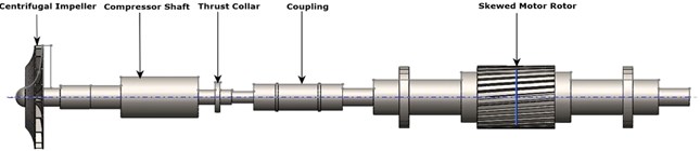
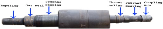
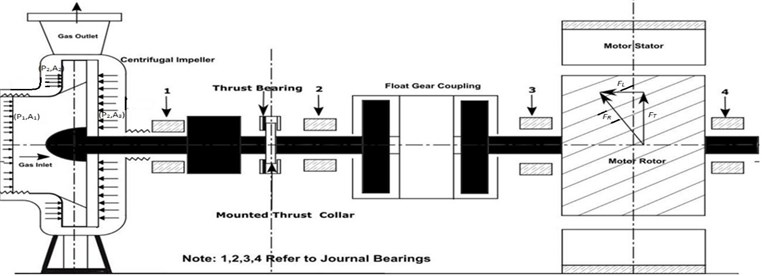
A single stage centrifugal gas compressor with volute casing coupled with squirrel cage induction motor is shown in Fig. 1. Gas compressor is coupled with induction motor drive of 2.5 MW power rating with 6.6 KV supply and three phase stator winding construction. This single stage centrifugal compressor handles H2S gas. The components mounted on the shaft are impeller, thrust collar and gear coupling hub. Both the driver and the driven shafts were coupled by float end gap gear coupling. The rotor system was supported radially on compressor side with two lobe journal bearings housed in compressor casing and similarly the motor rotor was supported with symmetrically plain sleeve bearings. The entire rotor system axially located by thrust bearing assembly has active and inactive sides constructed with tilting pad mechanism. The entire system installed on rigid foundation. These radial and thrust bearings supports the entire rotor. ISO VG 46 lube oil was supplied to the bearings to establish full film hydrodynamic lubrication in steady state operations. The compressor has a wet gas seal and seal balance was maintained by reference discharge gas.
Fig. 1Schematic diagram of turbo machinery coupled with cage induction motor
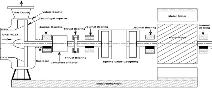
The sources for the thrust force generation in the compressor are discharge pressure in the impeller and axial force in the motor. The thrust bearing is under longitudinal force because of initial thrust force produced by run up of motor due to skewed bar rotor () and subsequently by the compressor while building the discharge pressure i.e. centrifugal impeller produced thrust. Both thrust forces produced by motor and impeller have same direction for a single stage compressor, which do not have balancing device. These axial forces are dynamic.
Fig. 2Skew slotted rotor with cage induction motor having symmetric air gap
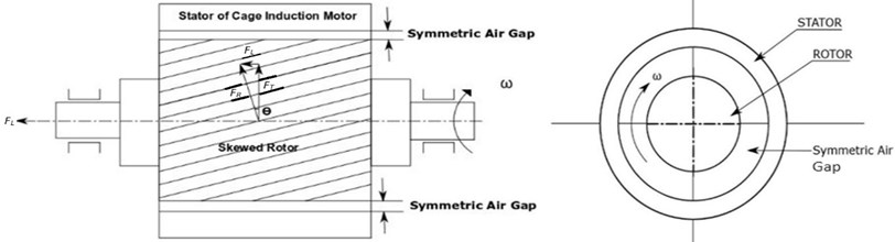
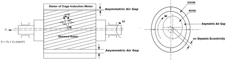
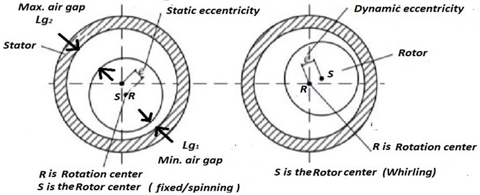
The induction motor coupled with turbomachinery has a skewed rotor slot. The skewness in rotor slots helps to avoid the cogging effect/locking tendency of the rotor during start-ups and continuity of rotor movements. This slotted skew effect produces longitudinal force component, (), as shown in Fig. 2. This constant force carries over to the thrust bearing as a thrust load as shown in Fig. 3(a), where skew slotted rotor has been installed asymmetrically in the stator which causes the dynamic eccentricity of the rotor which results in change of air gap permeability and subsequently changes in the twisting torque (). Further, changes in the twisting torque causes longitudinal vibrations in the thrust collar. Fig. 3(b) shows schematic diagram of two types of air gap eccentricities such as static and dynamic eccentricity. In static air gap eccentricity where the rotor centre () is fixed rotation centre at () spins. The minimum air gap () and maximum air gap () are shown in the Fig. 3(b). In dynamic eccentricity, the rotor centre () whirls/orbits around rotation center () due to flexible rotor stiffness. In the present study, the eccentric air gap in three phase induction motor considered it as static air gap eccentricity.
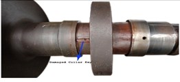
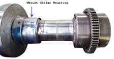
Fig. 4 shows the failure of thrust collar of a single stage gas compressor rotor assembly observed during the regular maintenance operations. The failure morphology shows the fretting wear of the thrust collar joint and key due to longitudinal vibrations. To understand the root cause of these thrust collar failures and longitudinal vibration amplitude, the regularly monitored operational vibration data was analyzed.
Fig. 3a) Skew slotted rotor with cage induction motor having asymmetric air gap, b) schematic diagram of static and dynamic air gap eccentricity in induction motor
a)
b)
Fig. 5 shows four bearing locations for overall vibration measurement indicated on turbomachinery locations with acceleration pickup. The measured overall vibration velocities (in rms values) on bearing housing in the vertical, horizontal, and longitudinal directions are given in Table 1. The chosen turbomachinery, as per ISO 10816-3 classification, referred under group I machinery with power rating between 300 KW and 50,000 KW installed on rigid foundation. For group I machines, vibrations are good up to 2.8 mm/sec rms velocity beyond which are restricted operation and for damage control.
From the Table 1 measurements, the motor bearing (locations 3 and 4) housing vibration amplitudes in longitudinal direction are more than 2.8 mm/s as prescribed by ISO 10816-3. These values show that the motor operations must be restricted for limited operations and corrective actions are required. Therefore, frequency analysis has been carried out and it was found that longitudinal vibrations are pre-dominant at synchronous sinusoidal force associated with rotating speed (1X harmonic) and further analysis performed to identify the source of excitation in the longitudinal vibrations by shaft vibration measurements.
The shaft longitudinal vibration measurements were done during steady state operations and transient run-up at thrust collar location using non-contact eddy current transducer. These longitudinal vibration transducers are like radial vibration measurement with eddy current vibration transducer and it works on Faraday’s inductive principle. The eddy current vibration transducer used in the measurement having 8 mV/μm sensitivity. This vibration spectral data to identify the critical speeds. The machine monitoring system used to measure shaft vibrations, axial displacement/thrust monitor, bearing metal temperatures and lube oil temperatures were installed as per API 670 standard. The shaft vibration limits are set according to API 617 [1] design code for centrifugal compressors. As per API 617 [1], allowable unfiltered vibration displacement limit at rated speed of 3000 rpm equals to 51 μm peak to peak. Similarly alarm and trip value for 3000 rpm is 71 μm peak to peak and 87 μm peak to peak, respectively. Overall unfiltered shaft longitudinal vibration measurements were found to be 71 μm (peak to peak) which is in the alarm zone. Fig. 6 shows the longitudinal vibration spectrum at thrust collar location for steady state operational speed of 3000 rpm. It is observed that 1X harmonic component is predominant.
Fig. 4Overview of turbomachinery rotor assembly and failure observations of thrust collar assembly for typical turbomachinery
a) Rotor motor coupled system
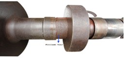
b) View 1: Damage thrust collar
c) View 2: Damage thrust collar
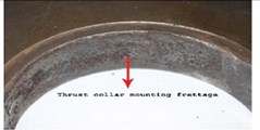
d) View 3: Frettage wear on thrust collar contact mounting surface
e) View of forged rotor shaft
f) Thrust collar locking sleeve
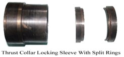
g) Thrust collar split locking rings
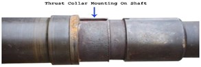
h) Thrust mounting surface on shaft
Table 1Overall vibration velocity measurements on turbomachinery bearing housing under steady state
Locations | Overall velocity vibrations on bearing surfaces in rms values and its harmonics | |||
Measurement points | Directional overall vibration velocity in mm/sec [rms] | Longitudinal vibration harmonics | ||
Vertical | Horizontal | Longitudinal | ||
1 | 1.5 | 1.9 | 1.3 | 1X harmonic is predominant |
2 | 1.4 | 1.8 | 1.4 | 1X harmonic is predominant |
3 | 3.4 | 4.8 | 4.3 | 1X harmonic is predominant |
4 | 3.3 | 4.8 | 4.2 | 1X harmonic is predominant |
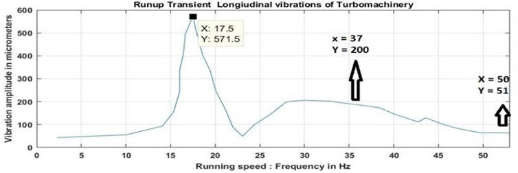
Fig. 7 shows the vibration spectrum at thrust collar location during machine run up and was seen to be having two critical speeds, which were two inertial equilibriums with preload stiffness of thrust bearing. The first critical speed was observed to be at 17.5 Hz due to the pre-load thrust from motor. The second critical speed is due to subsequent building of discharge pressure by single stage centrifugal compressor and it provided the additional preload to thrust bearing lube oil film and its centered frequency was identified to be 37 Hz with broad envelope. These critical speeds were observed during run-up of the turbomachinery and are a result of synchronous excitation caused by dynamic eccentricity due to asymmetric air gap in the induction motor. From the machine’s operation history, it was understood that the amplitude of the longitudinal vibrations was going up to alarm and trip levels during night hours when the temperature was not maintained. The lube oil, ISO VG 46, has a kinematic viscosity of 46 centistokes at 40 °C. The lubricant oil temperature drop causing increase in oil viscosity which in turn increases the hydrodynamic full film thrust bearing oil film stiffness which subsequently increases the natural frequency from 37.5 Hz and takes it towards the operation frequency of 50 Hz, there by amplifying the longitudinal vibrations to alarm and trip levels.
Fig. 5Schematic diagram showing vibration monitoring locations
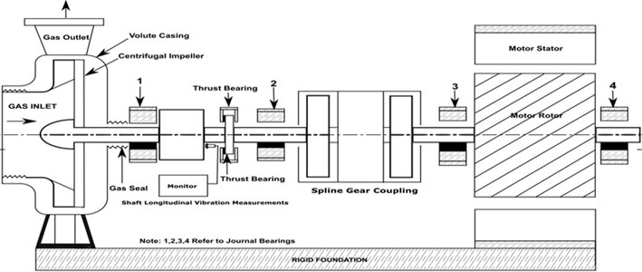
Fig. 6Vibration spectrum measured at thrust collar location longitudinal vibrations in steady state
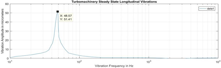
Fig. 7Vibration spectrum during transient run up longitudinal vibrations response as function of speed at measured thrust collar location
The high longitudinal vibrations in the cage induction motor are due to asymmetric air gap installations. These vibrations are micro level motions and caused the fretting wear between thrust collar and shaft mating contact surface, followed by secondary damages of the thrust collar assembly. The thrust collar being is an axial locating dynamic support of the entire rotor assembly which effects the primary mechanical safety of such Sour gas handling turbomachinery.
3. Analytical modelling and analysis
The experimentally observed critical frequencies and vibration response in longitudinal direction have been discussed in the previous section was predicted by the single degree of freedom (SDOF) tuned stiffness model. Primarily, the dynamic properties of the system such as two inertial equilibriums with mass (), tuned longitudinal stiffness of the rotor bearing system () and damping’s () were estimated and then the free and forced vibration analysis were performed.
Fig. 8SDOF model with tuned stiffness for turbo machinery coupled with induction motor longitudinal vibration response
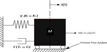
Fig. 8 shows the single degree freedom model of turbo machinery coupled with induction motor under longitudinal excitation. The entire rotor system including motor rotor, coupling and compressor shaft with impeller masses has been considered as lumped mass [], thrust bearing oil film with preloads were considered as longitudinal stiffness of the rotor bearing system [] from thrust preloads and the oil film damped property was taken as damping coefficient []. The chosen damping ratio for ISO VG 46 at 40°C is 0.1 for the current model. is longitudinal synchronous excitation harmonic force due to skewed rotor motor with static air gap eccentricity:
Critical frequencies of the system can be obtained by doing free vibration analysis. The mass of the rotor system and the initial thrust generated from motor remains constant and corresponding stiffness [] followed by increase in dynamic preloading of the compressor due to build up pressure in compressor during run- up and corresponding combined preload stiffness []. Therefore, was the first natural frequency that can be observed because of motor axial force pre-load of thrust bearing oil film whereas was the second natural frequency observed because of combined impeller thrust and the motor thrust preload. Hence, the critical frequencies of the rotor system can be written as:
where, is the preload stiffness from induction motor axial force:
where, is the total dynamic stiffness from combined thrust. For forced vibration model excited by longitudinal synchronous excitation harmonic force from skewed rotor motor at “1X” harmonic can be written as:
where, is the dynamic response of longitudinal vibration displacement in peak to peak and is given as:
where, and .
3.1. Calculation of longitudinal dynamic force
As shown in Fig. 2, the longitudinal force component () in Newton is a function of average load torque () in N-m, diameter of rotor () in meter and skew slotted rotor bar angle () in degrees:
This constant force carries over to the thrust bearing as a thrust load as shown in Fig. 3, where skew slotted rotor has been installed asymmetrically in the stator. This configuration causes the dynamic eccentricity of the rotor which in turn results in change of air gap permeability and the twisting torque (). The change in torque is proportional to the square of the current variation in a rotation of the motor rotor and causes variation in the phase load currents. Further, the dynamic eccentricity of rotor causes fluctuation of longitudinal force and it can be calculated as:
Total longitudinal force () is sum of fixed axial component force () and axial displacement harmonic force () for a fixed asymmetric air gap flux:
For induction motors at steady state [5, 6], the load torque () is equal to the product of square of the load current () and ratio of resistance and slip. In steady state, resistance of stator phase winding and slip are constant. Therefore, torque is proportional to the square of phase current:
where ‘’ is average torque (in Nm) and ‘’ is the load current (in Ampere). The change in the torque is proportional to square of the variations in the load current in a rotation.
and are the minimum and maximum ammeter readings of the phase load current of motor in steady state in Amperes:
The longitudinal dynamic force which is a sinusoidal harmonic force can be obtained by substituting the Eq. (10c) in Eq. (7b).
3.2. Total thrust force on bearing (
The total thrust force on the bearing is sum of total longitudinal forces () and thrust from compressor impeller and it is given as:
where, and are the suction and discharge pressures of the single stage gas compressor as shown in Fig. 9; is suction opening of impeller area; is the impeller hub area and is the shroud areas.
Fig. 9Thrust estimation of turbo machinery coupled with cage induction motor
3.3. Estimation of longitudinal dynamics parameters for turbomachinery:
One of the dynamic parameters is the longitudinal stiffness which is effectively governed by thrust bearing hydrodynamic lube oil film stiffness. The rotor stiffness () is very high when compared to stiffness of lube oil film () and they are in series in axial direction. Therefore, the effective stiffness of the system is dominated by the oil film stiffness. This stiffness is proportional to the preload acting on tilting pad thrust bearing and can be written as:
where, is the total thrust force and is the axial displacement. (54991 N) was directly estimated from total thrust calculations and (431.8 μm) was read from the thrust monitor of turbomachinery.
Similarly, is the dynamic stiffness and is proportional to the pre-load from motor thrust force (). By assuming the linear behavior of the dynamic stiffness as a function of pre-load and can be related as:
The mass of entire rotor can be estimated using density of the material (low alloy steel density having 7850 Kg/m3). In this study, the mass of rotor was approximated to 2413 kg. Typical stiffness and damping properties of hydrodynamic tilting pad bearing were 131000 N/mm and damping ratio of 0.1 according to API 684 standard. The stiffness arrived from total thrust () and thrust monitor deflection ( is 1,36,008 N/mm using Eq. (12) and using damping ratio (0.1) for ISO VG 46, the damping () is 112.45 N-s/mm. Both API 684 and Measured and C are comparable.
Dynamic viscosity () of lube oil is proportional to viscous shear force () as per Newton’s law of viscosity when speed and thrust bearing geometry is constant. Similarly, for full film lubrication, as per law of friction, viscous shear force () is proportional to preload of thrust bearing (). The full lubricant film stiffness () is proportional to dynamic viscosity:
From Ref. [7], empirical formulation of static air gap for induction motors at high speeds (≥ 3000 rpm) to avoid excessive iron loss is given in Eq. (15). This equation is a function of power (). The calculated nominal air gaps () from empirical equation for choosing induction motors are in line with the measured air gap lengths:
4. Results and discussion
The measured steady state and trainset vibration response of machine 1 in longitudinal direction is shown in Figs. 6 and 7. The steady state longitudinal shaft dynamic spectral response vibrations at thrust collar location is 51.41 μm peak to peak at 48.57 Hz. It is observed that the dominance of synchronous harmonic (1X) response in longitudinal vibration spectrum. Hence, it is inferring to static air gap eccentricity. Similarly, Fig. 7, indicating the transient vibrations spectral response during run up. It is observed that first resonance at 17.5 Hz and corresponding frequency response is 571.5 μm and second resonance at 37 Hz and corresponding frequency response is 200 μm peak to peak. The first resonance is associated with motor thrust and is modeled as dynamic stiffness. At this stage pressure was not built in the compressor. As the operating speed increases the differential pressure across the impeller increases which can be modeled as variable stiffness.
Table 2 gives the dimensions and measured parameters of chosen machine configuration in terms of geometry, gas pressures, electrodynamics, air gap lengths and including lubricant damping ratio for Machine 1. The machine 1 details in the Table 2 are used for analytical study and comparison of response. Table 3 shows the calculated parameters and vibration response from the proposed analytical formulation. The steady state longitudinal vibration response was evaluated using Eqs. (5 and 6). and was found to be 51 μm and the measured value (51.4 µm). The other machines (2, 3 and 4) have geometrically similar construction and same longitudinal dynamic characteristics such as stiffness (), mass of the rotor () and viscous damping of oil film () including power rating. Table 4 shows the vibration displacements of four similar turbomachinery which have different static air gap eccentricity values with integrated measurements. This static air gap eccentricity created the variation in the phase currents of the motor and dynamic force. Analytical results are in good agreement with experimental results. Similarly, critical frequencies were evaluated for two different inertial equilibriums with preloaded dynamic stiffness using Eqs. (2 and 3). The first critical speed () varied from 18 Hz and the second critical speed () from 37.78 Hz. The natural frequencies obtained from the analytical model matches with the experimentally measured critical speeds 17.5 Hz and 37 Hz.
Table 2Machine 1 geometry and operating conditions data
Operating parameter | Units | Measured values |
– average load torque | Nm | 7003 |
– skewed rotor diameter | m | 0.32 |
– skew slot angle of cage rotor | In degrees | 16° |
– gas inlet gauge pressure of compressor | bar | 17.652 to 18.633 |
– gas outlet gauge pressure of compressor | bar | 20.103 to 21.084 |
– area of impeller suction [diameter is 649 mm] | mm2 | 330810 |
– area of the impeller shroud [outer diameter is 900 mm, inner diameter 649 mm] | mm2 | 305362 |
– area of impeller hub [outer diameter is 900 mm and shaft diameter are 154 mm] | mm2 | 617546 |
– minimum phase current of motor on load | Amperes | 200 |
– phase current total variation | Amperes | 224 |
– static deflection at thrust monitor | μm | 431.8 |
ISO VG 46 lubricant damping ratio | ratio | 0.1 |
– length of the air gap | mm | 3.824 |
Static air gap eccentricity | mm | 0.41 |
– minimum air gap length (static) | mm | 3.414 |
– maximum air gap length (static) | mm | 4.234 |
Table 3Machine 1 geometry and operating conditions data
Parameter | Calculated value |
Fluctuating torque (refer Eq. (10)) | 3086 Nm |
Fluctuating axial load on the bearing (refer Eq. (7b)) | 5531 N |
Total thrust () on the bearing (refer Eq. (11)) | 56187.8 N to 54360.5 N |
Average total thrust | 55274.2 N |
The component of compressor thrust () | 43,636.8 N to 41809.5 N |
Average compressor thrust | 42724 N |
Total longitudinal dynamic stiffness of the oil film () | 1,36,009.3 N/mm |
Stiffness of oil film (), produced due to preload thrust from motor | 30,882 N/mm |
Steady state longitudinal vibration response (Refer Eqs. (5-6)) | 51 μm |
From calculated dynamic response parameters, the steady state vibration displacement at 1X is estimated using Eqs. (5-6) and was found to be 51 μm for the chosen configuration and the experimentally measured value was 51.4 µm. Thus, shows the analytical and experimental results are in good agreement. Thereby, the proposed analytical model was verified with similar configuration data of turbomachinery.
Based on the experimental observations, the lubricant low temperatures are the cause for increasing the vibration response and it leads to machine vibration protection trips. The same was studied by parametric study and verified with analytical model. Table 5 shows the ISO VG 46 lube oil properties as a function of temperature and stiffness calculation and the predicted vibration response of Machine 1 in longitudinal direction as function of temperature. The machine 1 is rotating at 3000 rpm. In this study, the thrust bearing lube oil film stiffness varies with respect to temperature changes has been estimated using Eq. (14). The predicted vibration response at 1X in longitudinal direction of machine 1 at 40 °C indicated in Table 5 and is matching with measured vibration data as mentioned in Table 4. The vibration response increases as the lubricant temperature decreases because of the critical speed is shifting towards the operating speed which causes response amplification.
The calculated longitudinal vibration response using simple analytical model and measured values are in good agreement for the chosen configurations.
Table 4Measurement parameters and longitudinal vibration displacement of various compressors
Compressors | Measurements and geometry parameters | Vibration displacement (µm in peak to peak) | |||||||||
(N-m) | (m) | Nominal air gap (mm) | Static air gap eccentricity (mm) | (Amp) | (Amp) | (N-m) | (N) | Calculated [1X] | Measured [1X] | ||
1 | 7003 | 0.32 | 16° | 3.824 | 0.41 | 200 | 224 | 3086 | 5531 | 51 | 51.4 |
2 | 7003 | 0.32 | 16° | 3.824 | 0.30 | 210 | 228 | 2169 | 3887 | 35.1 | 37 |
3 | 7003 | 0.32 | 16° | 3.824 | 0.26 | 212 | 228 | 1890 | 3387 | 30.8 | 32 |
4 | 7003 | 0.32 | 16° | 3.824 | 0.20 | 210 | 222 | 1426 | 2556 | 23.1 | 24 |
Table 5Dynamic stiffness variation of thrust bearing oil film with change in viscosity
ISO VG 46 | Dynamic viscosity, (cP) | Thrust preload, (N) | Lube oil film stiffness () (N/mm) | Second critical speed () (Hz) | Longitudinal vibration response (μm peak-peak) |
At 40 °C | 43 | 5531 | 136008 | 37.7 | 51 |
At 35 °C | 60 | 5531 | 189779 | 44.6 | 85.8 |
At 30 °C | 78 | 5531 | 246712 | 50.9 | 112.3 |
5. Conclusions
The present paper has discussed the effects of longitudinal vibrations on tilting pad bearing in a turbomachinery coupled with squirrel cage induction motors with skew slotted bar rotor. Thrust bearing failures such as fretting wear and looseness of thrust collar assembly was observed in regular maintenance activities. Severe longitudinal vibration values were recorded during operations. The longitudinal vibrations were due to static air gap eccentricity of the rotor which causes thrust collar damages. A simple analytical formulation has been developed to calculate the longitudinal vibrations. Fluctuating longitudinal load is estimated from the fluctuating motor torque which is proportional to variation in square of the measured phase current of the motor. The predicted analytical results are in good agreement with experimental measurements. Similar observations were made for other compressors having the same load rating, speed and dynamic parameters identified with different static air gap eccentricities. Where steady state response vibration spectrum clearly indicating synchronous harmonic response infers the machines are having static eccentric air gaps. The key indicators in determining the longitudinal vibration response are rotor motor skewness, air gap static eccentricity and variation in electrodynamic current, thrust bearing hydrodynamics stiffness and temperature of the lubricant (ISO VG 46).
During run-up of the gas compressor spectrum shows that two critical speeds are the result of pre-load stiffness of thrust bearing lube oil film. Particularly, second critical speed response envelope changes during steady-state operations, when the lube oil temperature changes with respect to viscosity of the oil film which in turn increases the stiffness. The evaluated longitudinal vibration response using simple analytical model and measured values are in good agreement.
References
-
API Standard 617. Centrifugal Compressors for General Refinery Service, Fifth edition, 1988.
-
API Publication 684. An Introduction to Lateral Critical and Torsional Analysis and Rotor Balancing, First edition, 1996.
-
GunterEdgar J. Lund’s contribution to rotor stability: the indispensable fundamental basis of modern compressor design. Journal of Vibration and Acoustics, Vol. 125, 2003, p. 462-470.
-
Young T. H., Shiau T. S., Kuo Z. H. Dynamic stability of rotor-bearing systems subjected to random axial forces. Journal of Sound and Vibration, Vol. 305, Issue 22, 2007, p. 467-480.
-
Bradford C. E., Rhudy R. G. Axial magnetic forces on induction motor rotors. Journal of AIEE Transactions, Vol. 72, 1953, p. 488-492.
-
Subrahmanyam V. Axial magnetic forces in induction motors with skewed slots. Proceedings of the Institution of Electrical Engineers, Vol. 122, 1975, p. 149-153.
-
Phyhonen Juha, Jokinen Tapani, Hrabovacova Valeria, Niemela Henna Design of Rotating Eletrical Machines. John Wiley and Sons Ltd, 2008.
-
Kometani H., Sakabe S., Nakanishi K. 3-D electro-magnetic analyses of a cage induction motor with rotor skew. IEEE Transactions on Energy Conversion, Vol. 11, Issue 2, 1996, p. 331-337.
-
K.C. Agrawal Industrial Power Engineering and Applications Handbook. 1st edition, Butterworth Heineman, 2001.
-
Thomson W. T. Philip Current and vibration monitoring for analysis of induction motors. Proceedings of the 31st Turbomachinery Symposium, 2002.
-
Thomson W. T., Gilmore R. Motor current signature analysis in induction motor drives. Proceedings of 32nd Turbomachinery Symposium, 2003.
-
Costello M. J. Understanding the vibration forces in induction motors. Proceedings of the 19th Turbomachinery Symposium, 1990.
-
Narendra S. M. Comprehensive analysis rotor eccentric fault in squirrel cage induction motor. International Journal of Scientific Research and Development, Vol. 7, Issue 3, 2019, p. 1659-1666.
-
Tenhunen A., Benedetti T., Holopainen T. P., Arkkio A. Electromagnetic forces in cage induction motors with rotor eccentricity. IEEE International Electric Machines and Drives Conference, 2003.
-
Zeidan F. Y., Herbage B. S. Fluid film bearing fundamentals and failure analysis. Proceedings of the 20th Turbomachinery Symposium, 1991.
-
Zeidan F. Y., Paquette D. J. Application of high speed and high performance fluid film bearings in rotating machinery. Proceedings of the 23rd Turbomachinery Symposium, 1994.
-
Guo A., Wang X., Jin J., Hua D. Y., Hua Z. Experimental test of static and dynamic characteristics of tilting-pad thrust bearings. Advances in Mechanical Engineering, Vol. 7, Issue 7, 2015, p. 1-8.
-
Srikanth D. V., Chaturvedi K. K., Reddy A. C. Modelling of large tilting pad thrust bearing stiffness and damping coefficients. Tribology in Industry, Vol. 31, Issues 3-4, 2009, p. 23-28.
-
Baldassarre L., Bernocchi A., Rizzo E., Fontana M., Maiuolo F. Axial thrust in high pressure centrifugal compressors: description of a calculation model validated by experimental data from full load test. 44th Turbomachinery and 31st Pump User Symposia, 2015.
-
Childs D. W., Delgado A. Tilting-pad bearings: measured frequency characteristics of their rotordynamic coefficients. Proceedings of the 40th Turbomachinery Symposium, 2011.
-
Zhao Lucy Yu Axial vibration for a sychronous motor with gear box compressor train. 42nd Turbomachinery and 29th Pump Symposium, 2013.
-
Zhang G., Zhao Y., Li T., Zhu X. Propeller excitation of longitudinal vibration characteristics of marine propulsion shafting system. Shock and Vibration, Vol. 2014, 2014, p. 413592.
-
Huang Q., Yan X., Wang Y., Zhang C., Jin Y. Numerical and experimental analysis of coupled transverse and longitudinal vibration of a marine propulsion shaft. Journal of Mechanical Science and Technology, Vol. 30, 2016, p. 5405-5412.
-
Krishnareddy G., Venkatesham B., Ramireddy G. Vibration diagnosis of turbomachinery coupled with the induction motor. Vibroengineering Procedia, Vol. 35, 2020, p. 1-6.
About this article

