Abstract
The autocorrelation function is combined with wavelet transform and cyclostationary theory (WT-AF-CT) in place of threshold denoising, and meanwhile the mean power ratio (MPR) is calculated by the proposed method. Furthermore, extracted characteristic as well as calculated MPR is used to identify compound faults of rolling bearings in aero-engine based on casing vibration acceleration signal-including the ones of common rolling bearing (inner race rotates and outer race is constant) and intershaft bearing (co-rotates with outer and inner race). A comparative analysis was carried out between conventional researches (cyclostationary theory (CT) or wavelet transform combined with threshold value denoising (WT-TD)) and proposed WT-AF-CT method. Additionally, the effect of sensors installation direction for feature separation and extraction of compound faults is considered. The results indicate that the proposed WT-AF-CT method can separate and extract characteristics of compound faults exactly and identify fault types of bearings precisely, no matter sensors are installed horizontally or vertically, while CT or WT cannot.
1. Introduction
The fault modes of rolling bearing are usually compound in real aero-engines due to the intercoupling among faults [1, 2]. On the contrary, more researches have been mainly concentrated on single fault rather than compound ones at present [3, 4]. The faults of rolling bearing would result in increased vibration and even lead to a flameout during flight because the rotor is locked, which would cause tremendous threat and damage to aero-engine [5, 6]. Therefore, it is crucial and essential to monitor the working conditions and identify the fault types of rolling bearings. The intershaft bearing, which co-rotates with outer race and inner race, is widely used in aero-engine at present [5]. The faults of intershaft bearing are probably frequent due to high operating temperature, insufficient lubrication and large dynamic load, etc. In 2007, Hu, et al. analyzed the co-rotating and counter rotating between inner and outer race of cylindrical intershaft bearing in aero-engine by quasi static method [7]. Liao, et al. designed an intershaft bearing experiment rig according to kinetic and structural features of dual-rotor turbofan engine [8].
Rotate mode and symmetric or closely symmetric physical structure provides vibration signal of aero-engine with cyclostationary feature. Therefore, the condition monitoring and fault diagnosis in bearings of aero-engine can be studied in cyclostationary theoretical frame [9, 10]. On the one hand, cyclostationary theory reflects signal statistics varying with time and offsets the deficiency in the processing of cyclostationary signals; on the other hand, periodic changes of signal statistics are taken to simplify the treatment of normal non-stationary signals. The most representative study of cyclostationary theory is from J. Antoni [9, 11, 12]. Luo et al. used second-order directional cyclostationarity to analyze complex signals from journal bearing which supports a rotor system operating with oil whip [13]. Based on chirplet path pursuit and order cyclostationary demodulation, Xu., et al. proposed a diagnosis method of roller bearing in 2013 [14]. In considering that fact that the effect of bearing fault diagnosis with maximum second order cyclostationary blind deconvolution (CYCBD) depends on the precision of characteristic frequency of choice and the length of filter, Huang Baoyu, et al. implemented fault diagnosis of bearings by proposing the method which optimizes CYCBD with Cuckoo search algorithm (CSA) and treats Improved maximum harmonic significance index (IHSI) as the basis of optimization [16]. Wu Bin, et al. proposed the calculation method for order ratio cyclostationary autocorrelation function, combined the demodulation function of cyclostationary analysis to vibration signals and continuous hidden Markov model (CHMM), and thereby proposed a fault diagnosis method for rolling bearings applicable to the operation with variable speed, and then verified the feasibility of method [17].
Wavelet transform is widely applied to identify fault weak and compound of bearings due to its time-frequency localization characteristics [15, 18-20]. For example, Shen Zhengwei, et al. proposed a wavelet construction method based on fractional order and carried out the extraction of characteristics of bearing faults [21]. Liao Chuanjun, et al. analyzed the signal characteristics of acoustic emission (AE) and firstly proposed the analysis method of wavelet redistribution scale spectrum based on AE signals according to the extraction principles of fault characteristics of AE signals and features as a result of mechanical faults or injury, and then applied the method to the identification of injury type and parts of rolling bearings in acoustic emission inspection [22].
The applied studies of bearings have been improved by scholar studies, domestic and overseas. However, these studies, including CT and WT-TD, are mostly concentrated on the signals from bearing block rather than casing signals, and a single fault than compound faults [3-6, 20]. Signal distortion, energy attenuation and noise effect make casing signal much more complex and weaker than the signal of bearing block, which is a kind of comprehensive and complicated response from many parts of aero-engine. Additionally, feature extraction of compound faults is far more difficult than that of single fault [3, 4]. That is, no matter traditional studies focus on the signals from bearing block or single fault, they will result in an extremely large gap between theoretical study and practical engineering application, which adds to the difficulty of bearing fault diagnosis in aero-engine.
Considering approximately symmetric physical structure and rotation way of aero-engine, the analysis of vibration signals of casing within the framework of cyclostationary theory can produce more precise status monitoring and fault identification of bearings. Autocorrelation function can maintain the periodicity of signal and reduce noise, and convert frequency modulation (FM) signal which usually exists in fault signal of bearing to amplitude modulation (AM) signal [10]. From the above, the autocorrelation function is introduced to wavelet transform and combined with cyclostationary theory (WT-AF-CT) for separating and extracting the characteristic of compound faults of rolling bearing-including the ones of intershaft bearings and normal rolling bearings. Meanwhile, to identify the fault types of rolling bearing in more visual and simpler manners, the MPR is calculated by proposed WT-AF-CT method. The comparison analysis is implemented among CT, WT-TD and WT-AF-CT. Finally, the effect of installation direction of sensors on feature separation and extraction is considered.
2. WT-AF-CT method
2.1. Wavelet transforms (WT)
Due to good local nature of wavelet transform, the frequency resolution is higher in low frequency and time resolution higher in high frequency. This just fits the nature of low frequency signals (slow change) and high frequency signals (fast change). Therefore, it is feasible to combine wavelet transform and cyclostationary theory to extract characteristics of compound faults and identify a fault type.
Suppose is a continuous signal, and then wavelet transform is defined as the integral of product of signal and basic wavelet function :
The scaling function is as follow:
where is the scale factor, and is the translation factor.
Then by the DWT (discrete wavelet transform) the wavelet coefficients of the signal can be defined by the following equations:
where is a scale two-level decomposition function of discrete wavelet transform; is the position decomposition function of discrete wavelet transform.
2.2. Autocorrelation function (AF)
As the vibration signals of aero-engine are typical cyclostationary, they usually include modulation components when a bearing fault happens. For that, we can go through cyclic autocorrelation function analysis and take the slices of function under some cyclic frequencies for absolute value demodulation to solve modulation frequency of signals, and then implement the characteristic extraction and fault identification of compound faults.
Assuming one signal decomposed by wavelet transform is , and is introduced to obtain, and t represents time, is length of:
Defined autocorrelation function and then represents the cycle-autocorrelation function of when cycle frequency is equal to .
Given one amplitude-modulated signal :
/ respectively keeps the amplitude of carrier signal and modulating signal. , remains respectively the frequency of carrier and modulation signal, so we can also conclude:
We can have Eq. (9) according to Eqs. (7-8):
It is very clear that cyclic-autocorrelation function is not equal to zero when and only when cycle frequency , , , , and . Suppose is selected and not equal to zero (represents stationary signal), the slice signal of cycle-autocorrelation function is analyzed by given value. Additionally, the fault characteristics can be separated and extracted by obtaining frequency spectrum of slice signal.
2.3. Characteristic frequency of bearings
Considering the one-to-one correspondence relationship between a fault type and characteristic frequency of bearings, the extracted feature frequency can be used to monitor running status and identify the fault type of bearings [5,6]. Supposing pitch diameter is, rolling elements diameter and number is respectively and , and contact angle is equal to zero. Rotating speed of outer race and inner race is respectively and . If outer and inner race rotates in the same direction, the sign of and is the same, otherwise, opposite. If outer or inner race is constant, then corresponding or is equal to zero. is the absolute difference of rotational speed between inner and outer race of bearings. The characteristic frequency of bearings can be expressed as follows:
Characteristic frequency of inner ring:
Outer ring :
Rolling body :
Characteristic frequency of holder and outer ring in rubbing:
Characteristic frequency of holder and inner ring in rubbing:
2.4. Mean power ratio (MPR)
A vibration signal, , and its Fourier transform, , is defined, then the mean square value which is mean power of such that:
where represents the length of . Supposing a frequency band is given, then the mean power of the selected frequency band can be calculated according to Eq. (17). Meanwhile, the MPR of selected different frequency bands can be shown as follows:
where , , , respectively represents the starting point and end point of selected different frequency band of , and is MPR of selected different frequency bands.
3. Compound faults characteristic separation and extraction
When a fault occurs in bearings, the amplitude of vibration signal will be modulated by characteristic frequency which matches the failure type of bearings. That is, to monitor the running state of bearing and identify the type of fault, the in Eq. (9) can be valued according to the characteristic frequency obtained by Eqs. (10-14) or the double. Considering that the fault characteristic of bearings, in casing response, is weak and complex, cyclic statistic alone probably cannot identify the compound faults. Based on above consideration, a new method of WT-AF-CT is proposed and the corresponding MPR is calculated according to Eqs. (9-16) in order to separate and extract the characteristics of compound faults of bearings. Meanwhile the comparison analysis is carried out in conventional method (CT and WT-TD) and WT-AF-CT. Specifically, the conventional research is shown in Fig. 1(a), and proposed WT-AF-CT method is shown in Fig. 1(b).
Specific process of each scheme is as follow:
(1) In Fig. 1(a), the concrete steps of characteristic extraction based on CT and WT-TD are as follow:
1) CT method: for vibration signals from bearing block, directly make slick analysis with cyclic autocorrelation function within the framework of cyclostationary theory and extract fault characteristics based on the frequency spectrum of slice signals.
2) WT-TD method: combine wavelet transform and threshold value denoising to carry out characteristic extraction and fault identification. Firstly, separate vibration signals of bearing block with wavelet transform; secondly, denoise approximate signals and detail signals as a result of wavelet decomposition based on wavelet threshold value denoising; finally, choose the frequency spectrum of approximate signals or detail signals of good extraction effect for characteristic extraction and identification of fault.
(2) In Fig. 1(b), specific steps of characteristic extraction with the proposed WT-AF-CT method are as follow:
Firstly, subject vibration signals of casing to time-frequency local decomposition based on wavelet transform; secondly, characteristic enhancement and denoising of detail signals and approximate signals after wavelet transform with autocorrelation function; thirdly, detail signals or approximate signals of better characteristic extraction effect are given slice analysis based on cyclic autocorrelation function; fourthly, calculate the frequency spectrum of slice signals. Meanwhile, for more intuitive analysis and judgment, we have calculated the average power of each characteristic frequency spot according to Eqs. (15-16). At last, based on average power and frequency spectrum of slice signals, extract characteristics of compound faults of bearings and identify a fault type.
Fig. 1researches scheme for a) traditional research and b) proposed WT-AF-CT method
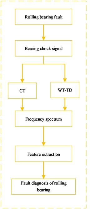
a)
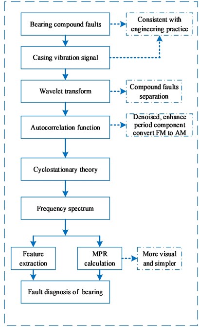
b)
The special corresponding relationship among different schemes and methods is shown in Table 1.
Table 1the corresponding relationship among different scheme and method
Traditional research | Proposed new method | ||
Scheme A | Scheme B | Scheme C | Scheme D |
CT alone | WT-TD | WT-AF-CT | MPR basis for WT-AF-CT |
4. Compound faults of intershaft bearing
Limited by the space, the compound faults of intershaft bearing are analyzed. The dynamical model of one birotor aero-engine is shown in Fig. 2. The vibration acceleration sensors are installed vertically and horizontally on the rear casing in aero-engine. Inner and outer race of intershaft bearing rotates in the same direction and the sample frequency is 16384 Hz. In the stage of test running of the aero-engine, the standard value of the slide oil spectrum overstepped restricted value, and meanwhile the monitored vibration value of high-pressure-rotor was increasing with rotational speed-including horizontal and vertical direction of rear casing, which proves to be inconsistent with the previous test running of the model aero-engine. To seek for a fault cause, casing vibration acceleration signal is analyzed. The specific geometry parameter of intershaft bearing is shown in Table 2. The , , , , and .
Fig. 2Rotor supporting dynamical model of one birotor aero-engine
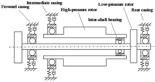
Table 2the geometric parameter of intershaft bearing
Rolling elements diameter | Rolling elements numbers | Pitch diameter | Inner race radius | Outer race radius |
18.06 mm | 28 | 212.76 mm | 97.35 mm | 115.41 mm |
4.1. Case study
4.1.1. Cyclostationary theory-scheme A
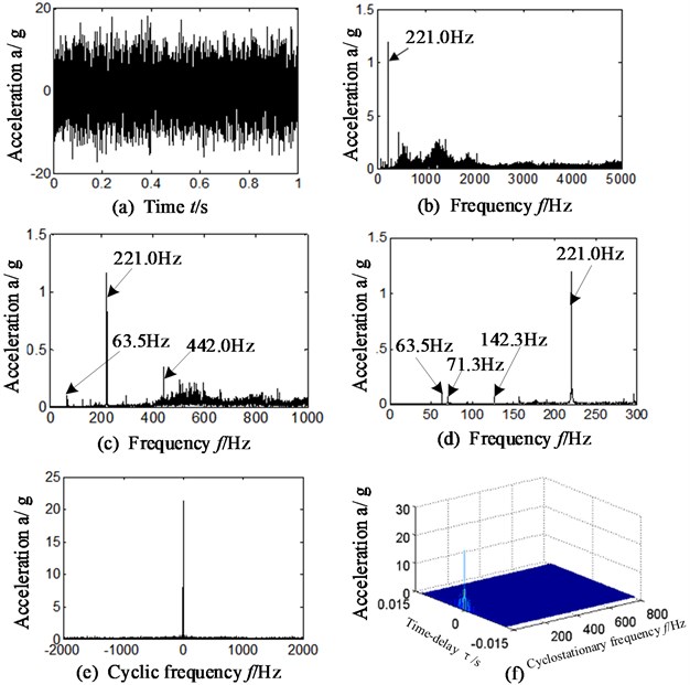
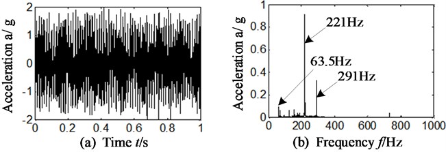
To separate and extract the compound fault characteristics of intershaft bearing, the slice signal of cyclic autocorrelation function, on different cyclic frequency positions, is analyzed. The rotational speed of high-pressure and low-pressure rotor is respectively 13260 r/min and 3810 r/min, and the corresponding rotational frequency proves respectively 221 Hz (13260/60) and 63.5 Hz (3810/60), respectively. The feature frequency of inner race, outer race and rolling element of intershaft bearing is respectively equal to 2562.2 Hz, 2162.8 Hz and 924.8 Hz by calculation according to table.2 and Eqs. (10-12). The feature frequency of retainer rubbing outer race and retainer rubbing inner race is respectively 72.1 Hz, 85.4 Hz by calculation according to Table 2 and Eqs. (13-14). Limited by space, the vibration acceleration signal of horizontal direction is analyzed firstly. The results are displayed in Fig. 3. The Fig. 3(a) is the time-domain of original casing vibration acceleration signal. The Fig. 3(b)-(d) is frequency spectrum and its local amplification. Fig. 3(e) is the slice signal of cyclic autocorrelation when time-delay is equal to zero. Fig. 3(f) represents three-dimensional slice graph of cyclic autocorrelation, and \\ axis is respectively cyclic frequency\time delay\vibration amplitude.
Analyzing Fig. 3, the following conclusions can be drawn:
(1) There exists obvious rotational frequency (221.0 Hz) and its double frequency (442.0 Hz) of high-pressure rotor in Fig. 3(b)-(d); meanwhile, there is weak rotational frequency of low-pressure rotor (63.5 Hz).
(2) By further analysis, the weak frequency component 71.3 Hz and 142.3 Hz can be observed in Fig. 3(d). These 2 frequency components are approximately equal to the feature frequency of outer race rubbing against retainer of intershaft bearing (72.1 Hz) and its double. However, compared with other frequency components in the spectrum, these characteristics are very weak.
(3) In the analysis of Fig. 3(e)-(f), it can be observed that no matter in slice signal or three-dimensional slice graph of cyclic autocorrelation function, there is no obvious feature frequency of intershaft bearing.
Namely, cyclic autocorrelation function alone cannot separate and extract the characteristic frequency and identify the compound fault types of intershaft bearing because of the weakness and complexity of fault characteristic in casing response of aero-engine.
Fig. 3a) time-domain signal, b)-d) frequency spectrum, e) slice signal, f) three-dimensional slice graph
4.1.2. Wavelet transform is combined with threshold denoising-scheme B
Wavelet transform is used to extract the features of compound faults of intershaft bearing, and the data selected is the same with section 4.1.1 and the results are shown in Fig. 4. Considering sym N-series of wavelets are featured by orthogonality, compactness and approximate symmetry, sym6 wavelets are selected to actualize signal separation and the number of decomposition layers is 5. The unified-threshold denoising method is selected. Fig. 4(a) is the approximate signal a5 (the optimal is selected) after denoising and Fig. 4(b) is the frequency spectrum of Fig. 4(a).
In Fig. 4(b), there exists obvious frequency 221.0 Hz and 63.5 Hz, which respectively matches the rotational frequency of high-pressure and low-pressure rotor. Meanwhile, there exists the frequency component 291 Hz, and it is exactly equal to the sum of rotational frequency (221 Hz) of high-pressure rotor and feature frequency (72.1 Hz) of retainer rubbing outer race (221+72.1 = 293.1 Hz 291). It can identify the fault of outer race rubbing retainer in intershaft bearing, while the feature frequency of inner race rubbing retainer cannot be observed.
Fig. 4Approximate signal a5 and its frequency spectrum
4.2. WT-AF-CY: proposed new method-shown in Fig. 1(b)
To separate and extract the characteristic frequency of compound faults, and meanwhile identify and judge the fault types of inter-shaft bearing precisely, the autocorrelation function is introduced to wavelet transform and combined with cyclostationary theory. For a comparison, the data, wavelet function (sym6) and selected decomposing level (5) is the same with section 3.1. The specific steps of proposed method are shown in Fig. 1(b) marked by blue. The results are displayed on Fig. 5.
Fig. 5a)-b) time-delay slice signal, c)-f) three-dimensional slice graphs: approximate signal a5 based on WT-AF-CY method
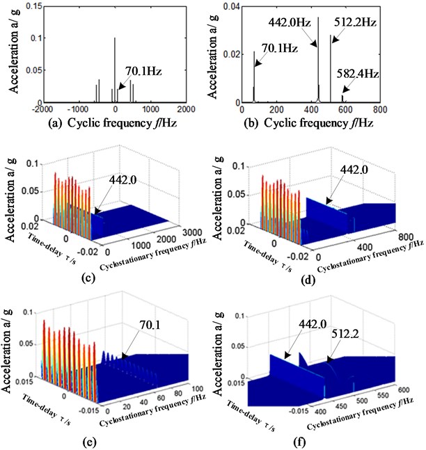
Fig. 5(a)-(b) is the slice signal of cyclic autocorrelation function which corresponds with autocorrelation function of reconstructed approximate signal a5. Fig. 5(c)-(f) represents three-dimensional slice graphs and its local amplification by proposed WT-AF-CY method, and \\ axis respectively represents cyclic frequency, time delay signal and vibration amplitude. Fig. 5(a)-(b) is respectively corresponding with cyclic frequency –2000 Hz~2000 Hz and 0 Hz~800 Hz. Fig. 6(c)-(f) is respectively corresponding with cyclic frequency 0 Hz~3000 Hz, 0 Hz~800 Hz, 0 Hz ~100 Hz and 600 Hz~800 Hz.
By precisely analyzing Fig. 5, the following conclusions can be drawn:
In Fig. 5(a)-(f), no matter in the time-delay slice signals or in three-dimensional slice graphs based on proposed WT-AF-CY method, it can be observed that there is outstanding frequency 70.1 Hz, which is approximately equal to the feature frequency of retainer rubbing against outer race. After further analysis of Fig. 5(a)-(f), the outstanding frequency 512.2 Hz can be found, which just matches the 6-multiplication frequency of retainer rubbing inner race (85.4 Hz) of intershaft bearing.
It can be concluded that the intershaft bearing of aero-engine has faults, and the fault types are supposed to include retainer rubbing inner race and retainer rubbing outer race. Further studies are implemented in order to verify the correctness of analysis based on proposed WT-AF-CY method, and the frequency spectrum of slice signal is shown in Fig. 6. Fig. 6(a)-(d) is respectively matching with time-delay slice signal and their frequency spectrum, and the slice positions are corresponding with cyclic frequency equal to retainer rubbing outer race feature frequency and its double (the result is similar if we select cyclic frequency equals to retainer rubbing inner race feature frequency or twice).
Fig. 6a)-d) Time-delay slice signal and their frequency spectrum – approximate signal a5: for a), c) cyclic frequency equal to foc, for b), d) cyclic frequency equal to 2foc
Analyzing Fig. 6(a) and (c), there exists outstanding frequency 255.6 Hz which is just corresponding with triple frequency of feature frequency of retainer rubbing inner race (85.4 Hz). Meanwhile, in Fig. 6(b) and (d), there is the frequency 143.0 Hz that matches with double frequency of feature frequency of retainer rubbing outer race (72.1 Hz).
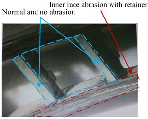
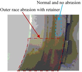
Namely, the intershaft bearing may have the compound faults of inner race rubbing against retainer and outer race rubbing against retainer. To further prove the accuracy of analysis, we disassembled the aero-engine and the picture of intershaft bearing is as shown in Fig. 7.
By carefully observing Fig. 7, it can be found that there is abrasion trace founded in the retainer with inner race and outer race of intershaft bearing. It is consistent with the results according to single-channel casing vibration acceleration signal based on proposed WT-AF-CY method. That is, the compound faults characteristic can be separated and extracted; moreover, compound fault types of intershaft bearing of aero-engine can be identified correctly and effectively based on proposed WT-AF-CY method, while the traditional research-including CT and WT-TD cannot.
Fig. 7Abrasion diagram of intershaft bearing
a)
b)
4.3. The effect of sensor installed direction
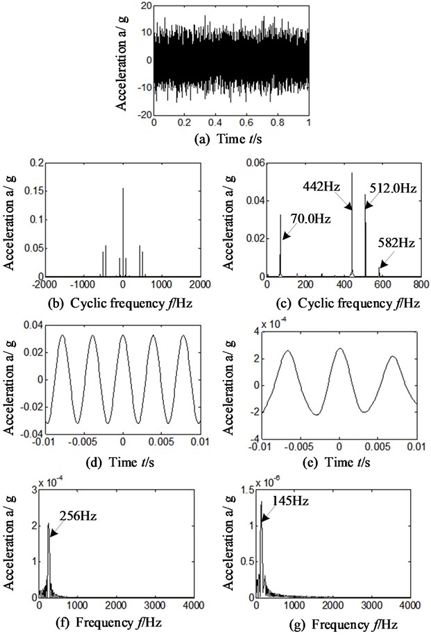
In order to verify the sensitivity of WT-AF-CY method to sensor installation direction when separating and extracting compound faults of inter-shaft bearing, the data selected was collected vertically at the same moment with section 3.1. The same wavelet function (sym6) and decomposition level (5 levels) is chosen, and the results are shown in Fig. 8. Fig. 8(a) is original time domain signal. Fig. 8(b)-(c) is the time-delay slice signal of cyclic autocorrelation function. Fig. 8(d)-(g) is the time-delay slice signal and frequency spectrum when cyclic frequency is equal to retainer rubbing outer ring and its double frequency (the result is similar in the case that the feature frequency of retainer and inner race or its double is selected)
Analyze Fig. 8 that is corresponding with sensor installed in vertical direction of rear casing of aero-engine and compare it with section 3.2 (sensor installed in horizontal direction). The following conclusions can be drawn:
(1) In Fig. 8 (b), (c), (e) and (g), when the data from the sensor in vertical direction is selected, there exists highlighted frequency components, 70 Hz and 145 Hz, in the slice signals of cyclic autocorrelation function. It is consistent with sensor installed in horizontal direction.
(2) In Fig. 8(b-d) and (f), there exists outstanding frequency components 256 Hz and 512 Hz. They correspond to the 3 time and 6-time of feature frequency (85.4 Hz) of retainer rubbing against inner race.
Namely, no matter with the signals collected by sensors in horizontal or vertical direction, the proposed WT-AF-CY method can equally identify the compound faults of intershaft bearing and the results of horizontal and vertical directions are similar (except the difference in amplitude).
4.4. MPR: a more visual way to identify
In order to identify fault types of bearings in simpler and more visual ways, the MPR is calculated by WT-AF-CY method according to Eqs. (15-16) and Fig. 6, Fig. 8. The results are exhibited on Fig. 9 and Table 3.
The Fig. 9 (a)-(b) respectively represents sensor installation in horizontal and vertical direction. The abscissa 1\2\3\4\5\6 respectively represents feature frequency band of rotational speed, retainer rubbing outer race, retainer rubbing inner race, outer race, inner race and rolling element. The feature frequencies bands are taken from subtract 5 Hz to add 5 Hz on the basis of calculated frequency according to Eqs. (10-16), in the consideration that there is a deviation between theoretical calculation and practice obtaining. For example, suppose that certain characteristic frequency is equal to MHz by calculation, and then the corresponding frequency band is selected from (-5) Hz to (+5) Hz, and double characteristic frequency band is selected from (2×-5) Hz to (2×+5) Hz and so on. The most representative characteristic frequency band of every feature frequency is selected in this paper. The ordinate represents calculated MPR between the selected characteristics frequency band and total frequency band (0 Hz-4000 Hz).
Fig. 8a) time domain, b)-c) slice signals, d)-g) time delay slice signals-approximate signal a5 for d), e) cyclic frequency equal to foc for e), g) cyclic frequency equal to 2foc – vertical direction
After analyzing Fig. 9 and Table 3, the following conclusions can be drawn:
It is observed from the Fig. 9(a)-(b) and Table 3, the calculated MPR is outstanding only in the positions where the feature frequency bands of retainer rubbing against outer and inner race are located, which is corresponding with 2 and 3 of -axis. The other MPRs obtained (the feature frequency bands of rotate frequency, inner race and rolling element) are not obvious.
Fig. 9MPR-proposed WT-AF-CY method
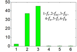
a) Different characteristic frequency band Sensor installation on horizontal direction
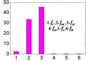
b) Different characteristic frequency band Sensor installation on vertical direction
Table 3Calculated MPR based on WT-AF-CY method
Direction | Feature frequency | |||||
Horizontal | 2.42 | 37.7 | 45.4 | 0.06 | 0.06 | 0.09 |
Vertical | 2.43 | 33.4 | 45.6 | 0.07 | 0.06 | 0.10 |
4.5. Common rolling bearing: proposed method
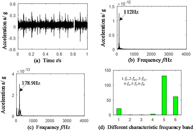
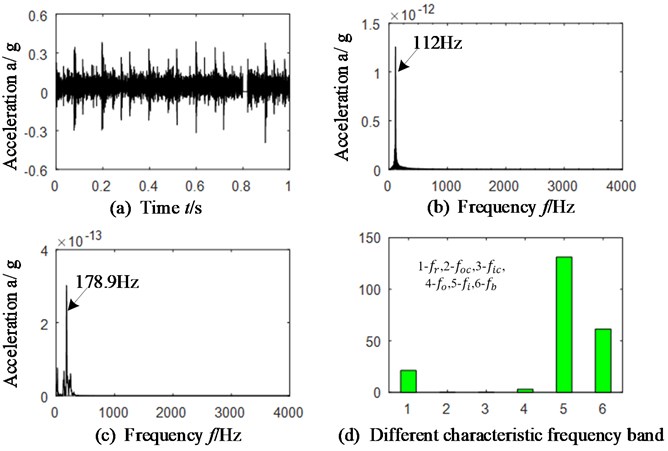
different compound faults (inner race and rolling elements) is selected for verifying the accuracy of WT-AF-CY method in common rolling bearings. The faulted rolling bearing is displayed on Fig. 10 and its geometric parameters are: the rolling elements diameter and numbers is respectively 9.6 mm and 7, and the pitch diameter is 36 mm. The rotational speed is 1492.5 r/min, and the rotational frequency is equal to 21.22 Hz. The feature frequency of retainer, rolling element, outer race and inner race of rolling bearing is respectively equal to 9.1 Hz, 43.3 Hz and 110.3 Hz by calculation according to Eqs. (10-12). The same wavelet function (sym6) and decomposition level (5 levels) is chosen, and the results are shown in Fig. 11 and Table 4. Fig. 11(a) is time domain signal. Fig. 11(b)-(c) is frequency spectrum of the time-delay slice signal when cyclic frequency is respectively equal to the feature characteristic of rolling elements and inner race. The Table 4 is the function value of calculated MPR by proposed method.
Fig. 10Faulted rolling bearing
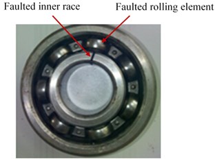
Table 4Calculated MPR based on WT-AF-CY method
Frequency horizontal | ||||||
Vertical | 21.2 | – | – | 3.03 | 131.2 | 61.44 |
After analyzing Fig. 11(b)-(c), it can be found that the outstanding fault feature frequency is 112 Hz which is corresponding with feature frequency (110.3) of inner race and 178.9 Hz which matches 4-times of rolling elements feature frequency (43.3 Hz). Therefore, compound faults of rolling bearing can be identified.
The results are similar in Fig. 11(d) and Fig. 5-9, the calculated MPR is outstanding only in those positions of the rotational speed, inner race and rolling element characteristic frequency bands, which is corresponding with 1, 5 and 6 of -axis.
That is to say, no matter for common rolling bearings or intershaft bearings of aero-engine, the results of characteristic extraction of compound faults remains the same based on proposed method.
Fig. 11a) Time domain of common bearing, b)-c) slice signals, cyclic frequency equal to fi and fb, d) MPR – vertical direction
5. Conclusions
The autocorrelation function is combined with wavelet transform and cyclostationary theory to identify the compound faults including the ones of intershaft bearings and common rolling bearings. Meanwhile, the MPR is calculated in order to identify the fault type of bearings in simpler and more visual ways. The following conclusions can be drawn:
1) The cyclic autocorrelation alone and wavelet transform combined with threshold value denoising cannot extract the fault characteristic frequency of intershaft bearings or common rollings.
2) The proposed method can not only extract and separate the compound faults feature precisely, but also can identify the compound fault type of intershaft bearing as well as common rolling bearings correctly and effectively.
3) The proposed method is insensitivity to installation direction of sensors. No matter acceleration sensors are installed vertically or horizontally, the proposed method can extract the characteristic frequency of bearing correctly.
4) The calculated MPR can also identify the compound faults type of intershaft bearings and common rolling bearings in more visual and simpler way no matter acceleration sensors are installed vertically or horizontally.
References
-
I. El-Thalji and E. Jantunen, “A summary of fault modelling and predictive health monitoring of rolling element bearings,” Mechanical Systems and Signal Processing, Vol. 60-61, pp. 252–272, Aug. 2015, https://doi.org/10.1016/j.ymssp.2015.02.008
-
D. Zhang and D. Yu, “Multi-fault diagnosis of gearbox based on resonance-based signal sparse decomposition and comb filter,” Measurement, Vol. 103, pp. 361–369, Jun. 2017, https://doi.org/10.1016/j.measurement.2017.03.006
-
Wang Guobiao et al., “Basic research on machinery fault diagnosis-what is the prescription,” (in Chinese), Journal of Mechanical Engineering, Vol. 49, No. 1, p. 63, 2013.
-
Zhang Ke, Zhou Donghua, and Chai Yi, “Review of multiple fault diagnosis method,” (in Chinese), Control Theory and Applications, Vol. 32, No. 9, pp. 1143–1157, 2015.
-
Liao Mingfu et al., “Fault characteristics and diagnosis method of intershaft bearing in aero-engine,” (in Chinese), Journal of Aerospace Power, Vol. 28, No. 12, pp. 2752–2758, 2013.
-
Qiao Baodong, Ge Xiangdong, and Zhang Dongming, “An analysis method for vibration fault of aero-engine intermediate bearing,” (in Chinese), Gas Turbine Experiment and Research, Vol. 28, No. 2, pp. 37–40, 2015.
-
Hu Xuan, Luo Guihuo, and Gao Deping, “Performance analysis of aero-engine intershaft bearing,” (in Chinese), Journal of Aerospace Power, Vol. 22, No. 3, pp. 439–443, 2007.
-
Liao Mingfu, Ma Zhenguo, and Deng Wei, “Vibration analysis on turbofan engine intershaft bearing with outer race defect,” Journal of Aerospace Power, Vol. 26, No. 11, pp. 2422–2426, 2011.
-
J. Antoni, F. Bonnardot, A. Raad, and M. El Badaoui, “Cyclostationary modelling of rotating machine vibration signals,” Mechanical Systems and Signal Processing, Vol. 18, No. 6, pp. 1285–1314, Nov. 2004, https://doi.org/10.1016/s0888-3270(03)00088-8
-
Chen Jin and Guangming Dong, Cyclostationary theory and method of machine fault characteristic extraction. (in Chinese), Shanghai: Shanghai Jiaotong University Press, 2013, pp. 97–101.
-
L. Li and L. Qu, “Cyclic statistics in rolling bearing diagnosis,” (in Chinese), Journal of Sound and Vibration, Vol. 267, No. 2, pp. 253–265, Oct. 2003, https://doi.org/10.1016/s0022-460x(02)01412-8
-
R. B. Randall, J. Antoni, and S. Chobsaard, “The relationship between spectral correlation and envelope analysis in the diagnostics of bearing faults and other cyclostationary machine signals,” Mechanical Systems and Signal Processing, Vol. 15, No. 5, pp. 945–962, Sep. 2001, https://doi.org/10.1006/mssp.2001.1415
-
J. Antoni, F. Guillet, M. El Badaoui, and F. Bonnardot, “Blind separation of convolved cyclostationary processes,” Signal Processing, Vol. 85, No. 1, pp. 51–66, Jan. 2005, https://doi.org/10.1016/j.sigpro.2004.08.014
-
Luo Honglin, Liu Xiaofeng, and Bo Lin, “Second-order directional cyclostationarity for oil-whip in journal bearing,” Journal of Vibration and Shock, Vol. 35, No. 4, pp. 49–55, 2016.
-
Lu Na, Xiao Zhihua, and O. P. Malik, “Feature extraction using adaptive multwavelets and synthetic detection index for rotor fault diagnosis of rotating machinery,” Mechanical Systems and Signal Processing, Vol. 52-53, No. 2, pp. 393–415, 2015.
-
Huang Baoyu, Zhang Yongxiang, and Zhao Lei, “Research on fault diagnosis method of rolling bearings based on cuckoo search algorithm and maximum second order cyclostationary blind deconvolution,” (in Chinese), Journal of Mechanical Engineering, Vol. 57, No. 9, pp. 99–107, 2021.
-
Wu Bin, Wang Min, Kang Jing, and Luo Yuegang, “Fault vibration signal feature of rolling bearing and its diagnosis method,” (in Chinese), Journal of Dalian University of Technology, Vol. 53, No. 1, pp. 76–81, 2013.
-
S. Abbasion, A. Rafsanjani, A. Farshidianfar, and N. Irani, “Rolling element bearings multi-fault classification based on the wavelet denoising and support vector machine,” Mechanical Systems and Signal Processing, Vol. 21, No. 7, pp. 2933–2945, Oct. 2007, https://doi.org/10.1016/j.ymssp.2007.02.003
-
C. Shen, D. Wang, F. Kong, and P. W. Tse, “Fault diagnosis of rotating machinery based on the statistical parameters of wavelet packet paving and a generic support vector regressive classifier,” Measurement, Vol. 46, No. 4, pp. 1551–1564, May 2013, https://doi.org/10.1016/j.measurement.2012.12.011
-
Xu Yajun, Yu Dejie, and Liu Jian, “Fault diagnosis of roller bearings based on chirplet path pursuit and order cyclostationary demodulation,” Journal of Aerospace Power, Vol. 28, No. 11, pp. 2600–2608, 2013.
-
Shen Zhengwei, Shi Tian, and Shen Yanan, “Construction of a symmetrical shift-invariant fractional overcomplete wavelet and its application in bearing fault diagnosis,” (in Chinese), Chinese Journal of Engineering, Vol. 37, No. 3, pp. 378–384, 2015.
-
Liao Chuanjun, Li Xuejun, and Liu Deshun, “Application of reassigned wavelet scalogram in feature extraction based on acoustic emission signa,” (in Chinese), Journal of Mechanical Engineering, Vol. 45, No. 2, pp. 273–279, 2009.
Cited by
About this article

This work was supported by National Natural Science Foundation of China (Grant No. 51605309), Natural Science Foundation of Liaoning Province (Grant No. 2019-ZD-0219), Aeronautical Science Foundation of China (Grant No. 201933054002) and Department of Education of Liaoning Province (Grant No. JYT19042).
