Abstract
The work is devoted to the problem of ensuring the near-resonance vibration modes stability of the technological vibromachines at fluctuating mass of processed material. Vibrations of the machine are excited by two self-synchronizing inertial vibroexciters driven by asynchronous electric motors rotating in opposite directions. A planar model of a vibromachine on a linear elastic suspension is considered. The interaction of the machine working element with the processed material is described using the added mass and viscous friction forces proportional to the material mass. To expand the frequency range of vibration exciter self-synchronization the possibility of using an additional elastic limiter is considered. The limiter is mounted between the working element and the machine foundation with a predetermined initial clearance. The modes of the working element vibrations and vibroexciter self-synchronization are analyzed depending on the change in the material mass and the initial clearance. It is found that the introduction of the elastic limiter allows to significantly reduce the sensitivity of the vibration amplitudes to material mass changes in the resonant frequency range, and also leads to stabilization of the mutual phase of vibration exciters rotation. A decrease in the initial clearance leads to an expansion of the stable operating modes frequency range, at the same time the vibration amplitudes decrease.
1. Introduction
There are many works devoted to the design and the dynamics analysis of resonant vibromachines, for example [1-7]. These machines, depending on the purpose and type of the technological process, differ in the schemes for the implementation of the technological process, the number of moving masses, the principles of excitation of the working element vibration, the laws of the vibrations realized, the types of vibration exciters used, etc. In a large number of cases vibrations of such vibromachines are excited by either single vibroexciter (electromagnetic, eccentric, inertial, etc.) or by several vibroexciters operating in a forced synchronization mode, for example, due to additional kinematic connections or additional vibroexciter drive control system, thereby achieving the desired configuration of the exciting force.
At the present time the vibromachine schemes with several self-synchronizing vibroexciters are widely used, which allows to significantly simplify the design of the vibromachine. General theory of vibroexciter self-synchronization in dynamic systems is considered in [8-10]. Applications of self-synchronizing vibroexciters to various types of vibromachines are considered, for example, in works [2, 9, 11, 12]. However, a certain adjustment of the system parameters and a choice of operating modes is required for vibroexciter self-synchronization with implementation of the necessary configuration of vibration excitation [2, 11, 13].
To ensure the vibromachine stability, regardless of the processed material mass, an above-resonant excitation mode is usually used. Recently, work on the use of the resonant excitation mode has been actively carried out. One of the problems of using vibromachines with self-synchronizing inertial vibroexciters in resonance modes is the high sensitivity of mutual phase of the vibroexciters rotation and vibration parameters of the working element to changes in the processed material characteristics [2, 13, 14].
In this work, to ensure the stability of vibration modes and vibroexciter self-synchronization in the resonant frequency range, the possibility of using an additional non-linear element - elastic limiter mounted with a certain initial clearance to the machine working element is considered. Note, that the issues of vibroexciter self-synchronization in the systems with nonlinear elastic elements are considered, for example, in [15-20]. However, in the majority of mentioned above works, these issues are considered when oscillations are excited far from resonances.
2. The vibromachine model
We will consider the dynamics of the vibromachine with self-synchronizing inertial vibroexciters in the resonance frequency range at changing mass of the processed material. It is assumed that the required technological process characteristics can be achieved with translational vibrations of the working element, which are realized in the case of excitation by a unidirectional force at synchronous-antiphase rotation of vibroexciters. This type of the working element vibrations is usually implemented for moving solid, liquid and multiphase media (vibratory conveyors), for separation, classification, screening (for example, vibrating screens), etc. A change in the material mass, which may arise due to unevenness (or difference) in the speeds of loading and unloading material from the working element, leads to a change in the dynamic properties of the system, the vibration mode (including the occurrence of undesirable swing motion of the working element), the mutual phase of vibroexciters rotation and a possible jump into above-resonant mode.
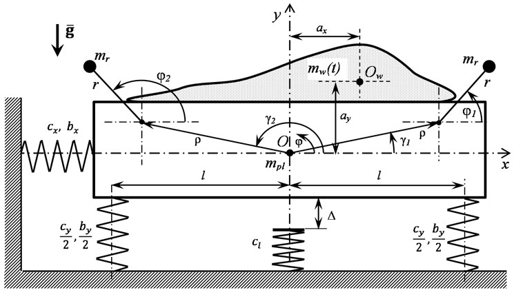
The vibromachine model (Fig. 1) consists of a working element – a platform modeled by a rigid body of mass and moment of inertia relative to its center of mass at point . The platform is suspended on a fixed base using linear elastic elements with coefficients of stiffness , /2 and damping , /2. The platform is able to vibrate in the plane, described by the and displacements of its center of mass along the corresponding coordinate axes and the rotation angle relative to its position at undeformed elastic elements. A linear elastic limiter with a stiffness coefficient is mounted under the platform at a distance . The platform vibrations are excited by two self-synchronizing inertial vibroexciters rotating in opposite directions. The exciters have identical imbalances and are driven by the same asynchronous type electric motors. The torque characteristics of the electric motors have a pronounced nonlinear dependence on the rotor speed associated with the rotor slip and are described by the Kloss’s formula [10]:
where 1, 2 is the number of the vibroexciter, and are, respectively, the critical torque and slip of the motor, , is the synchronous rotational speed of the motor, is the number of the motor poles pairs, is the frequency of the supply voltage, is the coefficient taking into account the direction of the torque action ( corresponds to the counterclockwise action of the motor torque).
The interaction of the platform with the processed material is described by the added mass and the moment of inertia relative to its own center of mass at point , as well as by the forces , and the moment of equivalent viscous friction, proportional to the material mass and platform velocities , , [11, 13]:
where is the mass of the platform with the material, is the moment of inertia of the platform with the material relative to point , , are the distances between the mass centers of the material and the platform in the directions and , , is the specific (per unit volume) coefficient of viscous friction, is the material bulk density.
Note that, in reality, the forces of interaction between the platform and the material are of a more complex character, depending significantly on the modes of the material motion relative to the platform, however the adopted approximation, according to [11, 13], sufficiently describes the effect of the material on the working element vibrations. The corresponding coefficients in Eq. (1) can be obtained experimentally or by calculation taking into account the physical and mechanical properties of the material and the laws of its motion along the working element.
The equations of the system motion, taking into account the time variable mass of the material, have the form:
where:
dotes denote differentiation with respect to dimensionless time , – time scale, tilde sign denotes the dimensionless values of displacements and dimensions, taking into account the selected scale :
Fig. 1The vibromachine model
3. Influence of the limiter parameters on the model dynamic characteristics
To analyze the influence of the limiter parameters on the model dynamics, its frequency characteristics were obtained by numerical simulation. The calculations were carried out for different values of the material mass = [0, 0.4] and different values of the initial clearance at different frequency of the electric motors power supply = [0.9, 2.6]. The selected range of the material mass change is determined by the usually recommended values of the payload on the vibromachine working element and the frequency change range covers the range of all resonant frequencies for the selected machine parameters: , , , , , , , , 4.4×10⁻⁶, 2.717×10⁻³, 7.143×10⁻³, 153.7, –1, 1, 0.177. 0.46, 2, = 120.7, , = 4.414.
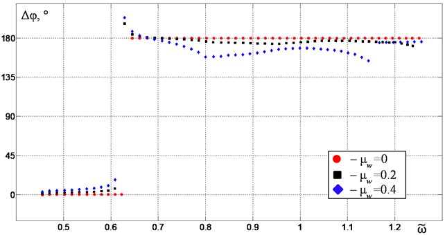
The extrema of the platform vertical vibrations {} and the phase shift of the vibroexciters rotation Δφ depending on their synchronous rotation frequency for different values of in the case of vibrations without contact with the limiter are shown in Fig. 2 and Fig. 3. Intensive vertical vibrations are excited near the second resonant frequency. In this case, in the absence of material on the platform in the frequency range between the first and second resonances, stable synchronous-antiphase rotation of vibroexciters with a phase shift 180° is realized, at which only the required vertical oscillations of the platform are excited. Near the second resonance an increase in the material mass leads to a deviation of the phase shift from 180°, which causes the excitation of unwanted horizontal and angular vibrations of the platform. Moreover, as one approaches the resonant frequency, this deviation increases, which is due to a resistance forces increase because of an increase in vibration amplitudes. Thus, the dynamic characteristics of the system near the second resonant frequency are highly sensitive to the changes in the material mass, which makes it difficult to use resonance modes as operating one.
Fig. 2The extrema of the platform vertical vibrations {y~max, y~min} depending on the excitation frequency ω~ in the case of no contact with the limiter: red circular points – at μw= 0, black square points – at μw= 0.2, blue diamond points – at μw= 0.4
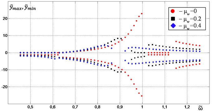
Fig. 4 and Fig. 5 show the characteristics similar to those indicated above in the case of the limiter mounted with an initial clearance of = 7.24. The clearance value is chosen so that contact with the limiter is guaranteed at the maximum permissible mass of the material, as one can see it in Fig. 2. The introduction of the limiter leads to a significant decrease in the sensitivity of the vertical vibration peak-to-peak amplitudes to changes in the material mass in the resonant frequency range (Fig. 4). In this case, the frequency range of possible modes of vertical vibrations excitation significantly expands due to the stabilization of the phase shift of vibration exciters rotation near 180° (Fig. 5).
Fig. 3Phase shift Δφ depending on the excitation frequency ω~ in the case of no contact with the limiter: red circular points – at μw= 0, black square points – at μw= 0.2, blue diamond points – at μw= 0.4
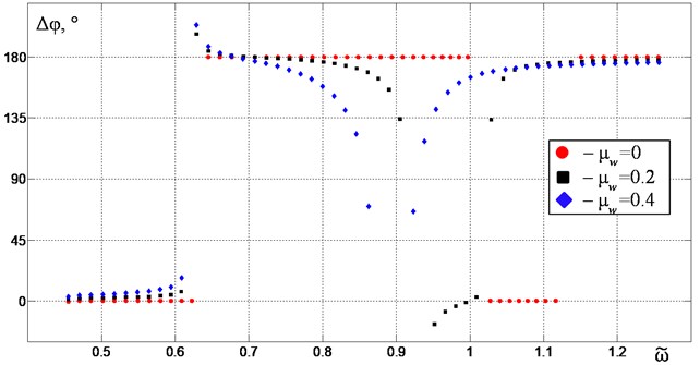
Fig. 4The extrema of the platform vertical vibrations {y~max, y~min} depending on the excitation frequency ω~ for Δ~ = 7.24: red circular points – at μw= 0, black square points – at μw= 0.2, blue diamond points – at μw= 0.4
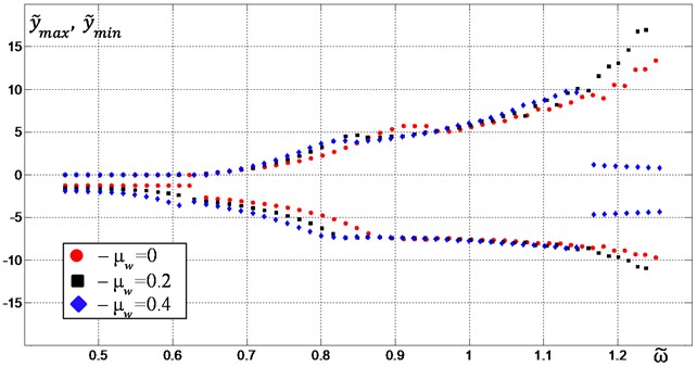
Fig. 5Phase shift Δφ depending on the excitation frequency ω~ for Δ~ = 7.2: red circular points – at μw= 0, black square points – at μw= 0.2, blue diamond points – at μw= 0.4
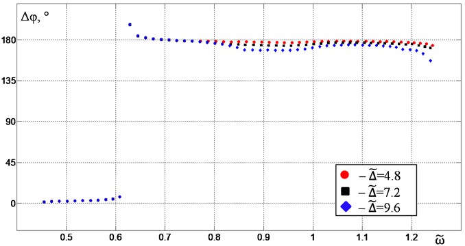
For a constant mass of the material, an increase in the initial clearance leads to an increase in the vibration amplitudes (Fig. 6) and a slight increase in the deviation of the phase shift of the vibroexciters rotation from the required value 180° (Fig. 7).
Fig. 6The extrema of the platform vertical vibrations {y~max, y~min} depending on the excitation frequency ω~ for μw= 0.2: red circular points – at Δ~ = 4.8, black square points – at Δ~ = 7.2, blue diamond points – at Δ~ = 9.6
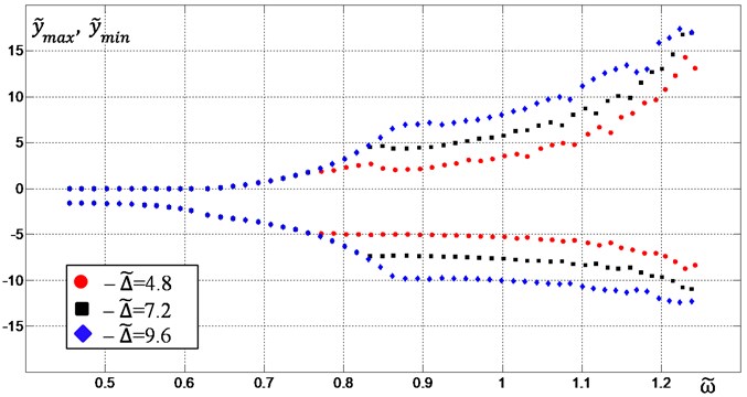
Fig. 7Phase shift Δφ depending on the excitation frequency ω~ for μw= 0.2: red circular points – at Δ~ = 4.8, black square points – at Δ~ = 7.2, blue diamond points – at Δ~ = 9.6
4. Dynamics of the model with a slowly varying mass of the processed material
The dynamic characteristics of the vibromachine model shown in the previous section represent its properties at different but constant in time parameter values. This section analyzes the dynamics of the model with the material mass slowly varying in time, associated with possible uneven material loading and unloading. The vibrations are excited with a constant frequency of the electric power supplied to the vibroexciter motors, which corresponds to the usual operating conditions of the machine without a control system. The simulation was carried out with a change in the material mass according to the harmonic law , where is the average value of the material mass usually allowed on the working element, and are the amplitude and the frequency of the law of mass change, and , is the average value of the synchronous rotational speed of the vibroexciters.
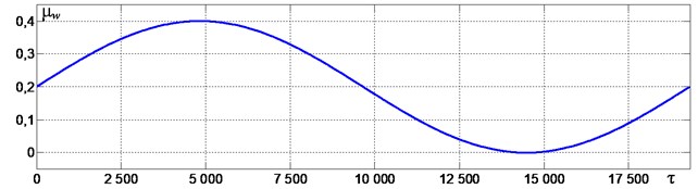
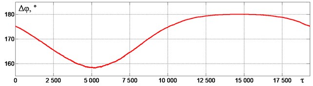
Fig. 8a) Change in the material mass in time, b) vibration oscillogram and phase trajectories and c) the phase shift of vibroexciters rotation Δφ at an excitation frequency of ω~ = 0.88
a)
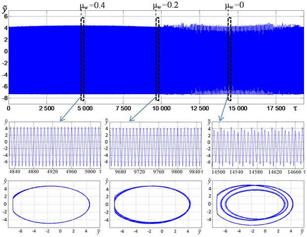
b)
c)
Fig. 8 shows the graphs characterizing the change in the material mass over time (Fig. 8(a)), vertical vibrations (Fig. 8(b)) and the phase shift of vibroexciters rotation (Fig. 8(c)) at , 1, 3.25×10⁻⁴, = 7.2 and an excitation frequency = 0.88. The selected value of the excitation frequency corresponds to the resonance tuning of the machine with a constant value of the material mass (see Fig. 2). Enlarged fragments of the oscillogram and the corresponding phase portraits of the vertical vibrations for the moments of time when the material mass reaches its maximum (at 4828), average (at 9656), and minimum (at 14484) values are shown in additional windows in Fig. 8(b). When the mass changes, the peak-to-peak amplitudes practically do not change. It can be seen in the corresponding phase portraits that with an increase in mass above the average value ( > 0.2) periodic oscillations are observed with one contact with the limiter per period, and with a decrease in mass below the average value ( < 0.2) – with one contact per three cycles of vibration. An increase in the material mass leads to a deviation of the phase shift of vibroexciters rotation from 180° by no more than 22° (Fig. 8(c)). Such a deviation can be considered quite satisfactory, since it does not lead to a noticeable decrease in the vibrations amplitude, but only slightly affects the working element trajectory.
5. Conclusions
The dynamics analysis of the vibromachine model shows that the introduction of an elastic limiter helps to stabilize the synchronous-antiphase mode of vibroexciters rotation in the frequency range near the second resonance, as well as leads to a significant decrease in the sensitivity of the vibration amplitudes to changes in the processed material mass. Thus, tuning to the resonant mode can be carried out only due to the rational choice of the elastic limiter parameters without the use of the excitation frequency control systems. The value of the clearance between the limiter and the platform significantly affects both the vibration amplitudes and the frequency range boundaries of the required vibrational modes, and can be used as one of the adjustable parameters in the development of controlled resonant vibromachines.
References
-
V. N. Poturaev, A. G. Chervonenko, and Yu. Ya. Obodan, Dynamics and strength of transport-technological vibration machines. (in Russian), Leningrad: Mashinostroenie, 1989.
-
E. E. Lavendelis, Vibration in the Technique, Handbook, Vol. 4, Vibration Processes and Machines. (in Russian), Moscow: Mashinostroenie, 1981.
-
S. L. Tsyfanskii, A. B. Oks, and V. I. Beresnevich, Nonlinear and parametric vibrations of technological vibration machines. (in Russian), Riga: Zinatne, 1991.
-
S. Abolfazl Zahedi and V. Babitsky, “Modeling of autoresonant control of a parametrically excited screen machine,” Journal of Sound and Vibration, Vol. 380, pp. 78–89, Oct. 2016, https://doi.org/10.1016/j.jsv.2016.06.011
-
Z. V. Despotovic, A. I. Ribic, and V. Sinik, “Power current control of a resonant vibratory conveyor having electromagnetic drive,” Journal of Power Electronics, Vol. 12, No. 4, pp. 678–689, 2012, https://doi.org/10.6113/jpe.2012.12.4.677
-
V. I. Antipov, “Dynamic of vibration machines with combinational parametric excitation,” (in Russian), Journal of Machinery Manufacture and Reliability, Vol. 2, pp. 13–17, 2001.
-
N. N. Dentsov and A. V. Koshelev, “Dynamics of a dual-mass resonant vibration screen in a first approximation,” VESTNIK of Samara University. Aerospace and Mechanical Engineering, Vol. 17, No. 3, p. 148–157, 2018, https://doi.org/10.18287/2541-7533-2018-17-3-148-157
-
I. I. Blekhman, Synchronization of Dynamical Systems. (in Russian), Moscow: Nauka, 1971.
-
H. Nijmeijer and A. Rodriguez-Angeles, Synchronization of mechanical systems. Singapore: World Scientific Publishing, 2003.
-
R. Nagaev, Dynamics of synchronizing systems. Berlin: Springer-Verlag, 2003.
-
L. A. Vaisberg, Design and Calculation of Vibrating Screens. (in Russian), Moscow: Nedra, 1986.
-
V. B. Vasilkov and Ye. V. Shishkin, “Dynamics of a vibrating device with torsionally suspended pendulums,” (in Russian), Obogashchenie Rud, Vol. 6, pp. 25–28, 2014.
-
I. I. Blekhman, Theory of Vibration Processes and Devices. Vibration Mechanics and Vibration Technology. (in Russian), St. Peterburg: ID Ruda I Metally, 2013.
-
Y.-Z. Jiang, K.-F. He, Y.-L. Dong, D.-L. Yang, and W. Sun, “Influence of Load Weight on Dynamic Response of Vibrating Screen,” Shock and Vibration, Vol. 2019, pp. 1–8, Apr. 2019, https://doi.org/10.1155/2019/4232730
-
I. I. Bikhovskiy, Fundamentals of the theory of vibration technology. (in Russian), Moscow: Mashinostroenie, 1968.
-
Z. Huang, G. Song, Z. Zhang, and X. Zhang, “Control Synchronization of Two Nonidentical Homodromy Exciters in Nonlinear Coupled Vibration System,” IEEE Access, Vol. 7, pp. 109934–109944, 2019, https://doi.org/10.1109/access.2019.2933033
-
L. Ye, L. He, W. Xiaopeng, and W. Bangchun, “Self-synchronization theory of a nonlinear vibration system driven by two exciters. Part 1: Theoretical analysis,” Journal of Vibroengineering, Vol. 16, No. 2, pp. 725–734, Mar. 2014.
-
X. Zhang, X. Kong, B. Wen, and C. Zhao, “Numerical and experimental study on synchronization of two exciters in a nonlinear vibrating system with multiple resonant types,” Nonlinear Dynamics, Vol. 82, No. 1-2, pp. 987–999, Oct. 2015, https://doi.org/10.1007/s11071-015-2212-0
-
X. Zhang, B. Wen, and C. Zhao, “Theoretical study on synchronization of two exciters in a nonlinear vibrating system with multiple resonant types,” Nonlinear Dynamics, Vol. 85, No. 1, pp. 141–154, Jul. 2016, https://doi.org/10.1007/s11071-016-2674-8
-
N. Zhang, “Self-synchronization characteristics of a class of nonlinear vibration system with asymmetrical hysteresis,” Journal of Low Frequency Noise, Vibration and Active Control, Vol. 39, No. 1, pp. 114–128, Mar. 2020, https://doi.org/10.1177/1461348419839512
Cited by
About this article

This research is funded by the Russian Science Foundation, Project No. 21-19-00183, https://rscf.ru/en/project/21-19-00183/.
