Abstract
In view of the cyclostationary characteristics of vibration signals from aero-engine, the combination of cyclic autocorrelation function and intrinsic timescale decomposition (ITD) has been proposed. According to the proposed method, vibration signals are decomposed by ITD algorithm to obtain the autocorrelation function of proper rotation components (PRC), based on which characteristic extraction and identification of compound faults of rolling bearings is made possible. To validate the effectiveness of method, an analysis has been given to the vibration signals of rolling bearings collected by sensors of different positions in different compound fault modes. As shown by results, the method combining ITD and cyclostationary theory can precisely and effectively extract the characteristic frequency relative to the type of faults and identify the compound faults.
1. Introduction
Rolling bearing is an important support part for rotation of aero-engine and extremely vulnerable working in high-speed and high-pressure environment. A bearing fault may have huge influence on performance of aero-engine and even weaken the safety of operation [1]. Therefore, state monitoring and fault diagnosis is of great significance. Vibration signal can fully reflect the dynamic properties of bearings. When one part of bearing is damaged, it will impact other components resulting in periodic impact force and vibration signal will create periodic peak pulse [2, 3]. As vibration signals of bearings are both non-linear and non-stationary, fault signals are often overwhelmed by noise signals adding to the difficulty of characteristic extraction [4, 5]. Besides, the faults of bearings often exist as being compound and characteristic extraction is far more difficult than single faults [6].
In recent years, multiple signal analysis methods have been introduced to bearing fault diagnosis to solve the difficulties in fault characteristics extraction, including empirical mode decomposition (EMD) [7], ensemble empirical mode decomposition (EEMD) [8, 9], variational mode decomposition (VMD) [10, 11], blind source separation [12] and so on. FREI brought forward ITD self-adaptive decomposition algorithm in 2007 [13], which was firstly applied to the field of electrical signal. Song, et al. pointed out the use of ITD algorithm to extract transient characteristics of radio station. By estimating the transient parameters of signal, they could detect signals and identify an individual station [14]. An, et al, proposed a quick algorithm based on intrinsic timescale decomposition [15] and the ITD algorithm was soon applied to the fault diagnosis of rotary machines, such as bearings and gears [16-18]. Due to the approximate symmetry and periodicity of operation state of rotary machine, its vibration signal has cyclostationary properties. For that, it will be more precise to extract the characteristics of faults with circular statistics. Wang, et al. proposed the method combing EMD and second order cyclostationary analysis [19]. Victor Girondin brought forward the fault detection method for bearings of helicopter based on frequency adjustment and cyclostationary analysis [20]. Literature [21] combined wavelet transforms and cyclic autocorrelation for the fault analysis of rolling bearings. Literature [22] proposed the application of cyclic autocorrelation function to test bed of wind power gear box. As correlation function can retain the properties of original signal while reducing the noise, autocorrelation function of signal can be analyzed based on cyclostationary theory.
For that, the paper proposes the combination of ITD algorithm, correlation analysis and cyclostationary theory to extract characteristics of compound faults of rolling bearings and identify the type of faults.
2. ITD-AF-CAF
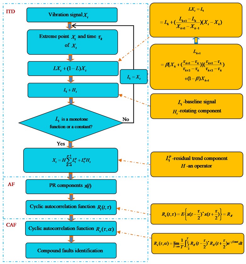
Given (0) is a real-value discrete signal to be resolved, baseline extractor ( is a variable varying with local extreme points of original signal during decomposition), baseline component, proper rotational component, residual trend component, , the extreme point and time of sequence (define ). is a linear zoom factor adjust the range of proper rotational component, , in which . The ITD decomposition process of signal is as shown in Eqs. (1)-(4) and Fig. 1:
Take as a new original signal and go on with Eqs. (1)-(2) until is smaller than the set threshold value or monotonic function. After ITD decomposition, can be expressed as:
where, , and * are respectively delay factor, statistical mean value and conjugate. has cyclostationary feature, if is a periodic function of time . In view of is a period function and can be acquired by means of Fourier series expansion:
, and respectively represent cycle frequency and autocorrelation function period, and then the Fourier transform coefficient can be shown:
where is cycle-autocorrelation function of as cycle frequency is equal to . The specific ITD-AF-CAF is as shown in Fig. 1.
Fig. 1Conceptual framework of ITD-AF-CAF Note: ITD, intrinsic timescale decomposition; AF, autocorrelation function; CAF, cyclic autocorrelation function
3. Rolling bearing compound faults experiment
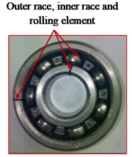
All data in this paper was collected from the test bed of rotor-rolling bearing designed by China Aero Engine Research Institute, which is as shown in Fig. 2. The test bed contains single-disk rotor with both ends supported by rolling bearings on bearing block. Working components include USB9234 data acquisition card provided by NI, B&K model 4508 acceleration sensors which collect acceleration signals and electrical vortex sensor which detects the rotation speed of rolling bearings. The compound faults of rolling bearings are as shown in Fig. 3, in which Fig. 3(a1)-(a3) corresponds to the compound faults of outer ring and a rolling element, inner ring and a rolling element, inner-outer ring and a rolling element, respectively. Geometrical parameters of bearings include: inner ring diameter 9.6 mm, pitch diameter 36 mm, number of rolling bodies, 7. The rotation speeds and characteristic frequencies of rolling bearings with compound faults are shown in Table 1.
Table 1Feature frequency of rolling bearing
Compound fault types | Rotation speed | Rotational frequency | Inner race feature frequency | outer race feature frequency | Rolling elements feature frequency |
Outer race and a rolling element | 182.7 r/min | 30.4 Hz | 134.8 Hz | 78.0 Hz | 52.9 Hz |
Inner race and a rolling element | 2013.4 r/min | 33.5 Hz | 148.8 Hz | 86.1 Hz | 58.4 Hz |
Inner, outer race and a rolling element | 1542.4 r/min | 25.7 Hz | 113.6 Hz | 66.0 Hz | 44.8 Hz |
Fig. 2Rotor-rolling bearing experiment rig
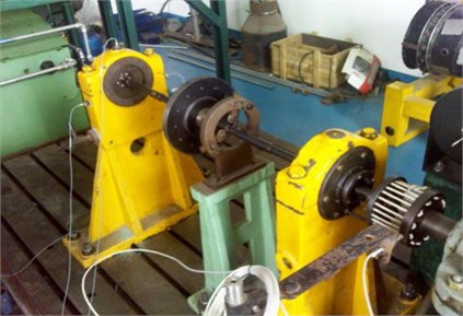
Fig. 3Rolling bearing compound faults for (a1)-(a3) compound faults of outer race and rolling element; inner race and rolling element; outer race, inner race and rolling element
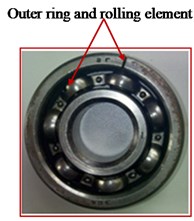
a1)
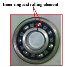
a2)
a3)
4. Characteristic extraction of compound faults of rolling bearings
4.1. ITD-AF: common method
For a comparative analysis to validate the effectiveness of method, vibration signals are decomposed based on ITD algorithm and characteristics of compound faults are extracted according to the frequency spectrum of autocorrelation function of rotation components (ITD-AF).
Limited by the length of paper, we took the vibration acceleration signal (faults 1 in Table 1) collected by the sensor in vertical direction as an example when compound faults of inner ring and a rolling element occurred, and extracted the characteristics of compound faults based on ITD-AF algorithm. The result is shown in Fig. 4, in which rotation speed of tester is 2013.4 r/min, rotation frequency 33.5 Hz (2013.4/60 = 33.5) obtained by calculation. According to formula 1-4 and geometrical parameters, we can have the characteristic frequency of inner ring, outer ring and rolling elements is 148.8 Hz, 86.1.0 Hz and 58.4 Hz, respectively. Fig. 4(a), (b) and (c) is the time domain, frequency spectrum and its partial zoom of vibration acceleration signal. Fig. 4(a1)-(a4) corresponds to the time domain of PRC1, PRC2, PRC3 and PRC4 after ITD decomposition. Fig. 4(b1)-(b4) is the autocorrelation function of Fig. 4(a1)-(a4). Fig. 4(c1)-(c4) is the frequency spectrum of Fig. 4(b1)-(b4). Relation of frequency components and characteristic frequency of bearing in Fig. 4(c1)-(c4) is as shown in Table 2.
Fig. 4Rolling bearing compound faults feature extraction-ITD-AF
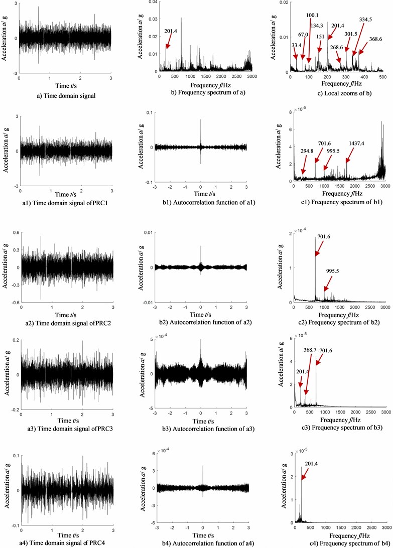
Table 2Relation between frequency components and fault types of rolling bearing-ITD-AF-vertical (Hz)
PRC | Frequency | Feature frequency | Frequency | Feature frequency |
PR1 | (1) 294.8 | 294.8/5 = 58.9 ≈ 58.4 | (3) 995.5 | 995.5/17 = 58.5 ≈ 58.4 |
(2) 701.6 | 701.6/12 = 58.5 ≈ 58.4 | (4) 1437 | (1437-33.5)/24 = 58.5 | |
PR2 | (1) 701.6 | 701.6/12 = 58.5 ≈ 58.4 | (2) 995.5 | 995.5/17 = 58.5 ≈ 58.4 |
PR3 | (1) 201.4 | 201.4/6 = 33.5 | (2) 368.7 | 368.7/11 = 33.5 |
(3) 701.6 | 701.6/12 = 58.5 ≈ 58.4 | |||
PR4 | (1) 201.4 | 201.4/6 = 33.5 |
With the analysis of Fig. 4 and Table 2, the following conclusions can be drawn:
In the frequency spectrum of original signal in Fig. 4(b) and (c), the frequency components are very complicated in that most of them are rotation frequency (33.5 Hz) and the components of frequency multiplication. There is no characteristic frequency of rolling elements (58.4 Hz), inner ring (148.8 Hz) and their frequency multiplication observed. That means frequency spectrum alone cannot identify a fault of bearings, not to mention the identification of compound faults types.
As found from the analysis of Fig. 4(c1), (c2), (c3), (c4) and Table 2, there is obvious characteristic frequency (58.4 Hz) of rolling elements and its frequency multiplication (701.6 Hz, 995.5 Hz, 1437 Hz) which can be found from the frequency spectrum of autocorrelation function of each rotation component after ITD decomposition, but without obvious characteristic frequency (148.8 Hz) of inner ring and its frequency multiplication component, which means that the method based on ITD-AF can partly extract the characteristic frequency of compound faults, but not comprehensively. For that, this method is incapable to make precise judgment upon the type of compound faults of bearings.
4.2. ITD-AF-CAF: a new method
To be more precise and effective in identifying the compound faults of rolling bearings, ITD algorithm is introduced into the framework of cyclostationary theory. Cyclic autocorrelation function is combined with the autocorrelation function of each PR component after ITD decomposition to extract the characteristics of compound faults of rolling bearings. For a comparison validation, the data for ITD-AF-CAF analysis is completely the same with Section 4.1 and the result is shown in Fig. 5. Limited by the length of paper, Fig. 5 only shows the cyclic autocorrelation function of autocorrelation function of PRC2 and PRC4 (pick up the PR components of ideal effect). Fig. 5(a1) is autocorrelation function of PRC2 (completely the same with Fig. 4(b2); the time domain signal of PRC2 is shown in Fig. 4(a2)); Fig. 5(a2)-(a3) is the cyclic autocorrelation function of Fig. 5(a1) and its partial zoom; Fig. 5(a4)-(a5) is the sliced signal of cyclic autocorrelation function of autocorrelation function of PRC2; Fig. 5(b1) is the autocorrelation function of PRC4 (completely the same with Fig. 4(b4) and the time domain signal of PRC4 is shown in Fig. 4(a4)); Fig. 5(b2)-(b3) is the cyclic autocorrelation function of Fig. 5(b1) and its partial zoom; Fig. 5(b4)-(b5) is the sliced signal of cyclic autocorrelation function of autocorrelation function of PRC4.
Corresponding relation between each frequency component and characteristic frequency of bearing in Fig. 5 is shown in Fig. 3.
Table 3Relation between frequency component and fault types of rolling bearing-vertical (Hz)
PRC | Frequency | Feature frequency | Frequency | Feature frequency |
PRC2 | (1) 33.1 | 33.1 ≈ 33.5 | (3) 147 | 147 ≈ 148.8 |
(2) 67.0 | 67.0/2 = 33.5 | (4) 295 | 295/2 = 147.5 ≈ 148.8 | |
(5) 404 | 404/7 = 57.7 ≈ 58.4 | |||
PRC4 | (1) 67.0 | 67.0/2 = 33.5 | (2) 101 | 101/3 = 33.6 ≈ 33.5 |
(3) 352 | 352/6 = 58.6 ≈ 58.4 | (4) 404 | 404/7 = 57.7 ≈ 58.4 |
Fig. 5rolling bearing compound faults feature extraction-ITD-AF-CAF
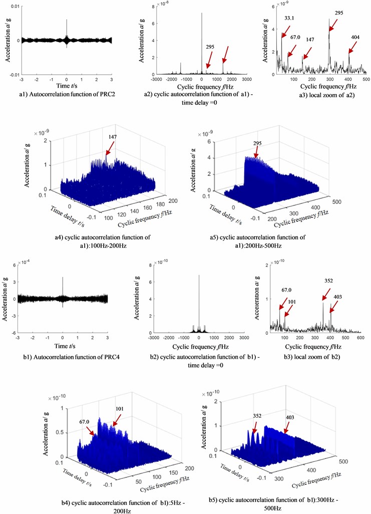
With the analysis of Fig. 5 and Table 3, the following conclusions can be drawn:
Outstanding frequency components in PR2 component are as follow:
(1) 147 Hz, corresponding to characteristic frequency of inner ring (148.8 Hz);
(2) 295 Hz, corresponding to the double characteristic frequency of inner ring;
(3) 404 Hz, corresponding to the 7-time (404/7 = 57.7) characteristic frequency of rolling elements (58.4 Hz);
In PR4 component:
(1) 352 Hz, corresponding to the 6-time characteristic frequency of rolling elements (58.4 Hz);
(2) 404 Hz, corresponding to the 7-time characteristic frequency of rolling elements (58.4 Hz);
Namely, when a compound faults of inner ring and a rolling element occurs, the proposed ITD-AF-CAF can provide the characteristic frequency consistent with the type of compound faults of bearing. That means the proposed ITD-AF-CAF can make precise judgment on the type of compound faults of bearings.
5. Influencing factors
To validate the effectiveness of ITD-AF-CAF in characteristic extraction of compound faults of rolling bearing, an analysis is given to the vibration signals collected by sensors from different directions and in different compound faults based on ITD-AF-CAF method.
To analyze the sensibility of analysis method to installation direction of sensors, signals collected from horizontal direction are compared with the ones from vertical direction. Due to the limited length of paper, we took the compound faults of outer ring and a rolling element as an example and the result is shown in Fig. 6(a1)-(b7). To analyze the sensibility of analysis method to the type of compound faults, an analysis was given to the vibration acceleration signals collected from compound faults of outer ring and a rolling element, and results are shown in Fig. 6(c1)-(c7).
When the rotation speed is 1823.7 r/min in compound faults of outer ring and rolling body, we can have the characteristic frequency of inner ring, outer ring and a rolling element, as follow: 134.8 Hz, 78.0 Hz and 52.9 Hz (corresponding to the second type of fault in Table 2). When the rotation speed is 1542.4 r/min in compound faults of inner ring, outer ring and a rolling element, we can have the characteristic frequency of inner ring, outer ring and rolling elements as follow: 113.6 Hz, 66.0 Hz and 44.8 Hz (corresponding to the third type of faults in Table 2).
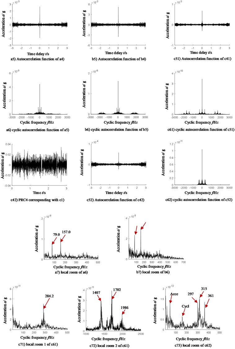
Fig. 6(a1)-(a7) and 6(b1)-(b7) corresponds to the acceleration signals collected by sensors from horizontal and vertical directions when compound faults of outer ring and a rolling element occur. Fig. 6(c1)-(c73) corresponds to the acceleration signals collected by sensors from vertical directions when compound faults of outer ring, inner ring and a rolling element occur.
Fig. 6(a1), (b1) and (c1) corresponds to the time domain of acceleration signal; Fig. 6(a2), (b2) and (c2) to the frequency spectrum of Fig. 6(a1), (b1) and (c1); Fig. 6(a3), (b3) and (c3) to the partial zoom of frequency spectrum of Fig. 6(a2), (b2) and (c2); Fig. 6(a4), (b4) and (c4) to the time domain of PRC1 (an ideal one) obtained by ITD decomposition of Fig. 6(a3) and (b3); Fig. 6(c41) and (c42) to the time domain of PRC1 and PRC4 (an ideal one) obtained by ITD decomposition of fig. 6(c3); Fig. 6(a5), (b5), (c51) and (c52) to the autocorrelation function of Fig. 6(a4), (b4), (c41) and (c42); Fig. 6(a6), (b6), (c61) and (c62) to the cyclic autocorrelation function of Fig. 6(a5), (b5), (c51) and (c52); Fig. 6(a7) and (b7) to the partial zoom of Fig. (a6) and (b6). Fig. 6(c71) and (c72) to the partial zoom of Fig. 6(c61); Fig. (c73) to the partial zoom of Fig. 6(c62). The corresponding relation between frequency components and characteristic frequency of bearings in Fig. 7 is shown in Table 4.
Analyzing Fig. 6(a7), (b7) and Table 4, in case of compound faults of outer ring and a rolling element, the following conclusions can be drawn:
No matter sensors are installed in horizontal direction or vertical, the proposed method can effectively extract the characteristic frequency 79 Hz of outer ring fault and triple characteristic frequency of rolling elements (157/3 = 52.3Hz) which matches with the type of faults. Therefore, the proposed method can judge the type of compound faults of bearings, namely insensitivity to installation direction of sensors.
After analyzing Fig. 6(c71), (c72), (c73) and table 4, in case of compound faults of outer ring, inner ring and a rolling element, the relation of frequency component and characteristic frequency of bearings is shown as follows:
Outstanding frequency components in PRC2 are as follow:
(1) 284.2 Hz, corresponding to the sum of characteristic frequency of inner ring (113.6 Hz) and rolling elements (44.8 Hz), and 5-time rotation frequency ((284.2 – 113.6-44.8)/5 = 25.1);
(2) 1407 Hz, corresponding to the 21-time characteristic frequency (1407/21 = 67 Hz) of outer ring (66.0 Hz);
(3) 1702 Hz, corresponding to the 26-time characteristic frequency (1702/26 = 65.5 Hz) of outer ring (66.0 Hz);
(4) 1986 Hz, corresponding to the 30-time characteristic frequency (1986/30 = 66.2 Hz) of outer ring (66.0 Hz);
Outstanding frequency components in PRC4 are as follow:
(1) 46 Hz, corresponding to the characteristic frequency of rolling elements;
(2) 157 Hz, corresponding to the sum of characteristic frequency of rolling elements and inner ring, (113.6 + 44.8 = 158.4 Hz);
(3) 297 Hz, corresponding to the sum of 4-time characteristic frequency of inner ring and rolling elements, (297 – 113.6)/4 = 45.8);
(4) 315 Hz, corresponding to the 7-time characteristic frequency of rolling elements (315/7 = 45);
(5) 361 Hz, corresponding to the 8-time characteristic frequency of rolling elements (361/8 = 45.1).
Fig. 6Rolling bearing compound faults feature extraction-ITD-AF-CAF
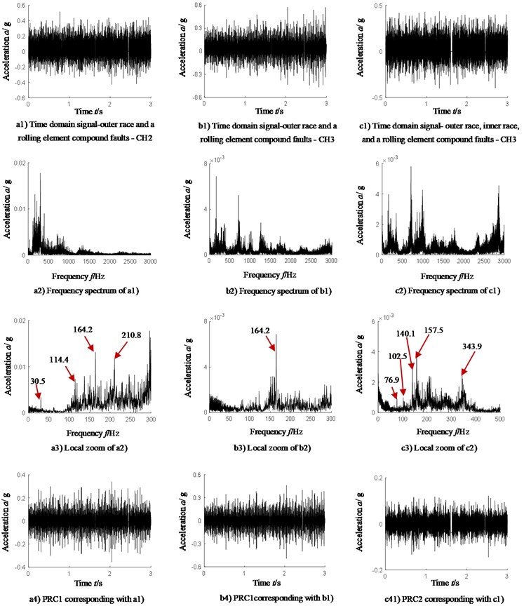
It can be found that:
(1) The proposed ITD-AF-CAF method can effectively extract the characteristic frequency matched with the type of faults no matter sensors are installed horizontally or vertically, and thereby make effective judgment on the type of compound faults. That means the proposed method is insensitive to installation direction of sensors;
(2) No matter for compound faults of inner ring and a rolling element, outer ring and a rolling element, or inner ring, outer ring and a rolling element, the proposed ITD-AF-CAF method can effectively extract the matching characteristic frequency of fault types, and thereby make effective judgment on the types of compound faults of bearings.
Table 4Relation between frequency component and fault types of rolling bearing-vertical (Hz)
Compound fault types | Sensors installed direction | PRC | Frequency | Feature frequency | Frequency | Feature frequency |
Outer race and rolling element | Horizontal | PRC1 | (1) 79 | 79 ≈ 78 | (2) 157 | 157/3 = 52.3 ≈ 52.9 |
Outer race and rolling element | Vertical | PRC1 | (1) 79 | 79 ≈ 78 | (2) 157 | 157/3 = 52.3 ≈ 52.9 |
Outer race, inner race and rolling element | Vertical | PRC2 | (1) 284.2 | (284.2-113.6-44.8)/5 = 25 | (2) 1407 | 1407/21 = 67 ≈ 66 |
(3) 1702 | 1702/26 = 65.5 ≈ 66 | (4) 1986 | 1986/30 = 66.2 ≈ 66 | |||
PRC4 | (1) 46 | 46 ≈ 44.8 | (2) 157 | 44.8+113.6 = 158.4 ≈ 157 | ||
(3) 297 | (297-113.6)/4 = 45.8 ≈ 44.8 | (4) 315 | 315/7 = 45 ≈ 44.8 | |||
(5) 361 | 361/8 = 45.1 |
6. Conclusions
Due to the approximate symmetry and periodicity of operation state of rotation machine, its vibration signal has cyclostationary properties. Therefore, cyclostationary theory and ITD algorithm is combined to make correct and effective identification of compound faults in bearings.
To prove the superiority of the proposed method, a comparative analysis has been given to the proposed method and common algorithm (combined ITD and autocorrelation analysis) and the following conclusions can be drawn:
1) The common algorithm (combined ITD and autocorrelation analysis) can partly extract the characteristic frequency of bearings, but not comprehensively, so that it cannot extract the characteristic frequencies matched with the type of compound faults, and fails to make precise judgment on the type of compound faults.
2) The combination of ITD, autocorrelation analysis and cyclostationary theory can precisely extract the characteristic frequencies matched with the type of faults, and thereby judge the type of compound faults of rolling element.
3) An analysis has been given to signals collected by sensors from different directions (horizontal or vertical). The conclusion indicates that the proposed ITD-AF-CAF method shows insensitivity to installation direction of sensors. No matter where sensors are installed in horizontal or vertical, the proposed method can effectively extract the characteristic frequency of rolling elements which matches with the type of faults.
4) Another analysis has been given to vibration signals of different types of compound faults (inner ring and a rolling element, outer ring and a rolling element, inner ring, outer ring and a rolling element). The conclusion indicates that the proposed ITD-AF-CAF method shows insensitivity to the type of compound faults.
References
-
Li Xianze et al., “Fault diagnosis method of rolling bearings based on SGMD, L-kurtosis and log-SAM,” (in Chinese), Noise and Vibration Control, Vol. 40, No. 6, pp. 121–127, 2020, https://doi.org/10.3969/j.issn.1006-1355.2020.06.020
-
Z. J. Huang Zhichu, “Faulty impulse signals extraction and diagnosis of rolling element bearing: A blind deconvolution method,” (in Chinese), Journal of Vibration and Shock, Vol. 25, No. 3, pp. 150–154, 2006, https://doi.org/ 10.13465/j.cnki.jvs.2006.03.034
-
A. Kumar, C. P. Gandhi, Y. Zhou, H. Tang, and J. Xiang, “Fault diagnosis of rolling element bearing based on symmetric cross entropy of neutrosophic sets,” Measurement, Vol. 152, p. 107318, Feb. 2020, https://doi.org/10.1016/j.measurement.2019.107318
-
Dong Zhilin et al., “A rolling bearing fault diagnosis method of time-shifted multi-scale permutation entropy combining with ELM,” (in Chinese), Mechanical Science and Technology for Aerospace Engineering, pp. 1–7, 2020, https://doi.org/10.13433/j.cnki.1003-8728.20200252
-
C. He, T. Wu, R. Gu, Z. Jin, R. Ma, and H. Qu, “Rolling bearing fault diagnosis based on composite multiscale permutation entropy and reverse cognitive fruit fly optimization algorithm – Extreme learning machine,” Measurement, Vol. 173, p. 108636, Mar. 2021, https://doi.org/10.1016/j.measurement.2020.108636
-
G. Wang, “Basic research on machinery fault diagnosis-what is the prescription,” Journal of Mechanical Engineering, Vol. 49, No. 1, p. 63, 2013, https://doi.org/10.3901/jme.2013.01.063
-
N. E. Huang et al., “The empirical mode decomposition and the Hilbert spectrum for nonlinear and non-stationary time series analysis,” Proceedings of the Royal Society of London. Series A: Mathematical, Physical and Engineering Sciences, Vol. 454, No. 1971, pp. 903–995, Mar. 1998, https://doi.org/10.1098/rspa.1998.0193
-
Y. Shrivastava and B. Singh, “A comparative study of EMD and EEMD approaches for identifying chatter frequency in CNC turning,” European Journal of Mechanics – A/Solids, Vol. 73, pp. 381–393, Jan. 2019, https://doi.org/10.1016/j.euromechsol.2018.10.004
-
Y. Cheng, Z. Wang, B. Chen, W. Zhang, and G. Huang, “An improved complementary ensemble empirical mode decomposition with adaptive noise and its application to rolling element bearing fault diagnosis,” ISA Transactions, Vol. 91, pp. 218–234, Aug. 2019, https://doi.org/10.1016/j.isatra.2019.01.038
-
A. Dibaj, M. M. Ettefagh, R. Hassannejad, and M. B. Ehghaghi, “A hybrid fine-tuned VMD and CNN scheme for untrained compound fault diagnosis of rotating machinery with unequal-severity faults,” Expert Systems with Applications, Vol. 167, p. 114094, Apr. 2021, https://doi.org/10.1016/j.eswa.2020.114094
-
M. G. A. Nassef, T. M. Hussein, and O. Mokhiamar, “An adaptive variational mode decomposition based on sailfish optimization algorithm and Gini index for fault identification in rolling bearings,” Measurement, Vol. 173, p. 108514, Mar. 2021, https://doi.org/10.1016/j.measurement.2020.108514
-
A. Had and K. Sabri, “A two-stage blind deconvolution strategy for bearing fault vibration signals,” Mechanical Systems and Signal Processing, Vol. 134, p. 106307, Dec. 2019, https://doi.org/10.1016/j.ymssp.2019.106307
-
M. G. Frei and I. Osorio, “Intrinsic time-scale decomposition: time-frequency-energy analysis and real-time filtering of non-stationary signals,” Proceedings of the Royal Society A: Mathematical, Physical and Engineering Sciences, Vol. 463, No. 2078, pp. 321–342, Feb. 2007, https://doi.org/10.1098/rspa.2006.1761
-
Song Chunyun, Zhan Yi, and Guo Lin., “Intrinsic time-scale decomposition based approach for radio transient character extraction,” (in Chinese), Information and Electronic Engineering, Vol. 8, No. 5, pp. 544–549, 2010, https://doi.org/10.3969/j.issn.1672-2892.2010.05.010
-
An Jinkun et al., “Intrinsic time-scale decomposition based algorithm for the hop rate estimation of frequency hopping signal,” (in Chinese), Systems Engineering and Electronics, Vol. 33, No. 1, pp. 166–169, 2011, https://doi.org/ 10.3969/j.issn.1001-506X.2011.01.34
-
Y. Yang, H. Pan, L. Ma, and J. Cheng, “A roller bearing fault diagnosis method based on the improved ITD and RRVPMCD,” Measurement, Vol. 55, pp. 255–264, Sep. 2014, https://doi.org/10.1016/j.measurement.2014.05.016
-
M. Yu and X. Pan, “A novel ITD-GSP-based characteristic extraction method for compound faults of rolling bearing,” Measurement, Vol. 159, p. 107736, Jul. 2020, https://doi.org/10.1016/j.measurement.2020.107736
-
Z. Feng, X. Lin, and M. J. Zuo, “Joint amplitude and frequency demodulation analysis based on intrinsic time-scale decomposition for planetary gearbox fault diagnosis,” Mechanical Systems and Signal Processing, Vol. 72-73, pp. 223–240, May 2016, https://doi.org/10.1016/j.ymssp.2015.11.024
-
Y. J. Wang Xiaohui, “The integrated application of EMD algorithm and cyclostationary theory in signal extraction,” (in Chinese), Journal of Zhanjiang Normal College, Vol. 32, No. 3, pp. 64–69, 2011, https://doi.org/10.3969/j.issn.1006-4702.2011.03.014
-
V. Girondin, K. M. Pekpe, H. Morel, and J.-P. Cassar, “Bearings fault detection in helicopters using frequency readjustment and cyclostationary analysis,” Mechanical Systems and Signal Processing, Vol. 38, No. 2, pp. 499–514, Jul. 2013, https://doi.org/10.1016/j.ymssp.2013.03.015
-
P. K. Kankar, S. C. Sharma, and S. P. Harsha, “Fault diagnosis of rolling element bearing using cyclic autocorrelation and wavelet transform,” Neurocomputing, Vol. 110, pp. 9–17, Jun. 2013, https://doi.org/10.1016/j.neucom.2012.11.012
-
W. Z. Han Zhennan, “The application of cyclic autocorrelation function vibration test of wind power growth gearbox,” (in Chinese), Machinery Design and Manufacture, Vol. 2012, No. 10, pp. 71–73, https://doi.org/ 10.3969/j.issn.1001-3997.2012.10.027
About this article

This work was supported by National Natural Science Foundation of China (Grant number: 51605309), Natural Science Foundation of Liaoning Province (Grant number: 2019-ZD-0219), Aeronautical Science Foundation of China (Grant number: 201933054002) and Department of Education of Liaoning Province (Grant number: JYT19042).
