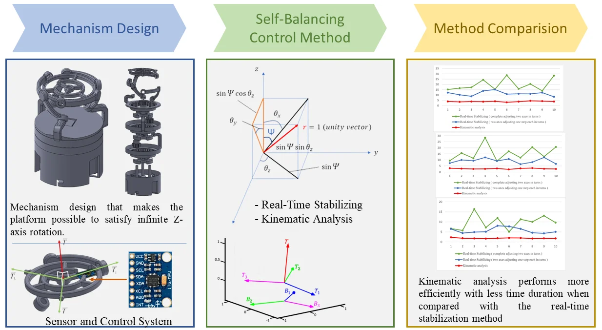
Abstract
Motion control platforms have various applications in the manufacturing and automation industries. Different literature provides multiple issues related to the kinematics and dynamics of self-guided robots for transportation regarding platform balancing. Self-balancing platforms are utilized in many deliveries, stabilization, and transportation systems, and they are especially well suited for outdoor activities when the ground surface is not flat or structured. This paper describes developing a control technique for a self-balancing platform using the 3-RCC spherical parallel manipulator. This mechanism was designed to support an AGV (Automated Guided Vehicle) for transporting and lifting heavy weights for industrial applications. The AGV carries a robotic arm on top for different tasks. When the AGV encounters a steep slope or a rough surface, the AGV tilts, and the robotic arm’s performance is significantly affected. So, this study gives a solution to avoid these circumstances with a novel approach for the platform’s self-balancing mechanism consisting of a 3-RCC spherical parallel manipulator. Real-time stabilization and kinematics analysis methods are used to achieve the self-balancing system of the platform. When both methods are observed through different tilting angles for automation stability, Kinematic analysis performs more efficiently with less time duration when compared with the real-time stabilization method.
Highlights
- Self-balancing platform designed for use by an automated guided vehicle (AGV) on steep slopes or rough surfaces.
- Self-balancing platform using 3-RCC spherical manipulator, which satisfies infinite Z-axis rotation with steady structure.
- Control methods (Real-time stabilization and Kinematic analysis) for platform stabilizing using IMU sensor.
1. Introduction
It is frequently challenging to calculate the kinematics of parallel systems with complete spatial mobility [1] in closed form. To reduce the complexity of the analytical problem while maintaining the benefits of closed-loop actuation, we have identified that researchers and industry are increasingly interested in small mobility mechanisms that can perform simple motions like pure rotations, pure translations, or planar displacements [2]. Parallel manipulators having three degrees of freedom can be classified into four groups. 3R (3-Rotation, also known as spherical parallel mechanism) [3], 3T (3-Translation) [4], 2R1T (2-Rotation and 1-Translation) [5] and 1R2T (1-Rotation and 2-Translation) [6]. Eventually, this will result in two similar tools mounted in series or working together in parallel to achieve a specific goal. Roll, pitch, and yaw are the three rotational degrees of freedom (DOF) [7] that can be handled by spherical parallel manipulators (SPM). As an alternative to current methods based on serial kinematic architecture [8], SPM can be considered when designing robotic wrists [9] due to their manipulator characteristics and high load-carrying capability. SPM provides different applications, which include medical tools [10, 11], moving platforms [12], advanced robotic systems [13], Tactile devices [14], and rehabilitation [15]. SPM was classified into four major groups based on the Lie group of displacements using the synthesis approach [16]. SPM in cylindrical motion (3-RCC, 3-CRC, 3-CCR), spherical motion (3-RRS, 3-RSR, 3-SRR) [9], parallel wrists with idle pairs (3-RRRPP, 3-RPRPR), and planar motion (3-RRG, 3-RGR, 3-GRR).
When an external force or torque is applied to one of a device’s RCC points, which are decoupled from the device’s operational compliance matrix, deformation only happens in the direction of the applied force or torque [7]. A compliance device that resembles the Stewart platform mechanism, which has been utilized as a flight simulator or a manipulator, is proposed by McCallion et al. [17]. Six prismatic actuators are swapped out for an equal number of linear springs. However, this device’s compliance matrix is not entirely diagonal (i.e., linked!), and an RCC point’s position cannot be changed. A better RCC device, called a “passive compliance device,” was also put out by him. It uses three rigid prismatic links and elastic membranes positioned between the links and platforms. Many translating similar machines [18] have been studied in past years, which show better performances, but they also have some demerits like a heavy moving platform, ineffective dynamic performances, etc. So, some new concepts have been developed for the whole family of machines with 3-RCC kinematics [19] to assess good performance and remove the demerits of previously identified mechanisms. The entire system’s stability can be enhanced by altering the position of the self-balancing system, which functions independently of the track chassis [20]. In this paper, the development of a prototype of a self-balancing platform is shown. This mechanism was originally designed to support a project consisting of an AGV. (Automated Guided Vehicle) that is a self-guided robot for transportation and lifting of heavy weights in warehouses and industries, with on top a robotic arm to accomplish such tasks. If the AGV faces a steep slope or a rough surface, the AGV will be tilted, and the performance of the robotic arm could get compromised. To avoid that, implementing a self-balancing [21] platform between the AGV and the robotic arm is a solution. The project’s goal is to demonstrate a platform that automatically maintains the horizontal position using balancing sensors [22] that control at all times. Different researchers use PID controller [23] and Arduino to develop the self-balancing controller, which helps the platform with several parameters along the vertical axis and provides the signals for controlling the values of the accelerometer and gyroscope sensors to determine the precise balance [24].
In this paper, a 3D-printed spherical mechanism [12] was used for testing and control. The mechanism is driven by the servos using a combination of three pinions and internal gears, each of them connected to one of the arms of the platform and capable of steering them in a constrained circular path; this also maintains the platform’s center at the same location regardless of how it rotates or tilts. Unlike standard gimbals, which may be used to correct tilt in each of its three components by positioning the motors on the platform’s axis, spherical parallel platforms do not follow conventional patterns. The movement of individual arms causes tilting of the platforms on different components at different rates and following specific paths.
The main contribution of this work is to design and control the self-balancing platform by using the 3-RCC spherical parallel manipulator, who always automatically stays horizontal all the time. The paper is organized in the following pattern. In part 2, a 3D design of the platform mechanism is developed using SolidWorks, and it is physically prepared using a 3D printer. In part 3, the self-balancing mechanism and control are explained. Finally, the control mechanism is calculated in section 4, and experimental results are shown. Then section 5 concludes the paper with a discussion and future aspects.
2. Mechanism designing
This section introduces two 3-RCC mechanisms mentioned in the study and new configurations created to meet the specifications. The novel configuration introduced three components: platform design, gearbox, and motor assembly.
2.1. Movements of platform
The 3-RCC structural is a parallel mechanism that connects an end effector to a fixed base via three structurally identical limbs. Each limb is a five-dimensional kinematic chain RCC, where R is a pair of revolute faces and C is a pair of cylinder faces. The three axes of the R and C pairings must converge at the fixed point O because they do not lie in a plane. The SPM center is a point that is invariant in a spherical motion. The commonly used 3-RCC spherical parallel mechanism is shown in Fig. 1, which satisfies most of the required tilting movements. However, manual control also plays a vital role besides the self-balancing mechanism. It was referenced as it could fulfill most tilting movements at first. It must also let the complete platform rotate along the z-axis while maintaining the same tilting angle. So, the primary 3-RCC spherical parallel mechanism doesn’t fit the need, as interference would occur due to the continuous rotation of the three motors.
Fig. 1Commonly used 3-RCC spherical parallel mechanism
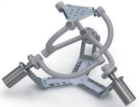
a) 3D Software model design
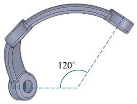
b) Metal-made spherical platform mechanism [3]
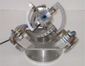
So, different designs were reviewed to complete the table rotation while maintaining the same tilting angle. There was a design with three motors in parallel at the bottom, which controlled the three gears set in tandem at the center, providing the complete rotation of the table. The proposed design shown in Fig. 2 provides a solution to the above issues and complies with our needs.
Fig. 2Spherical platform mechanism with three parallel motors
a) 3D software model design
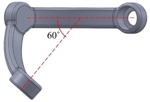
b) 3D printed spherical platform mechanism [12]
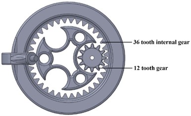
However, the system appears frail and unstable due to the design placing three isolated gears without further support. Then the modification in design was done by implementing three internal gears with the exchange of three gears in the middle as they rotate along the same axis. With these structures and tracks holding on to each other in the gearing arrangement, the mechanism remains stable, as shown in Fig. 3.
Fig. 3Internal gears arrangement for mechanism stability
2.2. Platform design
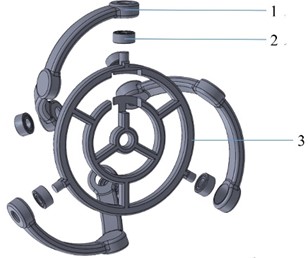
The platform design is shown in Fig. 4, which contains a platform with a diameter of 75 mm, three arms with a radius of 45mm attached in three directions, and bearings 685ZZ at both ends of the arms.
Fig. 4Platform part: (1) arm, (2) bearing 685ZZ, (3) platform
a) 3D software model design
b) 3D printed platform and arms
The arms are designed to encircle a sphere with a 45 mm radius to keep the platform’s center in place during all movements. As seen in Fig. 5, specific angles are specified to simplify the control calculations.
Fig. 5Arms designed with specific angles
a) Top view
b) Side view
2.3. Gearbox design and assembly
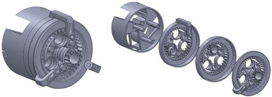
The gearbox is a critical part of the assembly whose design is shown in Fig. 6, which contains three levels, each attached with a bearing 6814ZZ, a stabilizing factor to stabilize the rotating gear, a gear synchronizing with the corresponding motor, and an internal gear attaching to the arm above. An additional bearing arrangement is installed with 6814ZZ bearings to smoothen the rotation, as illustrated in Fig. 7. Internals gears and the gears synchronizing the motors have a gear ratio of 1:3, which revolves the three motors with defined angles as shown in Fig. 8.
Fig. 6Components of Gearbox: (1-1) 1st bearing 6814ZZ, (1-2) 1st stabilizing part, (1-3) 1st gear, (1-4) 1st internal gear, (2-1) 2nd bearing 6814ZZ, (2-2) 2nd stabilizing part, (2-3) 2nd gear, (2-4) 2nd internal gear, (3-1) 3rd bearing 6814ZZ, (3-2) 3rd stabilizing part, (3-3) 3rd gear, (3-4) 3rd internal gear
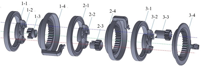
Fig. 7Bearings (6814ZZ) is set between gears to smoothen the rotation
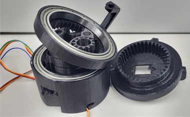
Fig. 8Relationship between gears synchronizing the motors and the internal gears
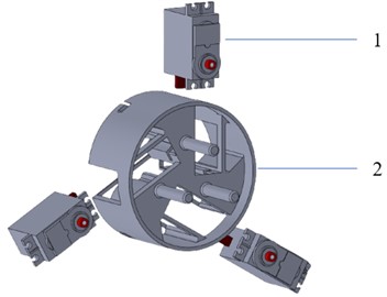
2.4. Motor assembly
Fig. 9 shows the motor assembly, which is installed in the container and contains three motors along with three columns attached to the three stabilizing parts above and a track to hold the bearing of the first level.
Fig. 9Motor set part: (1) motor MG-996R, (2) motor holding part
a) 3D Software model design
b) 3D Printed motor assembly
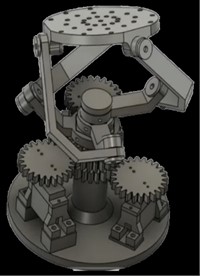
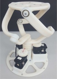
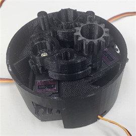
This section explained the designing of individual components, their mechanism, and their features. The complete design of the 3-RCC spherical parallel mechanism model was designed using CAD software (SolidWorks), as shown in Fig. 10(a). Then this design was fabricated using a 3D printer, as shown in Fig. 10(b). All experimental work, including model testing and control, was done using this 3D-printed spherical platform mechanism. The mechanism can be separated into three parts: platform, gearbox, and motor set. The different features and components of the 3-RCC spherical parallel mechanism model are explained below.
Fig. 10Complete spherical parallel mechanism design
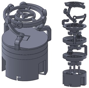
a) 3D Software model design
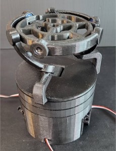
b) 3D Printed spherical platform mechanism
3. Self-balancing system
This section introduces the sensor for motor control and how it features and functions in the mechanism of the proposed design.
3.1. Balancing sensor
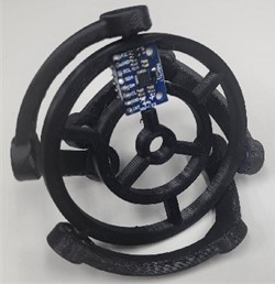
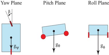
A sensor is required to measure the platform’s tilt or position in three dimensions concerning the ground necessary to maintain the platform’s balance for balancing, implementing IMU (Inertia Measurement Unit) sensors that communicate with the Arduino using an I2C Bus Protocol. In this proposed design, the sensor MPU-650 is shown in Fig. 11(a), which was adopted due to its accuracy, reliability, and low pricing among all IMU Arduino sensors. It is a six-DOF (Degree of Freedom) sensor that combines a 3-axis gyroscope and a 3-axis accelerometer. The data collected from the sensor are the pitch, roll, and yaw, as shown in Fig. 11(b), which are the angles of motion in , , and coordinates and depend on the gravitational force.
Fig. 11a) MPU-6050, b) sensor’s degree of freedom
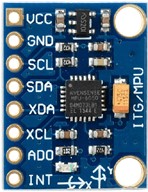
a) MPU-6050
b) The six degrees of freedom
3.2. Data collection
In the first trial, the raw data was collected by the Arduino processor and displayed on the serial monitor. It was noticed that the data became less accurate and very noisy after some time. Along with the effects of gravity on the accelerometer, external forces contributed to this, which affected the precision of orientation angles. Those external forces are caused by the manipulation and movement of the sensor and add noise to the output data. The accelerometer provided noise to the data in the short term but was very accurate in the long term. However, whereas the gyroscope provides accurate data on orientation changes in the short term, the combination of data causes a drift over longer time scales.
Fig. 12Circuit Schematics with DMP
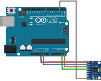
It was found that the MPU-6050 sensor comes with a hardware buffer on the chip, and with a specific code, it performs data conversion. It also filters and combines a portion of the data collected from the gyroscope and another from the accelerometer to eliminate the noise and preserve precision along with the time in a process called the Digital Motion Processor (DMP). For this method, an extra wire connecting the int pin in the sensor to the pin 2 digital input/output in the Arduino is the main change in the circuit schematics, as shown in Fig. 12. Data gathered from a still gyroscope will not gradually rise or fall when DMP is present. Additionally, after 10 repetitions of circulation movement, accumulated errors were reduced to less than 0.05 degrees. However, in software, a code from an open-source library called I2Cdevlib to retrieve the data was applied and also available on the internet for downloading.
3.3. Motor control
To minimize the platform size and have accurate angle control for each arm, we set three MG996R servo motors at the bottom to control each gear inside. The angles and steps required to rotate can be done precisely, but because there is no linear control for the rotating speed, the control technique below couldn’t make the three motors complete their tasks simultaneously.
4. Control methods for self-balancing mechanism
To achieve self-balancing, two essential methods were established: real-time stabilizing and kinematic analysis. For preprocessing calculation, the following data has to fetch from the sensor, which is done by placing MPU-6050 in the middle of the platform. So for measuring and calculating the tilting angles at each period in pitch, roll, and yaw, three directions showing , and each is displayed through a window screen as shown in Fig. 13.
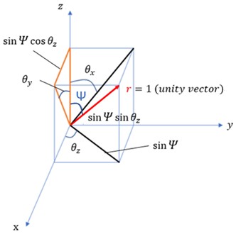
The relationship between , , and is shown in Fig. 14. The value of and defining vectors is stated in the Eq. (1) and (2):
Fig. 13Angles calculated by data measured using MPU-6050
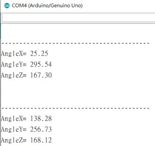
Fig. 14Relationship between θx, θy, θz and ψ
We figured out the first method to control the balancing with the data above.
4.1. Real-time stabilizing
Initially, classify the tilting directions into 1°, –1°, 1° and –1°, in which all kinds of situations are combined by two of the above. A generalized connection for the direction of controlling two motors is described in the Table 1 based on direct observation of the motor motions and their effects. (Controlling three motors at once will result in a more complicated tilting scenario and will be ineffective for stabilizing). The relationship between motors rotating degree and the degree to which they differ for and is nonlinear. With this relationship, the adjustment of the platform can be made by moving the required motor movements at every cycle. The gyroscope will provide the current data while the motors keep pushing the platform toward horizontal balance until the defined balance conditions are satisfied, realizing the adjustment in real time.
Table 1Relationship between motor motion and effect on tilting angles
Motor 1 | Motor 2 | Motor 3 | Main effect |
Reverse | Reverse | increase | |
Forward | Reverse | decrease | |
Forward | Reverse | increase | |
Reverse | Reverse | decrease |
4.1.1. Complete adjusting two axes in turns
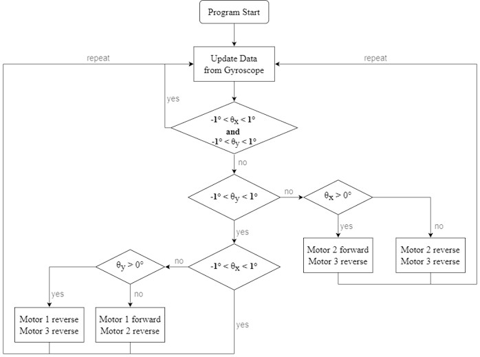
In this method, a condition is determined where –1° 1° and –1° 1° met at the same time if it is balanced. If the data from the gyroscope shows that the platform is not balanced, then we check and adjust -axis till –1° 1° is satisfied, then the movement is adjusted on -axis till –1° 1° is satisfied, as illustrated in Fig. 15.
Fig. 15Flow chart of real-time stabilizing when adjusting two axes in turns
However, it was found that the effects shown in Table 2 are easily observed effects, which may attach with random effects on the other two axes. Besides, the incidental effects can also be different in detail when the three arms are in different orders of position. Consequently, for instance, when the platform is only tilted in the positive -axis, we can not only control motor-2 in a forward direction and motor-3 in a reverse direction. In order to fix the to be tilted, then will also in tilting progress.
Measuring responding time in seconds for having the platform back to the balancing position by tilting the platform with angles 30°, 20° and 10° in random directions every ten rounds, whose results are shown in Table 2, (Range = (maximum + minimum) / 2 ± (maximum-minimum) / 2).
Table 2Time spent to balance the platform (second)
#1 | #2 | #3 | #4 | #5 | #6 | #7 | #8 | #9 | #10 | Range | AVG | |
30° | 15.23 | 16.55 | 17.19 | 24.35 | 15.48 | 28.70 | 15.89 | 20.44 | 13.97 | 28.27 | 21.34 ± 7.3 | 19.61 |
20° | 9.35 | 15.64 | 11.37 | 28.45 | 9.04 | 17.16 | 11.86 | 20.51 | 12.76 | 20.71 | 18.75 ± 9.7 | 15.69 |
10° | 6.67 | 5.74 | 16.41 | 7.22 | 11.93 | 5.11 | 11.27 | 10.03 | 13.10 | 9.66 | 10.76 ± 5.7 | 9.71 |
In the above results, the responding time is much longer than expected due to adjusting the and -axis, which kept functioning in all the turns until their conditions were satisfied. Besides, the range is also too unsteady. So, another method of two axes adjusting one step each in turns is analyzed for real-time stabilizing control.
4.1.2. Two axes adjusting one step each in turns
Rather than modifying the -axis until the requirement is fulfilled, the motor has to be controlled one step and then move on to the -axis to ensure that incidental effects in each motion and may be corrected instantly. The flowchart of this method is shown in Fig. 16.
Fig. 16Flow chart of real-time stabilizing when two axes adjust one step each in turns
Responding time of this method has been measured, and the results are shown in Table 3.
Table 3Time spent to balance the platform (second)
#1 | #2 | #3 | #4 | #5 | #6 | #7 | #8 | #9 | #10 | Range | AVG | |
30° | 12.27 | 10.21 | 8.79 | 13.90 | 15.15 | 10.88 | 11.16 | 11.06 | 12.29 | 8.32 | 11.74 ± 3.4 | 11.40 |
20° | 7.32 | 9.94 | 9.31 | 12.04 | 9.13 | 10.75 | 6.42 | 8.14 | 12.08 | 6.71 | 9.25 ± 2.8 | 9.18 |
10° | 6.52 | 4.41 | 4.92 | 5.12 | 8.09 | 7.77 | 6.54 | 4.63 | 4.29 | 5.06 | 6.19 ± 1.9 | 5.74 |
In this turn, the average responding time is much shorter, and the range is narrowed as compared to an earlier one. Still, such responding time is not ideal enough. Observing the stabilizing process, it appears that the limit speed of the motors is too slow, and too much time is lost correcting the and -axis in turns rather than directly fixing the tilted angle in its direction.
4.2. Kinematic analysis
In this method, the relationship between the normal vector of the platform and the angle movements of the three motors is directly considered.
4.2.1. Platform vectors
Considering Fig. 17, the normal vector of the platform (set length as that equals the other vectors for convenience) and aligned to the sensor MPU-6050:
With the relationship of the Eqs. (3) and (4), the value of and is described by the Eqs. (5), (6) and (7):
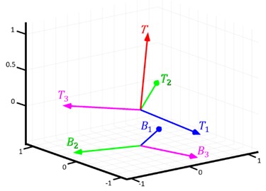
Fig. 17Vectors T⃑ , T1⃑ , T2⃑, T3⃑
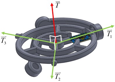
Fig. 18Relationships needed to solve
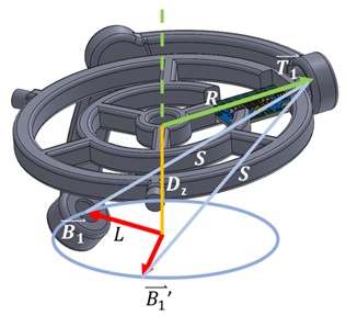
Then with the Eqs. (8), (9), (10), the spot coordinate of connecting to is determined. The angle position can be determined with the positive and negative values of and from Fig. 18. There shall be two solutions as there are two spots that satisfy the conditions ( and ). For finding the correct solution, drawing of simulated coordinates has to be drawn by calculating the two solutions as shown in Fig. 19. We could confirm which solution matches reality by observing their position in space. Similarly, the same method will apply to solving and :
Determination of rotation of motors in different tilting angle in various situations has been be identified with the relationship between the gyroscope data (, and ) and the angles’ motions of three motors (, and ). For example, when the gyroscope provides current data , and as 20°, –15° and 45°, Arduino will calculate the angles , and corresponding to the condition having the platform tilting to –20°, 15° and 45°. After rotating the motors with the angles above, the platform will return to a horizontal balancing position.
Fig. 19Vectors calculated by data received from MPU-6050
4.2.2. Calculation of kinematic analysis
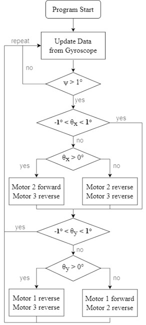
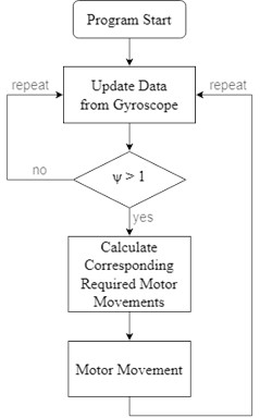
The flow chart, as shown in Fig. 20 for the calculation of kinematic analysis, states the completion of movement is possible when it satisfies . When the movement is completed, the platform will be in its balancing position.
Fig. 20Flow chart of kinematic analysis method
Measurement is taken for the responding time in seconds when the platform has to balance with the tilting angle 30°, 20° and 10° in random directions every ten rounds. The result of this analysis is shown in Table 4.
Table 4Time spent to balance the platform (second)
#1 | #2 | #3 | #4 | #5 | #6 | #7 | #8 | #9 | #10 | Range | AVG | |
30° | 3.95 | 3.52 | 3.87 | 3.69 | 4.12 | 3.15 | 3.76 | 4.49 | 4.28 | 3.86 | 3.82 ± 6.7 | 3.87 |
20° | 3.11 | 2.78 | 2.50 | 2.57 | 2.94 | 2.17 | 2.97 | 3.26 | 2.61 | 2.48 | 2.72 ± 5.4 | 2.74 |
10° | 2.32 | 1.86 | 1.75 | 1.69 | 1.84 | 2.03 | 1.98 | 1.73 | 1.81 | 1.76 | 2.00 ± 3.2 | 1.88 |
This control method is faster not only because the inclinations of the and axes are considered and processed together but also because the rotation of the axis is preserved (platform balancing doesn’t need to consider direction). However, this method of controlling the rotation angle of each servo motor has the following two disadvantages:
a) The required rotation angle of each motor is different, so they can’t complete the necessary rotations with their same limit speed. To avoid this, the speed of the three motors should be distributed in equal proportion to the required rotation angle (the motor with the most significant angle of rotation needed is controlled at the highest rotational speed). It is the best way to complete the rotation of all motors at the same time. However, linear, rotational speed adjustment is not easy on servo motors.
b) It still takes several seconds to reach equilibrium, but the gyroscope data will not be updated until the motor rotates to the specified angle. Therefore, if the platform is tilted in other directions during the required rotation, the motor will still complete the original rotation command before charging the new correction angle and cannot respond promptly to the tilting condition.
5. Results analysis
After the experimental analysis was done for both methods, the comparative results are shown in Fig. 21. After all the experiments for different tilting angles by all the methods, the experimental findings of the procedure of completely adjusting two axes in turns differ significantly among them. It has been observed that using this approach, the efficiency of a single axis balancing with the same angle in various directions varies, resulting in a short variable time to attain stability in each turn. When it comes to the results using two axes adjusting one step each in turns, it has an immediate difference from the method of kinematic analysis, which results in faster operation along with control balancing of the platform. It is clear from the comparison that the method of kinematic analysis is the most effective control approach for balancing the platform.
Fig. 21Comparison between results of methods above
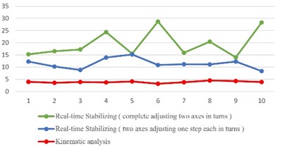
a) = 30 degrees
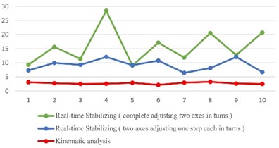
b) = 20 degrees
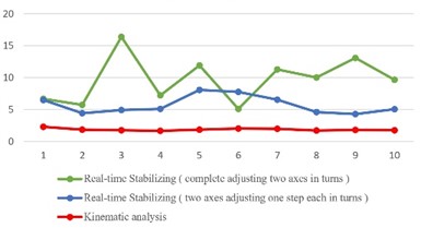
c) = 10 degrees
6. Conclusions
This study provides automated platform stabilization using a system similar to the 3-RCC structure, which can rotate on the axis at the same tilting angle. Different tilting angles with automation stability have been observed with a tilting angle of 30 degrees; the automatic stabilization efficiency is 5 seconds, 3.5 seconds at 20 degrees, and 3 seconds at 10 degrees. In a conventional model of three coaxial gears, instability occurs due to isolated gears. As a result, the mechanism design has been modified, including internal gears with bearings, increasing the system’s stability. To minimize torque, the arms that support the platform has been reduced to improve the platform’s stability. The varied placements of the three arms complicate the interaction between motor actions and how they tilt the platform in terms of automatic stability management. It is observed that the real-time stabilization method is inefficient compared to kinematic analysis. Kinematic analysis performs well with less time duration; in this case, the platform does not require direction. However, some restrictions are due to accurate angle control and rotation over 360 degrees achieved by servo motors which will be a future scope of the study. Also, stepper motors can achieve stabilization more efficiently and accurately despite taking up more space in future studies. In further analysis, by enhancing the devices currently in use, it may be possible to make the kinematic analysis approach responsive to sudden changes in tilting direction during stabilization and to reduce the reacting time to under one second.
References
-
F. Behi, “Kinematic analysis for a six-degree-of-freedom 3-PRPS parallel mechanism,” IEEE Journal on Robotics and Automation, Vol. 4, No. 5, pp. 561–565, 1988, https://doi.org/10.1109/56.20442
-
S. Briot and I. A. Bonev, “Accuracy analysis of 3-DOF planar parallel robots,” Mechanism and Machine Theory, Vol. 43, No. 4, pp. 445–458, Apr. 2008, https://doi.org/10.1016/j.mechmachtheory.2007.04.002
-
S. Bai, X. Li, and J. Angeles, “A review of spherical motion generation using either spherical parallel manipulators or spherical motors,” Mechanism and Machine Theory, Vol. 140, pp. 377–388, Oct. 2019, https://doi.org/10.1016/j.mechmachtheory.2019.06.012
-
L.-W. Tsai, G. C. Walsh, and R. E. Stamper, “Kinematics of a novel three DOF translational platform,” in Proceedings of IEEE International Conference on Robotics and Automation, Vol. 4, pp. 3446–3451, 1996, https://doi.org/10.1109/robot.1996.509237
-
D. Wang, L. Wang, J. Wu, and H. Ye, “An experimental study on the dynamics calibration of a 3-DOF parallel tool head,” IEEE/ASME Transactions on Mechatronics, Vol. 24, No. 6, pp. 2931–2941, Dec. 2019, https://doi.org/10.1109/tmech.2019.2942622
-
X.-J. Liu, J. Wang, and G. Pritschow, “A new family of spatial 3-DoF fully-parallel manipulators with high rotational capability,” Mechanism and Machine Theory, Vol. 40, No. 4, pp. 475–494, Apr. 2005, https://doi.org/10.1016/j.mechmachtheory.2004.10.001
-
W.-K. Kim, B.-J. Yi, and W. Cho, “RCC characteristics of planar/spherical three degree-of-freedom parallel mechanisms with joint compliances,” Journal of Mechanical Design, Vol. 122, No. 1, pp. 10–16, 2000, https://doi.org/doi.org/10.1115/1.533541
-
N. M. Bajaj, A. J. Spiers, and A. M. Dollar, “State of the art in artificial wrists: A review of prosthetic and robotic wrist design,” IEEE Transactions on Robotics, Vol. 35, No. 1, pp. 261–277, Feb. 2019, https://doi.org/10.1109/tro.2018.2865890
-
V. V. Patel and A. M. Dollar, “Robot hand based on a spherical parallel mechanism for within-hand rotations about a fixed point,” in 2021 IEEE/RSJ International Conference on Intelligent Robots and Systems (IROS), pp. 709–716, Sep. 2021, https://doi.org/10.1109/iros51168.2021.9636704
-
T. Li and S. Payandeh, “Design of spherical parallel mechanisms for application to laparoscopic surgery,” Robotica, Vol. 20, No. 2, pp. 133–138, Mar. 2002, https://doi.org/10.1017/s0263574701003873
-
A. Chaker, A. Mlika, M. A. Laribi, L. Romdhane, and S. Zeghloul, “Synthesis of spherical parallel manipulator for dexterous medical task,” Frontiers of Mechanical Engineering, Vol. 7, No. 2, pp. 150–162, Jun. 2012, https://doi.org/10.1007/s11465-012-0325-4
-
I. Tursynbek, A. Niyetkaliye, and A. Shintemirov, “Computation of unique kinematic solutions of a spherical parallel manipulator with coaxial input shafts,” in 2019 IEEE 15th International Conference on Automation Science and Engineering (CASE), pp. 1524–1531, Aug. 2019, https://doi.org/10.1109/coase.2019.8843090
-
S. Sadeqi, S. P. Bourgeois, E. J. Park, and S. Arzanpour, “Design and performance analysis of a 3-RRR spherical parallel manipulator for hip exoskeleton applications,” Journal of Rehabilitation and Assistive Technologies Engineering, Vol. 4, p. 205566831769759, Jan. 2017, https://doi.org/10.1177/2055668317697596
-
H. Saafi, M. A. Laribi, and S. Zeghloul, “Redundantly actuated 3-RRR spherical parallel manipulator used as a haptic device: improving dexterity and eliminating singularity,” Robotica, Vol. 33, No. 5, pp. 1113–1130, Jun. 2015, https://doi.org/10.1017/s0263574714001751
-
M. Malosio, S. P. Negri, N. Pedrocchi, F. Vicentini, M. Caimmi, and L. Molinari Tosatti, “A spherical parallel three degrees-of-freedom robot for ankle-foot neuro-rehabilitation,” in 2012 34th Annual International Conference of the IEEE Engineering in Medicine and Biology Society (EMBC), pp. 3356–3359, Aug. 2012, https://doi.org/10.1109/embc.2012.6346684
-
M. Karouia and J. M. Hervé, “A family of novel orientational 3-dof parallel robots,” in Romansy 14, Vienna: Springer Vienna, 2002, pp. 359–368, https://doi.org/10.1007/978-3-7091-2552-6_38
-
H. Mccallion, K. V. Alexander, and D. T. Pham, “Aids for automatic assembly,” in Proceedings of the First International Conference on Assembly Automation, pp. 313–323, 1980, https://doi.org/10.1007/978-94-011-6403-0_8
-
M. Callegari, “Design and prototyping of a spherical parallel machine based on 3-CPU kinematics,” in Parallel Manipulators, New Developments, I-Tech Education and Publishing, 2008, pp. 171–198, https://doi.org/10.5772/5368
-
M. Callegari and M.-C. Palpacelli, “Kinematics and optimization of the translating 3-CCR/3-RCC parallel mechanisms,” in Advances in robot kinematics, Springer, 2006, pp. 423–432, https://doi.org/10.1007/978-1-4020-4941-5_46
-
F. Ye and Y. Su, “Research on modeling and control algorithm of self-balancing platform of spraying robot,” in Journal of Physics: Conference Series, Vol. 2437, No. 1, p. 012109, Jan. 2023, https://doi.org/10.1088/1742-6596/2437/1/012109
-
S. He and X. Wen, “Six degree-of-freedom self-balancing platform design based on EtherCAT,” Nanjing Xinxi Gongcheng Daxue Xuebao, Vol. 12, No. 3, pp. 384–389, 2020, https://doi.org/10.13878/j.cnki.jnuist.2020.03.018
-
J. Cerezo, E. Morales, and J. Plaza, “Control system in open-source FPGA for a self-balancing robot,” Electronics, Vol. 8, No. 2, p. 198, Feb. 2019, https://doi.org/10.3390/electronics8020198
-
E. Ataç, K. Yildiz, and E. E. Ülkü, “Use of PID control during education in reinforcement learning on two wheel balance robot,” Gazi Üniversitesi Fen Bilimleri Dergisi Part C: Tasarım ve Teknoloji, Vol. 9, No. 4, pp. 597–607, Nov. 2021, https://doi.org/10.29109/gujsc.955562
-
C. N. Savithri, R. S. Roopesh, N. Lavanya Devi, P. Shanthakumar, and P. Thirumurugan, “Self-balancing robot using arduino and PID controller,” in Lecture Notes in Electrical Engineering, Singapore: Springer Nature Singapore, 2023, pp. 201–208, https://doi.org/10.1007/978-981-19-7169-3_18
About this article

The authors have not disclosed any funding.
The datasets generated during and/or analyzed during the current study are available from the corresponding author on reasonable request.
Yen Jung Chen: formal analysis, investigation, validation; Wei Cheng Tung: development of methodology; Wei Rui Lee: methodology, software; Brijesh Patel: writing, editing; Vytautas Bučinskas: supervision; Modris Greitans: supervision; Po Ting Lin: conceptualization, supervision, resources.
The authors declare that they have no conflict of interest.
