Abstract
With the rapid developments of Industry 4.0 and Smart Manufacturing, customized manufacturing has been becoming greatly needed. Meanwhile, the challenge of production automation has become more bigger, especially for the automation of moving, picking, placing and manipulating objects. Many researchers have begun to work on Autonomous Ground Vehicles (AGVs). Most AGVs were utilized to carry middle or small objects, as the high-payload AGVs were rarely developed. This paper focused on the design of a High-Payload Mecanum-Wheel Ground Vehicle (MWGV), which was 1.7 m wide and 2.04 m long. The weight of the vehicle was 740 kg and it was able to carry the payload as its own weight (i.e. around 7,300 N). The safety factor of the structural strength was greater than 1.66 and the safety factor of the axial design was at least 6.24. The vehicle was designed to carry 150-kg weight with a reach of 1.375 m without falling. The design of Mecanum wheels provided great flexibility on movement with small rotational radius. Mathematical descriptions about how Mecanum wheels were controlled was also introduced in this paper. Furthermore, the mechatronics and software integrations were demonstrated. The final experimental results showed the developed MWGV was able to perform the desired movement properly.
Highlights
- High-Payload Mobile Manipulation
- Mecanum-Wheel Ground Vehicle (MWGV)
- Mechanical design and stress analysis
1. Introduction
Autonomous ground vehicles (AGVs) [1-9] have been developed for industrial applications and began to play important roles in the development of Industry 4.0 and Smart Manufacturing. AGV could be used for carrying and moving items in the factory replacing some of the labor-intensive human missions. On the other hand, linear (or curved) guideways have been widely used for the similar purposes and functions as AGV. Linear guideways could provide high payload capability but the moving trajectories are usually fixed. Fig. 1 shows a robot arm system with linear guideway that could be moving along the given linear trajectory freely and picking/placing items at the surrounding elements. The Erowa ERG150L robot arm could be moving in a 30 m long linear guideway and reach out for 1.375 m long to carry a 150 kg item without falling over. The linear layout could be customized based on the needs but rearranging the layout could take some time. Rearrangement of the layout won’t happen too often; therefore, the robot arm system with linear guideway is not as flexible as robot arm on an AGV, which can move freely inside the factory.
Table 1 shows a list of commercial AGV. There are two kinds of AGVs: the first kind is for carrying heavy objects and the other kind is designed for robot arm manipulation. As shown in Table 1, Symbridge MiR1000 could carry 1000-kg payload as the iAmech 2D Bar Code Guide AGV could carry 300 kg payload. Prefactortech MR-VT6 has a robot arm with a 6 kg payload and GreenTrans MR-100 carries a robot arm with 12 kg payload. The AGV with robot arm usually has a lower capability of carrying weights because its center of mass is typically higher than the AGV without robot arm and lower payload prevents the chance of falling over. Therefore, AGV with a high-payload robot arm is less common in the market. This paper presents a AGV that is designed for carrying a high-payload robot arm. The goal of this design is to manipulate heavy objects in a mobile system that could freely move (and rotate) inside a smart factory.
Fig. 1Erowa robot arm system with linear guideway [10]
![Erowa robot arm system with linear guideway [10]](https://static-01.extrica.com/articles/22133/22133-img1.jpg)
Table 1Comparison of commercial AGVs
Company | Symbridge group | iAmech | Prefactortech | GreenTrans |
Product name | MiR1000 | 2D Bar Code Guide AGV | MR-VT6 | MR-100 |
Carrying payload | 1000 kg | 300 kg | 70 kg | 100 kg |
Robot arm | No | No | Yes | Yes |
Robot arm payload | – | – | 6 kg | 12 kg |
Size of vehicle | Length 1350 mm Width 920 mm Height 320 mm | Length 850 mm Width 650 mm Height 305 mm | Length 1154 mm Width 654 mm Height 700 mm | Length 1154 mm Width 654 mm Height 700 mm |
Weight of vehicle | 231 kg | 110 kg | 230 kg | 242 kg |
2. Mechanical design of the MWGV
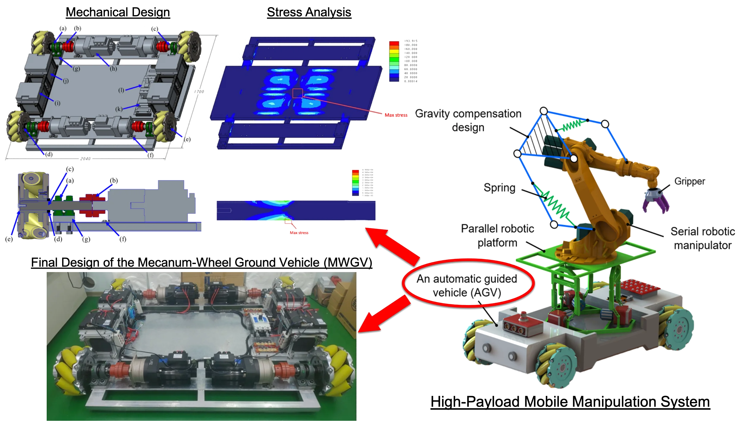
In this paper, the design of a high-payload Mecanum-Wheel Ground Vehicle (MWGV) [11, 12] is presented. The goal of the proposed MWGV is to integrate with a parallel platform, a high-payload robot arm, and a gravity compensation design, as shown in Fig. 2. The parallel platform ensures that the coordinate system of the robot arm above the platform aligns with the direction of gravity even when the ground is not completely flat. Although the gravity compensation system increases the external loads applied to some of the axis motors in the robot arm, it enhances the capability of manipulating the objects that are heavier than the allowable payload. The mechanical design and analysis of the MWGV will be introduced in this section.
2.1. Mechanical design of the chassis and the axle systems
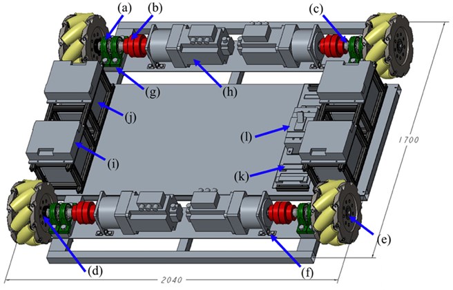
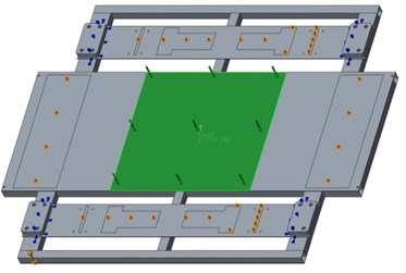
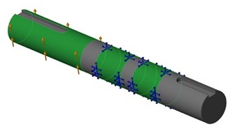
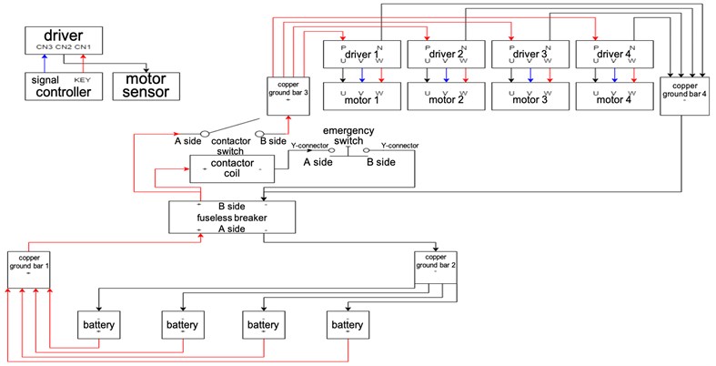
Fig. 3 shows the mechanical design of the proposed MWGV, which is 1.7 m in length, 2.04 m in width and 0.4 m in height. The length of the vehicle (from front to back) is shorter than the width (from left to right) so that robot manipulation could be done at the frontal direction of the vehicle. The total weight of the MWGV is 740 kg, which is heavy enough so that the robot arm above it could carry a 150-kg object in a reach of 1.375 m without falling over. The vehicle is composed of a chassis, 4 axle systems and other circuit components. The axle system, as shown in Fig. 4, is powered by the battery, shown in Fig. 3 (j). A driver, shown in Fig. 3 (i), transmits motor control signals to one motor, that is connected to a reducer, as shown in Fig. 3 (h). The motor shaft is connected to a wheel axle, Fig. 4 (c), using a set of coupling rubbers, Fig. 4 (b). The wheel axle is carried by two ball bearings, as shown in Fig. 4 (a). One Mecanum wheel is fixed to the axle using a fixing ring, as shown in Fig. 4 (d), and tightened with a bolt and a washer, as shown in Fig. 4 (e), at the edge of the axle. The batteries are connected to a circuit system with multiple copper ground bars, as shown in Fig. 3 (k), and a fuesless breaker, as shown in Fig. 3 (l).
Fig. 2Design of a high-payload ground vehicle with robot manipulation for industrial applications
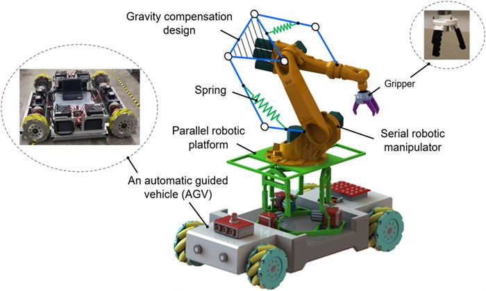
Fig. 3The mechanical design of the MWGV: (a) ball bearing, (b) coupling rubber, (c) axle, (d) fixing ring, (e) washer, (f) L-shaped bracket, (g) metal plate, (h) motor and reducer, (i) driver, (j) battery, (k) copper ground bar, (l) fuseless breaker
The commercially available mechanical parts include the bearings, coupling rubbers, motors, and reducers. On the other hand, the chassis and axles were designed based on stress analyses and evaluations of safety factors. Fig. 5 shows the Finite Element Analysis (FEA) of the chassis design. The chassis, that is made of S45C steel, carries a uniformly distributed load of 7300 N at the center (around same as the vehicle’s own weight), as shown in Fig. 5 (a). Each battery applies an external load of 200 N (totally 800 N) to the chassis and each motor system applies a load of 500 N (totally 2000 N). The FEA results are shown in Table 2. The maximum von Mises stress was found at the center of the chassis, as shown in Fig. 5 (b), and its magnitude was 193.92 MPa. Based on Maximum Distortion Energy (MDE) Theory [13], the safety factor could be calculated by maximum von Mises stress over the yielding strength, 343.23 MPa and it was 1.77, as shown in Table 3. The maximum shear stress was found to be 103.50 MPa. Based on Maximum Shear Stress (MSS) Theory [13], safety factor (i.e. maximum shear stress divided by two times yielding strength) was 1.66. The maximum displacement of the chassis was 3.03 mm. Fig. 6 shows the FEA of the wheel axle, that is also made of S45C steel. Each axle carries one fourth of the sum of the vehicle weight and the payload placed at the center of the chassis, i.e. 3626 N. The stress concentration was found near the edge of the bearing, as shown in Fig. 6 (b). The maximum von Mises stress and shear stresses in the axle were found to be 49.04 and 27.52 MPa, respectively. Therefore, the safety factors for the static load condition were 7.00 (based on MDE) and 6.24 (based on MSS), respectively. Wheel axles of AGV do not rotate as fast and frequently as other rotary systems so it’s not essential to perform fatigue analysis due to fluctuating loads.
Fig. 4The cross-section view of the axle design: (a) ball bearing, (b) coupling rubber, (c) axle, (d) fixing ring, (e) washer, (f) L-shaped bracket, (g) metal plate
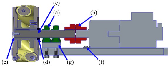
Fig. 5FEA of the chassis
a) Load condition
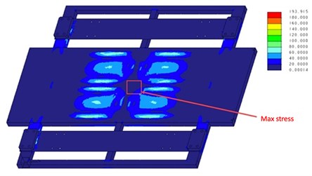
b) Von Mises stress distribution
Fig. 6FEA of the axle
a) Load condition
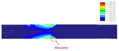
b) Von Mises stress distribution
Table 2FEA results
Simulation results | Stress in chassis | Stress in axle |
Max von Mises stress | 193.92 MPa | 49.04 MPa |
Max shear stress | 103.50 MPa | 27.52 MPa |
Max displacement | 3.03 mm | 0.06 mm |
Table 3Safety factors of chassis and axle
Safety factor models | Safety factors of chassis | Safety factors of axle |
MDE | 1.77 | 7.00 |
MSS | 1.66 | 6.24 |
2.2. Design of the Mecanum wheels
A Mecanum wheel is known to have multiple rollers around its perimeter, as shown in Fig. 7. The diameter of each wheel is 375 mm and the weight is 71 kg. The rotational axis of the roller as a 45-degree twist against the wheel axis. The friction force between the roller and the ground is not along the frontal direction of the vehicle; therefore, the transverse part of the friction force allows the vehicle to move from left to right. The separate control of each Mecanum wheel allows the vehicle to move and rotate freely.
Fig. 7Twist angle between each roller and the rotational axis of the Mecanum wheel
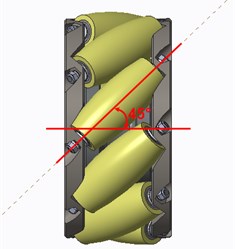
Fig. 8Arrangement of the four Mecanum wheels
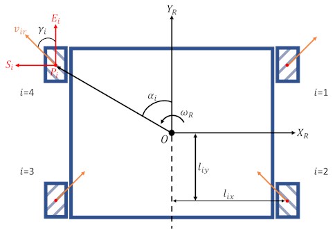
The layout of the Mecanum wheels is shown in Fig. 8. is the center of the vehicle. and are the transverse and front directions of the vehicle, respectively. The velocity vectors of the vehicle along the and directions are given as and , respectively. The angular velocity of the vehicle is . stands for the index of the Mecanum wheel. is the center of the th wheel. The distance from to is given as . The horizontal and vertical distances from to are given as and , respectively. The angle from to is denoted as . More details about the wheel could be seen in Fig. 9. The velocity vector of the roller of the th wheel is given as . and represent the axial and transverse direction of the wheel, respectively. The components of along the directions of and are given as and , respectively. The angle between and is . The radius of the tire is and the radius of the roller is . The angle between the wheel coordinate and the vehicle coordinate is . The angular velocity and moving speed of the th wheel are denoted as and , respectively.
Based on the velocity analysis derived by Taheri, et al. [14], the separate control of angular velocity of each Mecanum wheel could be determined with respect to the desired , and , that is given by Eq. (1) where the parameters of the vehicle are given in Table 4. Rearranging Eq. (1), the Eq. (2) could be derived where the moving speed and angular velocity of the vehicle could be determined by each wheel’s angular velocity:
Fig. 9Angular velocity analysis of the Mecanum wheel
Table 4Design parameters in the MWGV
1 | 2 | 3 | 4 | |
(rad) | 1 | –1 | ||
(rad) | ||||
(rad) | ||||
(m) | 0.935 | 0.935 | 0.935 | 0.935 |
(m) | 0.6 | 0.6 | 0.6 | 0.6 |
(m) | 1.111 | 1.111 | 1.111 | 1.111 |
(m) | 0.1875 | 0.1875 | 0.1875 | 0.1875 |
3. Power and mechatronics of the MWGV
To have appropriate selections of the motors, a free-body diagram in Fig. 10 is used to analyze the required power to drive the vehicle. The driving force should be greater than the sum of rolling friction force , air drag force , gravity force along the slope and inertia force , which are respectively given in Eqs. (3) to (6):
In Eqs. (3) to (6), is the rolling friction coefficient; is the total mass of vehicle and payload; is the gravitational acceleration; is the incline angle of the slope; is air density; is drag coefficient; is the projected frontal area of vehicle; and are the velocity and acceleration of the vehicle, respectively; is the added mass rate, which allows the designer to estimate how much inertia the driving force needs to carry. The required driving force could be computed as:
where , , and stand for the output torque of motor, the reduction ratio, the efficiency of power transmission, and the wheel radius, respectively. Considering the parameters shown in Table 5, the resultant forces were determined and listed in Table 6. The incline angle of the slope was considered to be zero in the general model shown in Fig. 10 to meet the most common factory conditions.
Fig. 10Free-body diagram of ground vehicle moving on a slope
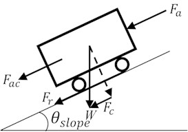
Table 5Design parameters in the power analysis of MWGV
1480 kg (vehicle weight plus additional payload) | |
g | 9.81 m/s2 |
0.05 | |
0.125 kg/m3 | |
1.15 | |
1.02 m2 | |
1.96 m/s | |
0° | |
0.981 m/s2 | |
0.07 | |
0.9 | |
0.1875 m |
Table 6Resultant forces of the power analysis
725.94 N | |
0.28 N | |
0 N | |
1,553.51 N | |
2,279.73 N | |
474.94 Nm |
Based on the power analysis, each motor needs to produce a torque of 118.74 Nm. The brushless motor BM-3700E by Adlee Powertronic Company, Ltd. was chosen and connected to a 1:10 reducer MF180X. A rated torque of 119.64 Nm (i.e. one fourth of times ) could be produced as the MWGV carries a payload of 740 kg.
Fig. 11 shows the circuit system to power and control the motors. Each motor system requires a driving power of 3700W in 48V. Four 48V30AH rechargeable lithium batteries by Ty-Dynamic Company, Ltd. are connected to the copper ground bars 1 and 2 in parallel. The copper ground bars 1 and 2 are connected to the fuseless breaker with a safety mechanism based on a contactor and an emergency switch (i.e. normal close). The contactor transmits power to the drivers and the motors through the connection of copper ground bar 3. As the emergency switch is pushed, the contactor coil opens the contactor switch and stops providing power to the motors.
Fig. 11Circuit system for motor control
4. Experimental results
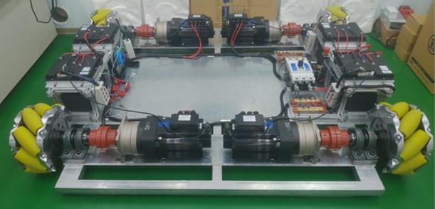
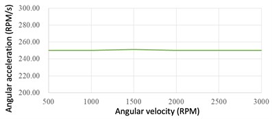
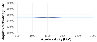
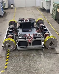
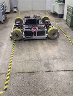
The final assembly of the MWGV could be seen in Fig. 12. A series of speed tests for each motor were executed to ensure the vehicle could be properly controlled. First, each motor was set to speed up to a desired speed (i.e. ranges from 500 to 3000 RPM) in a desired angular acceleration of 250 RPM/s without placing the wheels on the ground. The experimental result of the tested angular acceleration of each motor could be seen in Fig. 13. It was found the proposed axle system could perform the desired acceleration commands properly.
Fig. 12Final assembly of the MWGV
Next, the MWGV was placed on the ground and perform some moving tests. To test whether each motor could rotate in a desired speed, the vehicle was set to speed up and move left, as shown in Fig. 14. Meanwhile, the motors 1 and 3 speeded up negatively as the motors 2 and 4 speeded up positively, as shown in Fig. 15. The results showed that each motor could speed up as the desired command under the loading conditions.
Fig. 13Average angular acceleration of each motor
a) Motor 1
b) Motor 2
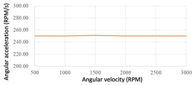
c) Motor 3
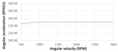
d) Motor 4
Fig. 14Demonstration of the transverse movement of the MWGV
a) Initial position
b) End position
Fig. 15Comparison of the desired and real motor angular velocities
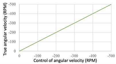
a) Motor 1
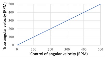
b) Motor 2
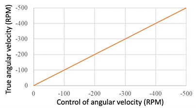
c) Motor 3
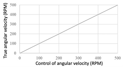
d) Motor 4
5. Conclusions
In the field of Industry 4.0 and Smart Manufacturing, linear guideways and AGVs with robot arms above them have been utilized to perform mobile manipulations in the factories. Linear guideway systems were capable for heavier items but the layout was fixed. AGV systems could be more flexible but usually designed for manipulations of weights less than 15 kg. In this paper, a high-payload Mecanum-Wheel Ground Vehicle (MWGV), that was 740 kg in weight, was designed for high-payload mobile manipulation. The proposed design could at least carry 740 kg and the safety factors of the chassis and axle were 1.66 and 6.24, respectively. Each motor produced a rated torque of 119.64 Nm and could accelerate as desired. Currently, the MWGV was successfully completed. The ongoing development of this research team includes the parallel platform above the vehicle and high-payload robot arm with static balancing.
References
-
A. Kochan, “Robotic production assistants for working alongside the human operator,” Assembly Automation, Vol. 22, No. 1, pp. 26–28, Mar. 2002, https://doi.org/10.1108/01445150210416637
-
H. Kato, “Suspension type robot whose robot body runs along traveling rail,” US Patent US8122834B2, 2012.
-
P. G. Doan, “Automated guided vehicle (AGV) system,” US Patent US8527153B2, 2013.
-
“Automated Guided Vehicles (AGV)-Robotic Automation.” Robotic Automation P/L. https://www.roboticautomation.com.au/ra_solutions/automated-guided-vehicles-agv/, 2014.
-
V. Jaiganesh, J. D. Kumar, and J. Girijadevi, “Automated guided vehicle with robotic logistics system,” Procedia Engineering, Vol. 97, pp. 2011–2021, 2014, https://doi.org/10.1016/j.proeng.2014.12.444
-
I. William A. Bastian, M. Aaron Jones, “Automated guided vehicle (AGV) with batch picking robotic arm,” US Patent US10137566B2, 2016.
-
“Move_robot.” Greentrans. http://www.greentrans-agv.com/move_robot.html, 2018.
-
“Automated Guided Vehicles and Autonomous Mobile Robots.” SESTO Robotics-AGV. https://www.sestorobotics.com/archives/automated-guided-vehicles/, 2019.
-
N. Johnson, “Robot arm and methods of use,” US Patent US10646298B2, 2020.
-
“EROWA Robot Dynamic 150L.” EROWA. https://www.erowa.com/en/products/erowa-robot-dynamic-150l-12534, 2020.
-
Z.-Y. Chen, “Design and Manufacturing of A Mecanum-Wheel Ground Vehicle,” MS Thesis, Department of Mechanical Engineering, National Taiwan University of Science and Technology, 2010.
-
Z.-Y. Chen, P.-R. Liaw, V. L. Nguyen, and P. T. Lin, “Design and manufacturing of a high-payload Mecanum-wheel ground vehicle (MWGV),” in The 23rd National Conference on Mechanism and Machine Design (CSMMT 2020), Tainan, Taiwan, 2020.
-
R. Budynas and K. Nisbett, Shigley’s Mechanical Engineering Design, 10th ed. McGraw-Hill Education, 2014.
-
H. Taheri, B. Qiao, and N. Ghaeminezhad, “Kinematic model of a four mecanum wheeled mobile robot,” International Journal of Computer Applications, Vol. 113, No. 3, pp. 6–9, Mar. 2015, https://doi.org/10.5120/19804-1586
Cited by
About this article

Part of this paper was presented in The 23rd National Conference on Mechanism and Machine Design (CSMMT 2020) [12], Tainan, Taiwan in Nov. 13, 2020. The supports from Ministry of Science and Technology (MOST), Taiwan (grant numbers MOST 108-2221-E-011-129-MY3) and Center for Cyber-Physical System Innovation, which is a Featured Areas Research Center in Higher Education Sprout Project of Ministry of Education (MOE), Taiwan (since 2018) were greatly appreciated.
