Abstract
Development of biotechnology and technologies related to small size object position and placement in working area, ensuring desired orientation and fitting during movement into prescribed positions. Paper provides an effort to classify and provide a sorted list of applications in the variety of existing robotic systems to manipulate the object of micrometric size. Extensive development of robotic systems fosters intensive request of accurate and fast drives for robots and manipulators. Paper overviews and specifies a broad spectrum of micrometric scale drives, operating under certain physical effects. These drives are analyzed according to their physical domain, movement mode, stroke or angle range, generated force, speed of movement and other essential drive parameters. The paper concludes a high potential of drives development and points direction to future their application possibilities in microrobotics.
Highlights
- Given essential classification of micrometric size drives
- Comparison of various physical domain based drives
- Energy consumption effciency analysis of micrometric scale drives
- Robotic applicable microdrives
1. Introduction
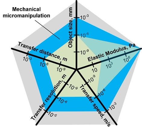
In the designing of microrobots, the knowledge, methods and materials are in principle different from macroscale robots [1]. In most cases, existing robotic technologies cannot be used in micro-scale since macroscale robots can work with separate sensors, actuators and controllers. The functions of these devices should be how-to installed in microrobot, which itself geometry is of several microns. Imaging such a small device arises quite logical thought - to create a microrobot, in which the same transducer performs sensing and moving. It can be realized soon since some microactuators have self-sensing capabilities [2]–[4]. The self-sensing actuators can be very useful in mechanical micromanipulation by creating self-sensing grippers and manipulators. The process of robotic manipulation consists of automatically controllable object observation, position, and physical transformation [5]. Mechanical micromanipulation, which is the target issue in this paper, can be performed by microrobots (performs manipulation automatically) or micromanipulators (the operator remotely controls manipulation process) that are capable of performing the motion in microscale and with micrometric accuracy [6]. The actual accuracy and quality of the micromanipulation task depend on transfer distance, particle size, mechanical properties of the particle and velocity of particle displacement (Fig. 1). The process can be called ‘micromanipulation’ if transfer distance object size fits between 1 mm and 1 µm, Elastic modulus of the object could be up to 10 MPa, the transfer speed of an object is between 1 mm/s and 1 µm/s, and transfer resolution 0.1-1 µm [6]. Therefore, the micromanipulation concept includes a scientific area between micromanipulation and nanomanipulation fields (Fig. 1).
However, micromanipulation is usually needed to transfer micrometric size objects at relatively low speed and small distances. In this case, the application area of micromanipulators becomes narrower, e.g. object size up to 100 µm, speed 1 µm/s, distance up to 1 mm. Such conditions are needed, for example, in scanning electrochemical microscopy, where the moving speed of the probe directly affects the quality of the results [7]. Various robotic micromanipulation techniques have been developed for micrometric size particle (MSP) sorting, alignment, isolation, movement, separation processes, etc. MSP manipulation with micromanipulators usually performed by a highly-skilled specialist. However, it is almost impossible to achieve high accuracy and repeatability with manually controlled devices. Therefore, precise movements are typically performed by robots.
Fig. 1A schematic representation of the micromanipulation task in respect of various parameters
For micro-sized object manipulation, different micromanipulation techniques, such as optical [8], magnetic [9], acoustic [10], electrical [11] and mechanical, can be used. Mechanical manipulation seems to be the most practical, easy controlled, and robotics involved way to manipulate small-sized objects, such as living cells or tiny particles. Also, it allows to obtain actual coordinates at a different speed and accuracy ranges on the microscale. Mechanical micromanipulation methods include physical contact and moving of micro-sized objects [12]. Such methods typically have a larger range of motion (greater than the diameter of manipulated object). They can move an object between environments, for example, liquid/air, ambience/magnetic field, or electrostatic field area [13]. Primary contact micromanipulation devices are microelectromechanical system (MEMS) microgrippers, micro hands, microrobots, micropipettes. Essential microgrippers elements, on which parameters depend accuracy, of the whole manipulation system are a pair of jaws, actuators, and motion transmitting mechanisms [14]. In microworld, the surface forces have more significant influence than the inertial forces. Here, the adhesion forces between object and gripper jaws also should be considered [15]. The microactuator performs the displacement on a micro-scale. It is known several types of microactuators, which can be divided into categories by their materials properties: piezoelectric, electrothermal, electrostatic, electromagnetic, Shape Memory Alloys (SMA) [16].
The design of mechanical micromanipulation systems requires to include mechanics, architecture, components and manufacturing, actuation and sensing, micro-electro-mechanical systems integration, and control [17]. Actuation, sensing and control on a micro-scale seem to be the most important for the microrobotics field and carry significant interest for scientists and engineers. It can hardly fit in one review article; therefore, we separated the information into three separate papers: actuators (this article), sensors, and control issues for micromanipulation tasks. The discussion about applying microactuators in robotics, working principle of actuators, their classification, and advantages/disadvantages of different types of microactuators is presented in this paper.
2. Micro positioning drives and actuators
Micromanipulation systems perform manipulation with micro/nano-objects at micrometric resolution. The characteristics of modern micromanipulation systems facilitate solutions in a wide variety of microapplications, such as micro component positioning, integrated chip manufacturing [18], cell culture positioning monitoring in biomedicine [19], high-speed microscopy [20], [21], and others. For high accuracy, modern micromanipulation systems are often designed using linear drives to avoid/reduce adverse reactions and frictional effects due to conventional mechanical drives (e.g., gears, pulleys, belts, etc.) used in the case of transmission-equipped drives to transfer mechanical force. Over the years, many direct drive solutions, such as piezoelectric [22], electrothermal [23], electromagnetic [24], electrodynamic [25], etc., have been investigated and applied in modern micromanipulation systems.
2.1. Piezoelectric actuators
Piezoelectric actuators are widely used in robotic applications since they have high bandwidth [26], high power density [27], and the ability to scale to small sizes [28], [29]. The massive availability of commercial actuators with a wide variety of output parameters, the favourable ratio between input voltage to output displacement brings notoriety and popularity between engineers and [30]. Microgrippers, based on the piezoelectric effect, are used in microinjections, DNA sequencing, ultrasonic blood clot removal, microsurgery, and more [31]. The inverse and converse piezoelectric effects can be used to actuate and sense simultaneously. Hence, it is possible to create robots with piezoelectric actuators which would provide feedback on their actual displacement or perceived force without any additional sensor [2]–[4], [32].
However, still persists the major challenge of using piezo actuators in the manipulation of nanomaterials and displacement at the nano-scale [33]. The use of piezoelectric drives involves some difficulties. First, to create sufficient force and displacement, it is required to use high-voltage drives driven by 150-300 V [26]. Most compact power sources suitable for use in microrobots, such as lithium batteries, solar cells, fuel cells and supercapacitors, produce an output voltage of less than 5 V, whereas connecting many such cells in series is generally useless. Second, only a fraction of the input electric power is converted into mechanical work by the piezoelectric material. The rest is stored in the capacitive storage, which must be recovered to maximize the system’s efficiency [34]. Third, piezoelectric materials suffer from huge nonlinearities, hysteresis and noticeable creep [30], resulting in that each given input provides an unexpected output. Such a situation requires complex algorithms or feedback systems to minimize the impact of those effects. In high-precision positioning and tracking systems, the positioning mechanisms of the piezoelectric actuators usually have controllers with closed-loop systems based on various position sensors [30].
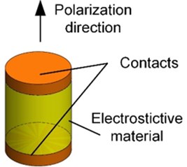
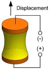
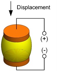
The working principle of piezoelectric actuators is based on the electrostriction effect occurring in some dielectric materials [35]. Such material deforms under the applied external electric field, which induces polarization of electric domains inside the material (Fig. 2). Deformation size depends on the object geometry and orientation, and strength of the applied electric field [31]. Piezoelectric actuators consist of a single piece or stack of piezoelectric materials, generating microscopic displacements from 10 picometres (pm) to 100 micrometres (µm) [36].
Despite mentioned challenges, the piezoelectric actuator is one type of actuators that can achieve nanometric positioning resolution and are used in various fields such as aviation [37], [38], atomic force microscopy (AFM) [39]–[41], precision machining [42], optical lens positioning systems [43] and micro-robotics [29], [44]–[46].
The actuators design and characteristics are summarized in Table 1.
Fig. 2A schematic representation of electrostriction effect: a) initial state; b) tension; c) compression
a)
b)
c)
Table 1Piezoelectric actuators reported in last 5 years
Design | Dimension, mm | Actuation voltage, V | Deflection, µm | Force, N | Year | Ref. |
Disc type | 0.2 | ±70 | 190 | – | 2015 | [47] |
Square Plate | 5.5×5.5×0.15 | 200 | 2.5-3.5 | – | 2015 | [48] |
Cantilever Type | 4×15×1 | Up to 30 | Up to 5.343 | – | 2017 | [49] |
11.3×2.5×0.1 | ±100 | +23.1/–26.7 | 2017 | [49] | ||
Self-sensing piezoelectric actuator | – | 25-200 | – | – | 2018 | [29] |
A wing with span and chord lengths of 17.8 mm and 7.4 mm | Up to 60 | – | 1.45 mN | 2018 | [50] | |
Bimorph actuator | 25-200 | 2 mN-10 N | 2019 | [44] | ||
Piezoelectric actuator | 300 | 3.83 μm | 30 N | 2019 | [51] | |
Ring-shaped, linear piezoelectric ultrasonic motor | 250 | 0.1 µm | 2.7 N | 2020 | [52] | |
∅ = 4, 0.127±70 | ±70 | 7.00-8.00 | 2020 | [53] | ||
2.2. Electrothermal actuators
Electrothermal actuators, especially soft actuators, are used in the design of mechatronic/robotic systems due to their high flexibility and adaptability: they are suitable to operate in air, vacuum, dusty media, liquid media and fits well for manipulation of biological samples [54], electronic chips [55] and other micro-objects. Soft actuators are used in microbotics because they have the possibility of large deformation, lightweight, and low power actuation [2], [56], [57]. These drives are operated at relatively low driving voltages (0.5…5 V) but can develop large forces (hundreds of mN) and displacements (up to a single mm) [56]. The main disadvantage of these drives is relatively low switching speed, limited by the heat transmission rate and heat capacitance effect, despite a wide variety of high-quality materials such as graphene, polymers, and composites [58] used in these actuators. The manufacturing of electrothermal drives is a relatively simple process combining a standard integrated circuit and MEMS manufacturing methods.
Electrothermal actuators usually operate by controlling the balance between the thermal energy generated by an electric current and heat dissipation through the environment or substrate. There are three frequent types of electrothermal drives: a) hot-and-cold-arm (also called U-shaped drive, heater, bent-beam motor, or pseudo-bimorph drive), b) chevron and c) bimorph types [58]. For operation, the hot- and cold-arm drive utilizes the asymmetrical thermal expansion of its parts. Chevron drives use full thermal expansion limited in one direction. The performance of the bimorph drive characterized by the difference in the coefficients of thermal expansion of structural materials. More information about thermal actuation techniques is provided in [59]–[62].
2.2.1. Hot-And-Cold-Arms actuators
Hot-and-cold-arm actuators are used in microgrippers, micropositioners, RF, optical systems, and micromechanical switching design [58], [63]. The principle of operation of a hot and cold arm drive is based on the asymmetric thermal deformation of a few millimetres size microstructure consisting of two or more connected beams made of a homogeneous material (Fig. 3) [64]. The difference in heating of both arms caused by the different cross-sections of the structure. A narrow (hot) beam is smaller in cross-section and is more electrical resistant, resulting in higher temperatures and higher thermal expansion than another arm. A wider (cold) beam is less resistant, and heat dissipates over a larger surface area.
Fig. 3Electrothermal U-shaped hot-and-cold-arm actuator: a) operation principle; b) temperature distribution along with the actuator profile. Adapted from [58]
![Electrothermal U-shaped hot-and-cold-arm actuator: a) operation principle; b) temperature distribution along with the actuator profile. Adapted from [58]](https://static-01.extrica.com/articles/22071/22071-img5.jpg)
a)
![Electrothermal U-shaped hot-and-cold-arm actuator: a) operation principle; b) temperature distribution along with the actuator profile. Adapted from [58]](https://static-01.extrica.com/articles/22071/22071-img6.jpg)
b)
The stroke of such drives is limited by their geometric properties, mainly by the gap size between the beams; a smaller gap allows to achieve a larger displacement [65].
2.2.2. Chevron type actuator
Chevron drives are a type of planar electrothermal drives based on the thermal expansion caused by resistive heating. This drive is usually V-shaped and is therefore also called a “V-shaped drive” or “bent beam drive” (Fig. 4) [58]. This type of drive is made of aluminium, which has a high electrical conductivity. A 1 μm layer of aluminium was deposited using the AUTO 500 evaporation and DC spray system directly on a silicon substrate. Created construction was transferred to the plate using the photolithographic mask [66]. Two sloping uniform beams are joined at the top and attached to the base at the other end. The slope of the beams facilitates movement in the plane, so the tip (or shuttler) is pushed forward.
Chevron drives have several distinct advantages over hot-and-cold arm drives, such as linear motion, no “cold” arm (correspondingly no parasitic resistive heating), and the ability to stack and cascade structures [67]. Chevron drive designs can also produce high output forces (hundreds of μN and mN) and have lower driving voltages; also, it is possible to achieve large strokes using amplification mechanisms [58]. The most apparent disadvantage of chevron drives is the external bending effect, limiting the switching temperature range. Compared to other electrothermal actuators, the chevron usually has a large footprint, narrow and long expanding beams challenging the production process due to the insufficient mask solution and stiction problems.
Fig. 4Electrothermal V-shape actuator, adapted from [59]
![Electrothermal V-shape actuator, adapted from [59]](https://static-01.extrica.com/articles/22071/22071-img7.jpg)
2.2.3. Bimorph type actuator
Bimorph actuator consists of two or more layers of different materials and uses a difference in the coefficient of thermal expansion (CTE) [68], [69]. Usually, the bimorph electrothermal drive contains one material with a high CTE and another material with a low one (Fig. 5). By heating the actuator with electric current, the Joule heat will generate more significant expansion in the layer of high CTE, and the stress caused will force the whole structure to bend from the plane towards the layer of low CTE. Often, pre-bending of the fibre occurs after release from the substrate due to the higher residual stress accumulated in the high CTE layer during the high-temperature fabrication process [59].
Fig. 5Bimorph actuator: a) initial state; b) under actuation. Adapted from [59]
![Bimorph actuator: a) initial state; b) under actuation. Adapted from [59]](https://static-01.extrica.com/articles/22071/22071-img8.jpg)
a)
![Bimorph actuator: a) initial state; b) under actuation. Adapted from [59]](https://static-01.extrica.com/articles/22071/22071-img9.jpg)
b)
![Bimorph actuator: a) initial state; b) under actuation. Adapted from [59]](https://static-01.extrica.com/articles/22071/22071-img10.jpg)
It is the oldest and well-tested actuation design of all electrothermal drives. Bimorph drives have been studied in the fields of micromanipulation, optical devices, scanning probe microscopy, and nanolithography, as well as tunable radiofrequency devices [58], [70]. The operation principle of these actuators provides a wide range of design possibilities, using different geometric configurations, the use of several layers and their thickness ratios, a large selection of materials and combinations. The main disadvantages of these drives are the heterogeneous structure, which can experience shear stresses at the interface between the layers, which can shorten the service life of bimorph type devices [58]. The summary of the reports focused on electrothermal actuators during the last 5 years provided in Table 2.
Table 2Electrothermal actuators reported in the last 5 years
Design | Material | Forces/displacements | Input power, W | Ref. |
Thermal bimorph actuator, used in microgripper | Aluminum; Silicon | 140 µm (deflection) | 80 mW | [55] |
Electrothermal actuator in soft robot | single-walled carbon nanotubes; silicone based rubber elastomers materials, PDMS | bending angle over 540° | – 12 V (driving voltage) | [68] |
Tri-layer electrothermal actuator | carbon nanotubes; Kapton polymer; aliphatic urethane acrylate monomers | – | – | [69] |
Thermal vertical bimorph actuator 1000 µm long beam 1400 µm long beam | Aluminium; Silicon | 4.5 µm 4 µm | 3 mW 1 mW | [71] |
Beam with a multimorph structure | Aluminium; Silicon oxide | 2.1 µm | – | [72] |
2.2.4. Unconventional actuators
Besides mentioned hot-and-cold arm, chevron and bimorph type actuators, there are some types of electrothermal actuators, which cannot be clearly assigned to the categories mentioned before. These would be actuators based on expanding bars [73], silicon-polymer stacked actuators [74], microspring actuators [75], actuators of combined geometry [76]. Such drives use the basic principle of thermal expansion due to resistive heating (Fig. 6).
The rapid development of MEMS technologies provides new opportunities for the miniaturization and development of various biomedical devices and bioMEMS systems. The typical applications of these microelectromechanical systems and devices are cardio devices, microneedles, chip devices for rapid chemical/biological analysis, microsurgical robots and in-vivo drug delivery systems with precise dose and timing control. MEMS actuators are widely used in this type of device to ensure their precise control. The key design elements of these devices are MEMS technology based electrothermal actuators, which have become a promising technology that plays a vital role in enabling a wide range of micromanipulation devices [77].
Fig. 6Unconventional electrothermal actuators: a) microgripper based on expanding bars; b) microgripper based on the silicon-polymer stack; c) microspring. Adapted from [58]
![Unconventional electrothermal actuators: a) microgripper based on expanding bars; b) microgripper based on the silicon-polymer stack; c) microspring. Adapted from [58]](https://static-01.extrica.com/articles/22071/22071-img11.jpg)
a)
![Unconventional electrothermal actuators: a) microgripper based on expanding bars; b) microgripper based on the silicon-polymer stack; c) microspring. Adapted from [58]](https://static-01.extrica.com/articles/22071/22071-img12.jpg)
b)
![Unconventional electrothermal actuators: a) microgripper based on expanding bars; b) microgripper based on the silicon-polymer stack; c) microspring. Adapted from [58]](https://static-01.extrica.com/articles/22071/22071-img13.jpg)
c)
2.3. Electromagnetic actuators
Electromagnetic actuators are the ones with simple driving mode, large displacements, low actuation frequencies, and planar structures [78]. The basic electromagnetic actuator consists of a flexible movable membrane, electromagnetic coil, magnetic chamber or spacer and bulk permanent magnet [79]. Several attempts to improve membrane characteristics are related to the development of composite materials based on polymers [79], [80]. Electromagnetic actuators operating principle is based on magnetic interaction force between the permanent magnet and the electromagnetic field generated in conductive material [81]. Typically electromagnetic actuators consist of a stationary coil and movable magnet placed in the coil-generated electric field [82], but the design with stationary mounted permanent magnets and movable coils is also reported [81]. The basics and principal operation of electromagnetic actuation are well described in [83].
Electromagnetic actuators are used in various devices: from industrial robotics to the automotive and biomedical industries. The main advantage of electromagnetic drives is a high magnetic force, which causes high tuning frequency. The rapid generation of an electromagnetic field causes high vibrational velocity [84]. The electromagnetic actuator can be used for precise regulation of the input power. The power consumption of electromagnetic drives ranges from 13 mW to 7 W, which is the widest range compared to other drives [85].
Usually moving part of these drives is often constructed by arranging a permanent magnet in a Halbach configuration to achieve translation and levitation. The motion forces (or Lorentz forces) are generated under a part of the moving magnet with the help of a current-carrying coil. The geometrical parameters of the permanent magnet are essential in the positioning stages. These parameters are important for positioning output characteristics such as movement distance and power [86].
There are few types of electromagnetic drives. The basic types of them presented below.
2.3.1. Levitation micro-actuators
Levitation micro-actuators (LMA) induces restoring forces applied on the target environment or compensate for a gravitational force that stably keeps the microobject in equilibrium without mechanical attachment (Fig. 7). As shown in the figure of the definition of microactuators, there are distinguished two cases of levitating microactuator, acting on the environment and acting without the target environment. LMA are widely used in the new generation of microsensors and actuators. They have higher performance possibilities to overcome the dominance of friction through inertial forces on a micro-scale [87]. Levitating microactuators can be classified as electric, inductive, magnetic, diamagnetic, superconducting, and optical, depending on the applied field [88].
Fig. 7Levitating microactuators: a) acting on the environment; b) acting without targeted environment. F – a force generated by the actuator, m – levitated microobject mass, g – acceleration of free fall. Adapted from [88]
![Levitating microactuators: a) acting on the environment; b) acting without targeted environment. F – a force generated by the actuator, m – levitated microobject mass, g – acceleration of free fall. Adapted from [88]](https://static-01.extrica.com/articles/22071/22071-img14.jpg)
a)
![Levitating microactuators: a) acting on the environment; b) acting without targeted environment. F – a force generated by the actuator, m – levitated microobject mass, g – acceleration of free fall. Adapted from [88]](https://static-01.extrica.com/articles/22071/22071-img15.jpg)
b)
2.3.2. Inductive levitation micro-actuators
The first prototype of an induction levitation micromotor (ILMA) microprocessor was developed and manufactured by Shearwood et al. [89]. ILMA microactuator is a two-coil design that incorporates an embedded stabilization and levitation coil fabricated using surface chip technology in a soft magnetic support plane (Fig. 8). This type of drive was able to stably levitate an aluminium disc with a diameter of 400 μm and a thickness of 12 μm. There were lots of ILMA modifications such as added additional coil [90], separately fabricated coils for levitation and rotation [91], instead of planar coil design chosen spiral design [92], developed 3D micro-coil design [93].
Prototype design with an integrated polymer magnetic composite core developed in 2016 has the lowest operating temperature, which reached only about 60 ℃ [94].
Fig. 8Configurations of inductive levitation microactuators: a) two coils design of inductive levitation microactuators; b) spiral coil design of inductive levitation microactuators; c) 3D micro-coil design of inductive levitation microactuators. Adapted from [88]
![Configurations of inductive levitation microactuators: a) two coils design of inductive levitation microactuators; b) spiral coil design of inductive levitation microactuators; c) 3D micro-coil design of inductive levitation microactuators. Adapted from [88]](https://static-01.extrica.com/articles/22071/22071-img16.jpg)
a)
![Configurations of inductive levitation microactuators: a) two coils design of inductive levitation microactuators; b) spiral coil design of inductive levitation microactuators; c) 3D micro-coil design of inductive levitation microactuators. Adapted from [88]](https://static-01.extrica.com/articles/22071/22071-img17.jpg)
b)
![Configurations of inductive levitation microactuators: a) two coils design of inductive levitation microactuators; b) spiral coil design of inductive levitation microactuators; c) 3D micro-coil design of inductive levitation microactuators. Adapted from [88]](https://static-01.extrica.com/articles/22071/22071-img18.jpg)
c)
2.3.3. Magnetic levitation micro-actuators
A contactless magnetic actuator has no kinematic restrictions, where forces of gravity or inertia are balanced by electromagnetic force, typically presented by levitating EM drives [88]. A magnetically levitated micro-actuator (MLMA) composed of three silicon layers and a permanent magnet was presented by Ye et al. in early 1997 [95]. The device was fabricated using micromachining technology. The top layer of silicone was composed of a groove and a plurality of small pairs of square-shaped reels for generating driving forces. The middle layer of silicone had a groove and a moving permanent magnet guide. In the lower layer was built a long rectangular reel, which was used to create levitation force. For the bistable switching principle as a microswitch in Dieppedale et al. used a 5 × 40 × 100 μm levitating mobile magnet [96]. Using a set of parallel reels, Ruffert et al. researched and fabricated a linear drive based on active levitation (Fig. 9) [97]. The application of a magnetic levitation microdrive to dual-inertia motors or micromotors was proposed in 2005 by Dauwalter and Ha [98].
Fig. 9Microactuators of magnetic levitation (I electric direct current): a) rectangular reel built on the bottom layer used to generate levitating force, b) set of reels for the linear actuator. Adapted from [88]
![Microactuators of magnetic levitation (I electric direct current): a) rectangular reel built on the bottom layer used to generate levitating force, b) set of reels for the linear actuator. Adapted from [88]](https://static-01.extrica.com/articles/22071/22071-img19.jpg)
a)
![Microactuators of magnetic levitation (I electric direct current): a) rectangular reel built on the bottom layer used to generate levitating force, b) set of reels for the linear actuator. Adapted from [88]](https://static-01.extrica.com/articles/22071/22071-img20.jpg)
b)
2.3.4. Soft electromagnetic actuators
Soft electromagnetic actuators (SEMAs) are designed by replacing solid metal coils with liquid-metal channels embedded in elastomeric shells (Fig. 10) [99]. The liquid metal reels are subjected to Lorentz forces, which are mainly generated by the radial magnetic field component. The solid connection between the permanent magnet and the reel prevents these actuators from becoming completely soft. SEMA actuate fast and are highly controllable. Possible future applications of these drives range from soft grippers to non-invasive medicine.
Fig. 10The functionality of SEMA. Flower SEMA (top view). The elastomer support is joining the five SEMAs to one flower. Adapted from [99]
![The functionality of SEMA. Flower SEMA (top view). The elastomer support is joining the five SEMAs to one flower. Adapted from [99]](https://static-01.extrica.com/articles/22071/22071-img21.jpg)
SEMA actuators are characterized by controllable compression force, but the displacement of the moving part is poorly controllable. Therefore, their implementation in the technological application is limited.
2.3.5. Polymer based electromagnetic actuators
Flexible materials, which have good mechanical properties, high elasticity and high surface strength, have made a significant breakthrough in developing MEMS devices. Polymers based actuators could be made from elastomers [100] and ion-exchange polymers [101]. Polymers were used to obtain an extensive and exact form of moving parts, such as a diaphragm or thin membrane, cantilevers, pillars, or the combination of pillars. These moving parts, made from a soft and flexible material, can vibrate continuously and be able to respond to the magnetic field and mechanical pressure. Polymers such as PMMA, perylene, polyimide, and PDMS, have been identified and tested to become suitable for actuation purposes [79]. Thielicke et al. [102] explained the practical methodology of these drives production process, depending on the requirements of the dimensions of the structure, reaction time, torque, maximum energy consumption, the technology used, and forces applied. Polymer-based drives typically consist of a magnetic field generator part – electromagnetic coil and a magnetic membrane part – flexible membrane plus attached magnet [103]–[105]. Typically, the connection of the magnetic membrane occurs due to the deformation of the moving membrane when the generated magnetic force acts on the membrane (Fig. 11(a)).
Another principle of operation, when planar electromagnetic coil solenoid mounted on or fixed to the surface of the moving membrane (Fig. 11(b)) is provided in [79], [103]. In this case, electric current is applied to the planar coil solenoid, and induction of magnetic flux from a permanent magnet interacts with magnetic flux from the solenoid. During this process, a magnetic force is generated and acts on the membrane, which ultimately causes periodic action of the membrane structure.
One of the most limiting factors is the size of the permanent magnet, which affects the overall size of the electromagnetically controlled MEMS drive. In particular, the positioning process based on electromagnetic actuation is an acceptable option when high dynamics with extended shocks (at the millimetre level) controlled by a microcontroller are required. In addition, recent developments in microfabrication technology can significantly reduce the mass and volume of permanent magnets. These changes have led researchers to create miniature designs based on a permanent magnet. Positioning task usually requires transmission and mechanisms, mechanical structure (or platform), and feedback sensors.
Fig. 11Cross-sectional view of polymer based EM actuator: a) with moving permanent magnet, b) with moving coil. Adapted from [79]
![Cross-sectional view of polymer based EM actuator: a) with moving permanent magnet, b) with moving coil. Adapted from [79]](https://static-01.extrica.com/articles/22071/22071-img22.jpg)
a)
![Cross-sectional view of polymer based EM actuator: a) with moving permanent magnet, b) with moving coil. Adapted from [79]](https://static-01.extrica.com/articles/22071/22071-img23.jpg)
b)
2.4. Electrostatic actuators
Electrostatic control is based on the principle of Coulomb force, which acts on the surface, and greatly increases with decreasing distance between a pair of counter-electrodes. Depending on the electrodes’ arrangement, these drives can be divided into a parallel plate, comb drive, vertical comb drive, and scratch-drive [106]. Electrostatic actuators can be roughly divided into linear and rotary. Several materials, including metals, semiconductor polymers, ceramics, and alloys, can be used for MEMS electrostatic actuators, depending on the application [107].
The electrostatic drive mechanism is widely used in MEMS and nanoelectromechanical systems (NEMS) due to its advantages and simplicity of the mechanism. Various electrostatic actuators have been developed and used in many areas, from relay and switches to displays and valves [107]. Electrostatically controlled MEMS devices have fast response, low power consumption, and they are compatible with standard processes for integrated circuits. Depending on the area where these drives will be used, factors such as switching voltage, operating speed, shock (displacement), switching force and stored energy are essential [109].
2.4.1. Parallel plate actuator
Parallel plate drives widely used in microsurgery, manufacturing, radio frequency signals [109]. The essence of the electrostatic action of a parallel plate is based on the charge accumulation in two electrostatically separated parallel membranes that work as a capacitor (Fig. 12) The top plate is suspended with an elastic restoring force for movement along the vertical -axis until the bottom plate remains fixed [110].
Fig. 12Operating principle of parallel plate drive
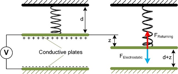
The gap d between two plates is a very important parameter that determines the magnitude of the maximum voltage that can be applied to the actuator. This type of actuator has an advantage over others since they have a low operating voltage. The parallel plate microactuator design can be adapted to systems using tightly packed micromotors [110].
2.4.2. Comb drive actuator
Comb drive actuators consist of two fingers fragmented structures (Fig. 13). One part of the comb is attached, and the other is connected to a compliant suspension. Due to the voltage difference between these structures, electrostatic forces will cause the deflection of the moving comb structure [111]. Voltage-controlled comb-drive actuators are pretty attractive in micro-positioning because of the lateral exposed electrostatic force independent of the position. Comb drive actuators can also be divided into lateral and vertical depending on the layout of the comb.
Fig. 13Comb drive actuators: a) linear, b) rotary. Adapted from [112], [113]
![Comb drive actuators: a) linear, b) rotary. Adapted from [112], [113]](https://static-01.extrica.com/articles/22071/22071-img25.jpg)
a)
![Comb drive actuators: a) linear, b) rotary. Adapted from [112], [113]](https://static-01.extrica.com/articles/22071/22071-img26.jpg)
b)
The most significant disadvantages of comb-drive actuators are the high driving voltage, the slight offset in direct current driving mode and the large layout area [114]. A vertical comb-drive actuator is used to achieve greater angular movement. However, at low voltages, the vertical comb-drive actuator cannot achieve a larger deflection angle.
Actuators of this type are used as resonators, electromechanical filters, microscrapers and also used in MEMS [115].
2.4.3. Scratch drive actuator
Scratch drive actuator (SDA) was invented by Akiyama and Shono [116]. The main part of the actuator movement is a plate with two bushings, one of them anchored (Fig. 14). The plate is pulled down towards the substrate when the voltage is applied. When the voltage is switched off, the drive returns to its original position, using a pulse voltage possible to force the SDA to move forward.
The SDA is ideal for creating motion in MEMS and especially microoptoelectromechanical systems. It produces linear motion directly, has a potentially large travel range with a relatively large force, and allows control of the position and step size to operate over a wide speed range [117].
Despite the development of energy-saving devices in various fields, MEMS electrostatic actuators still require high voltages to produce large displacements [119]. Electrostatic scratch drive actuators provide low-power, high force actuation but require power supplied by RF [120] or substrate [121] sources.
Fig. 14Scratch drive actuator, adapted from [118]
![Scratch drive actuator, adapted from [118]](https://static-01.extrica.com/articles/22071/22071-img27.jpg)
![Scratch drive actuator, adapted from [118]](https://static-01.extrica.com/articles/22071/22071-img28.jpg)
2.5. Shape memory alloy (SMA) based actuators
Shape Memory Alloy (SMA) is a smart material that can remember its original shape at low temperatures and return to a pre-deformed shape by heating. Due to these unique properties, SMA has received a lot of attention in recent years for its application in micro-drives [122]. Among SMA materials, nitinol (Ni-Ti) alloy is widely used for such drives construction, which is characterized by its high tensile strength (up to 8 %) [123].
There are various configurations of actuators based on SMA wires: flexible SMA actuators, different configurations for actuators with multiple SMA wires [124], [125]. The SMA based actuators can be used in many applications, including robotics, soft robotics, medicine, aerospace, etc. [126].
Fig. 15SMA drive, adapted from [124]
![SMA drive, adapted from [124]](https://static-01.extrica.com/articles/22071/22071-img29.jpg)
The advantages of SMA drives are high power-to-weight ratio, biocompatibility, small size, simple mechanical design and quiet operation. These advantages allow SMA drives to be adapted for various purposes, such as soft robotics [123], [127], [128] robotic surgical systems [129] and grippers [130]. Along with other control methods, the shape memory alloy (SMA) drives have been used to control many devices, including micropositioning.
The disadvantages of SMA actuators are high hysteresis error, high power consumption, and slow response time, which do not significantly affect the manipulation process of the specified task [131]. SMA drives are also non-linear, encouraging additional efforts to develop a unique mechanical design and an advanced control strategy [123].
A new model of SMA resistance characteristic was proposed based on the constitutional model of variable speed phase transformation [132]. The influence of different parameters such as thermal resistance, length, SMA cross-sectional area and temperature dependence on resistance was considered. This model will further encourage research into the management of SMA materials-based systems and facilitate the ease and miniaturization of SMA-based structures.
One of the types of SMA actuators can be the SMA spring, which works on the principle of tense muscles (Fig. 16). This kind of SMA actuator achieves a displacement of high force and rapid response [126].
Fig. 16SMA longitudinal drive, adapted from [126]
![SMA longitudinal drive, adapted from [126]](https://static-01.extrica.com/articles/22071/22071-img30.jpg)
3. Conclusions
The overview of mechanical methods of robotic micromanipulation revealed a wide area of applications and dimensional range of the drives. Manipulation of the micrometric scale objects within working area became a frequent task, but solutions for these tasks remain mosaicking about a wide variety of drives, hardware and control software. This paper focuses on drives, used for displacement on microscale. They can be divided into categories by their materials properties: piezoelectric, electrothermal, electrostatic, electromagnetic, and Shape Memory Alloys (SMA). Implementation of piezoelectric drives is well known, classical, easily accessible and adaptable solution, frequently used in microrobotics. Nevertheless, the recent progress in microtechnologies and manufacturing of small-size structures, such as MEMS technology, allows to create accurate and fast micro- and nano- drives. They have an advantage against piezoelectric drives due to their versatility and cover application range where the piezoelectric type drives are not suitable due to their own properties. For example, electrothermal actuators ensure quite stable positioning and uses low voltage power supply. Electrostatic actuators are fast, but have a position fluctuation and its operation depends on ambience dielectric constant. Electromagnetic drives are best controllable in the positioning and has low internal friction. The advantage of SMA are of the simplest design, and their features fits only for the specific applications.
The actuators, used in microrobotics for object micromanipulation are classified by physical properties and operating principles. This review creates the possibilities for future developers and users of this equipment. Following this classification, we can state that there are many actuators of a similar level of functional parameters, such as stroke, positioning accuracy, and generated force. Depending on the solutions sought, the actuators can be selected according to a required movement trajectory, power, stroke, accuracy, operational speed, linearity or stability. Some of mechanical actuators generate undesired electric/magnetic field or dissipated heat. These factors can affect the manipulation process or object, for example, to harm biological object.
Our research findings show that despite the indefinite variety of available microactuators and their control methods, there are no universal solutions suitable for every case of micromanipulation – the more straightforward design of the actuator, the more complex its control.
References
-
D.-O. Lee, L.-H. Kang, and J.-H. Han, “Active Vibration Isolation Demonstration System Using the Piezoelectric Unimorph with Mechanically Pre-stressed Substrate:,” Journal of Intelligent Material Systems and Structures, Vol. 22, No. 13, pp. 1399–1409, Sep. 2011, https://doi.org/10.1177/1045389x11411215
-
Y. Cao and J. Dong, “Self-Sensing and Control of Soft Electrothermal Actuator,” IEEE/ASME Transactions on Mechatronics, Vol. 26, No. 2, pp. 854–863, Apr. 2021, https://doi.org/10.1109/tmech.2020.3009237
-
A. Kawamata, Y. Kadota, H. Hosaka, and T. Morita, “Self-sensing piezoelectric actuator using permittivity detection,” Ferroelectrics, Vol. 368, No. 1, pp. 194–201, Oct. 2008, https://doi.org/10.1080/00150190802368495
-
T. K. Gupta, S. Kumar, A. Z. Khan, K. M. Varadarajan, and W. J. Cantwell, “Self-sensing performance of MWCNT-low density polyethylene nanocomposites,” Materials Research Express, Vol. 5, No. 1, p. 015703, Jan. 2018, https://doi.org/10.1088/2053-1591/aa9f9e
-
Z. Lu, P. C. Y. Chen, and W. Lin, “Force sensing and control in micromanipulation,” IEEE Transactions on Systems, Man and Cybernetics, Part C (Applications and Reviews), Vol. 36, No. 6, pp. 713–724, Nov. 2006, https://doi.org/10.1109/tsmcc.2006.879385
-
Z. Zhang, X. Wang, J. Liu, C. Dai, and Y. Sun, “Robotic Micromanipulation: Fundamentals and Applications,” Annual Review of Control, Robotics, and Autonomous Systems, Vol. 2, No. 1, pp. 181–203, May 2019, https://doi.org/10.1146/annurev-control-053018-023755
-
I. Morkvenaite-Vilkonciene, A. Ramanaviciene, A. Kisieliute, V. Bucinskas, and A. Ramanavicius, “Scanning electrochemical microscopy in the development of enzymatic sensors and immunosensors,” Biosensors and Bioelectronics, Vol. 141, p. 111411, Sep. 2019, https://doi.org/10.1016/j.bios.2019.111411
-
P. L. Johansen, F. Fenaroli, L. Evensen, G. Griffiths, and G. Koster, “Optical micromanipulation of nanoparticles and cells inside living zebrafish,” Nature Communications, Vol. 7, No. 1, pp. 1–8, Apr. 2016, https://doi.org/10.1038/ncomms10974
-
C. Wilhelm, F. Gazeau, and J.-C. Bacri, “Magnetic micromanipulation in the living cell,” Europhysics News, Vol. 36, No. 3, pp. 89–92, May 2005, https://doi.org/10.1051/epn:2005305
-
S. Mohanty, I. S. M. Khalil, and S. Misra, “Contactless acoustic micro/nano manipulation: a paradigm for next generation applications in life sciences,” Proceedings of the Royal Society A: Mathematical, Physical and Engineering Sciences, Vol. 476, No. 2243, p. 20200621, Nov. 2020, https://doi.org/10.1098/rspa.2020.0621
-
J. Voldman, “Electrical forces for microscale cell manipulation,” Annual Review of Biomedical Engineering, Vol. 8, No. 1, pp. 425–454, Aug. 2006, https://doi.org/10.1146/annurev.bioeng.8.061505.095739
-
M. Savia and H. N. Koivo, “Contact micromanipulation – Survey of strategies,” IEEE/ASME Transactions on Mechatronics, Vol. 14, No. 4, pp. 504–514, Aug. 2009, https://doi.org/10.1109/tmech.2008.2011986
-
H. Penny, D. T. S. Hayman, and E. Avci, “Micromanipulation system for isolating a single cryptosporidium oocyst,” Micromachines, Vol. 11, No. 1, pp. 1–16, Dec. 2019, https://doi.org/10.3390/mi11010003
-
B. R. and R. T., “Numerical simulation and experimental investigation of a topologically optimized compliant microgripper,” Sensors and Actuators A: Physical, Vol. 205, pp. 156–163, Jan. 2014, https://doi.org/10.1016/j.sna.2013.11.011
-
R. S. Fearing, “Survey of sticking effects for micro parts handling,” in 1995 IEEE/RSJ International Conference on Intelligent Robots and Systems. Human Robot Interaction and Cooperative Robots, Vol. 2, pp. 212–217, 1995, https://doi.org/10.1109/iros.1995.526162
-
M. J. Sinclair, “A high force low area MEMS thermal actuator,” in ITHERM 2000. The Seventh Intersociety Conference on Thermal and Thermomechanical Phenomena in Electronic Systems, Vol. 1, pp. 127–132, 2000, https://doi.org/10.1109/itherm.2000.866818
-
N. Belfiore, “Micromanipulation: A challenge for actuation,” Actuators, Vol. 7, No. 4, p. 85, Dec. 2018, https://doi.org/10.3390/act7040085
-
S. Xiao and Y. Li, “Visual servo feedback control of a novel large working range micro manipulation system for microassembly,” Journal of Microelectromechanical Systems, Vol. 23, No. 1, pp. 181–190, Feb. 2014, https://doi.org/10.1109/jmems.2013.2268849
-
D. Robert et al., “Magnetic micro-manipulations to probe the local physical properties of porous scaffolds and to confine stem cells,” Biomaterials, Vol. 31, No. 7, pp. 1586–1595, Mar. 2010, https://doi.org/10.1016/j.biomaterials.2009.11.014
-
T. Tuma, W. Haeberle, H. Rothuizen, J. Lygeros, A. Pantazi, and A. Sebastian, “Dual-stage nanopositioning for high-speed scanning probe microscopy,” IEEE/ASME Transactions on Mechatronics, Vol. 19, No. 3, pp. 1035–1045, Jun. 2014, https://doi.org/10.1109/tmech.2013.2266481
-
A. Dzedzickis et al., “Modification of the AFM sensor by a precisely regulated air stream to increase imaging speed and accuracy in the contact mode,” Sensors, Vol. 18, No. 8, pp. 2694–16, Aug. 2018, https://doi.org/10.3390/s18082694
-
Yangmin Li and Qingsong Xu, “Development and assessment of a novel decoupled XY parallel micropositioning platform,” IEEE/ASME Transactions on Mechatronics, Vol. 15, No. 1, pp. 125–135, Feb. 2010, https://doi.org/10.1109/tmech.2009.2019956
-
G. Vitellaro, G. L. 'Episcopo, C. Trigona, B. Ando, and S. Baglio, “A compliant MEMS device for out-of-plane displacements with thermo-electric actuation,” Journal of Microelectromechanical Systems, Vol. 23, No. 3, pp. 661–671, Jun. 2014, https://doi.org/10.1109/jmems.2013.2283520
-
J.-D. Lee, S. Khoo, and Z.-B. Wang, “DSP-based sliding-mode control for electromagnetic-levitation precise-position system,” IEEE Transactions on Industrial Informatics, Vol. 9, No. 2, pp. 817–827, May 2013, https://doi.org/10.1109/tii.2012.2219062
-
P. R. Ouyang, R. C. Tjiptoprodjo, W. J. Zhang, and G. S. Yang, “Micro-motion devices technology: The state of arts review,” The International Journal of Advanced Manufacturing Technology, Vol. 38, No. 5-6, pp. 463–478, Aug. 2008, https://doi.org/10.1007/s00170-007-1109-6
-
M. Karpelson, G.-Y. Wei, and R. J. Wood, “Driving high voltage piezoelectric actuators in microrobotic applications,” Sensors and Actuators A: Physical, Vol. 176, pp. 78–89, Apr. 2012, https://doi.org/10.1016/j.sna.2011.11.035
-
R. J. Wood, E. Steltz, and R. S. Fearing, “Optimal energy density piezoelectric bending actuators,” Sensors and Actuators A: Physical, Vol. 119, No. 2, pp. 476–488, Apr. 2005, https://doi.org/10.1016/j.sna.2004.10.024
-
N. T. Jafferis, M. Lok, N. Winey, G.-Y. Wei, and R. J. Wood, “Multilayer laminated piezoelectric bending actuators: design and manufacturing for optimum power density and efficiency,” Smart Materials and Structures, Vol. 25, No. 5, p. 055033, May 2016, https://doi.org/10.1088/0964-1726/25/5/055033
-
K. Jayaram, N. T. Jafferis, N. Doshi, B. Goldberg, and R. J. Wood, “Concomitant sensing and actuation for piezoelectric microrobots,” Smart Materials and Structures, Vol. 27, No. 6, p. 065028, Jun. 2018, https://doi.org/10.1088/1361-665x/aabdf1
-
D. V. Sabarianand, P. Karthikeyan, and T. Muthuramalingam, “A review on control strategies for compensation of hysteresis and creep on piezoelectric actuators based micro systems,” Mechanical Systems and Signal Processing, Vol. 140, p. 106634, Jun. 2020, https://doi.org/10.1016/j.ymssp.2020.106634
-
X. Gao et al., “Piezoelectric actuators and motors: materials, designs, and applications,” Advanced Materials Technologies, Vol. 5, No. 1, p. 1900716, Jan. 2020, https://doi.org/10.1002/admt.201900716
-
L. Masson, L. Xinchang, and Y. Perriard, “An optimized self-sensing piezoelectric cantilever for micro-robotic applications,” Journal of Micro-Bio Robotics, Vol. 15, No. 2, pp. 91–103, Dec. 2019, https://doi.org/10.1007/s12213-019-00120-4
-
H. Shi, W. Shi, R. Zhang, J. Zhai, J. Chu, and S. Dong, “A micromachined piezoelectric microgripper for manipulation of micro/nanomaterials,” Review of Scientific Instruments, Vol. 88, No. 6, p. 065002, Jun. 2017, https://doi.org/10.1063/1.4985110
-
T. Ozaki and N. Ohta, “Power-efficient driver circuit for piezo electric actuator with passive charge recovery,” Energies, Vol. 13, No. 11, p. 2866, Jun. 2020, https://doi.org/10.3390/en13112866
-
S. Wang, W. Rong, L. Wang, H. Xie, L. Sun, and J. K. Mills, “A survey of piezoelectric actuators with long working stroke in recent years: Classifications, principles, connections and distinctions,” Mechanical Systems and Signal Processing, Vol. 123, pp. 591–605, May 2019, https://doi.org/10.1016/j.ymssp.2019.01.033
-
H. J. M. T. S. Adriaens, W. L. de Koning, and R. Banning, “Modeling piezoelectric actuators,” IEEE/ASME Transactions on Mechatronics, Vol. 5, No. 4, pp. 331–341, 2000, https://doi.org/10.1109/3516.891044
-
M. Li, J. Yuan, Guan, and W. Chen, “Application of piezoelectric fiber composite actuator to aircraft wing for aerodynamic performance improvement,” Science China Technological Sciences, Vol. 54, No. 2, pp. 395–402, Feb. 2011, https://doi.org/10.1007/s11431-010-4212-0
-
H. Elahi, M. Eugeni, P. Gaudenzi, F. Qayyum, R. F. Swati, and H. M. Khan, “Response of piezoelectric materials on thermomechanical shocking and electrical shocking for aerospace applications,” Microsystem Technologies, Vol. 24, No. 9, pp. 3791–3798, Sep. 2018, https://doi.org/10.1007/s00542-018-3856-8
-
M. W. Fairbairn, S. O. R. Moheimani, and A. J. Fleming, “Q control of an atomic force microscope microcantilever: a sensorless approach,” Journal of Microelectromechanical Systems, Vol. 20, No. 6, pp. 1372–1381, Dec. 2011, https://doi.org/10.1109/jmems.2011.2168809
-
M. G. Ruppert, S. I. Moore, M. Zawierta, A. J. Fleming, G. Putrino, and Y. K. Yong, “Multimodal atomic force microscopy with optimized higher eigenmode sensitivity using on-chip piezoelectric actuation and sensing,” Nanotechnology, Vol. 30, No. 8, p. 085503, Feb. 2019, https://doi.org/10.1088/1361-6528/aae40b
-
I. Morkvėnaitė-Vilkončienė, A. Ramanavičienė, and A. Ramanavičius, “Atomic force microscopy as a tool for the investigation of living cells,” Medicina (Kaunas, Lithuania), Vol. 49, No. 4, pp. 155–164, 2013.
-
H. P. Syahputra, T. J. Ko, and B. M. Chung, “Development of 2-axis hybrid positioning system for precision contouring on micro-milling operation,” Journal of Mechanical Science and Technology, Vol. 28, No. 2, pp. 691–697, Feb. 2014, https://doi.org/10.1007/s12206-013-1132-5
-
Q. Li, L. Liu, X. Ma, S.-L. Chen, H. Yun, and S. Tang, “Development of multitarget acquisition, pointing, and tracking system for airborne laser communication,” IEEE Transactions on Industrial Informatics, Vol. 15, No. 3, pp. 1720–1729, Mar. 2019, https://doi.org/10.1109/tii.2018.2868143
-
S. Chopra and N. Gravish, “Piezoelectric actuators with on-board sensing for micro-robotic applications,” Smart Materials and Structures, Vol. 28, No. 11, p. 115036, Nov. 2019, https://doi.org/10.1088/1361-665x/ab43fe
-
M. Lok, E. F. Helbling, X. Zhang, R. Wood, D. Brooks, and G.-Y. Wei, “A low mass power electronics unit to drive piezoelectric actuators for flying microrobots,” IEEE Transactions on Power Electronics, Vol. 33, No. 4, pp. 3180–3191, Apr. 2018, https://doi.org/10.1109/tpel.2017.2704290
-
B.-S. Yoon, K.-H. Park, and K.-J. Yoon, “Application of piezo-composite actuator to control surface of small missile robot,” in 2007 IEEE International Conference on Robotics and biomimetics (ROBIO), pp. 1591–1595, Dec. 2007, https://doi.org/10.1109/robio.2007.4522402
-
H. K. Ma, R. H. Chen, and Y. H. Hsu, “Development of a piezoelectric-driven miniature pump for biomedical applications,” Sensors and Actuators A: Physical, Vol. 234, pp. 23–33, Oct. 2015, https://doi.org/10.1016/j.sna.2015.08.003
-
C.-H. Cheng, A.-S. Yang, C.-J. Lin, and W.-J. Huang, “Characteristic studies of a novel piezoelectric impedance micropump,” Microsystem Technologies, Vol. 23, No. 6, pp. 1709–1717, Jun. 2017, https://doi.org/10.1007/s00542-015-2769-z
-
P. Wattananukulchai and D. Isarakorn, “A comparative study based on classical and newer piezoelectric materials based unimorph actuators for Hard Disk Drive,” in TENCON 2016 – 2016 IEEE Region 10 Conference, pp. 3464–3467, Nov. 2016, https://doi.org/10.1109/tencon.2016.7848698
-
T. Ozaki and K. Hamaguchi, “Performance of direct-driven flapping-wing actuator with piezoelectric single-crystal PIN-PMN-PT,” Journal of Micromechanics and Microengineering, Vol. 28, No. 2, p. 025007, Feb. 2018, https://doi.org/10.1088/1361-6439/aaa2c8
-
L. Wang, J. Liu, S. Chen, K. Li, and Y. Liu, “Design and fabrication of a high-speed linear piezoelectric actuator with nanometer resolution using a cantilever transducer,” Smart Materials and Structures, Vol. 28, No. 5, p. 055035, May 2019, https://doi.org/10.1088/1361-665x/ab1161
-
X. Xin, X. Gao, J. Wu, Z. Li, Z. Chu, and S. Dong, “A ring-shaped, linear piezoelectric ultrasonic motor operating in E01 mode,” Applied Physics Letters, Vol. 116, No. 15, p. 152902, Apr. 2020, https://doi.org/10.1063/5.0006524
-
A. Gunda, G. Özkayar, M. Tichem, and M. K. Ghatkesar, “Proportional microvalve using a unimorph piezoelectric microactuator,” Micromachines, Vol. 11, No. 2, p. 130, Jan. 2020, https://doi.org/10.3390/mi11020130
-
N. Chronis and L. P. Lee, “Electrothermally activated SU-8 microgripper for single cell manipulation in solution,” Journal of Microelectromechanical Systems, Vol. 14, No. 4, pp. 857–863, Aug. 2005, https://doi.org/10.1109/jmems.2005.845445
-
G. Greitmann and R. A. Buser, “Tactile microgripper for automated handling of microparts,” Sensors and Actuators A: Physical, Vol. 53, No. 1-3, pp. 410–415, May 1996, https://doi.org/10.1016/0924-4247(96)80164-6
-
S. Yang and Q. Xu, “A review on actuation and sensing techniques for MEMS-based microgrippers,” Journal of Micro-Bio Robotics, Vol. 13, No. 1-4, pp. 1–14, Oct. 2017, https://doi.org/10.1007/s12213-017-0098-2
-
Y. Cao and J. Dong, “High-performance low-voltage soft electrothermal actuator with directly printed micro-heater,” Sensors and Actuators A: Physical, Vol. 297, p. 111546, Oct. 2019, https://doi.org/10.1016/j.sna.2019.111546
-
Potekhina and Wang, “Review of electrothermal actuators and applications,” Actuators, Vol. 8, No. 4, p. 69, Sep. 2019, https://doi.org/10.3390/act8040069
-
P. E. Kladitis and V. M. Bright, “Prototype microrobots for micro-positioning and micro-unmanned vehicles,” Sensors and Actuators A: Physical, Vol. 80, No. 2, pp. 132–137, Mar. 2000, https://doi.org/10.1016/s0924-4247(99)00258-7
-
A. Bonvilain and N. Chaillet, “Microfabricated thermally actuated microrobot,” in IEEE International Conference on Robotics and Automation. IEEE ICRA 2003, Vol. 3, pp. 2960–2965, 2003, https://doi.org/10.1109/robot.2003.1242045
-
Thorbjörn Ebefors, Johan Ulfstedt Mattsson, Edvard Kälvesten, and Göran Stemme, “A walking silicon micro-robot,” in Proceedings of the 10th International Conference on Solid-State Sensors and Actuators (Transducers’99}, pp. 1202–1205, Jul. 2002.
-
H. Matthew Mohebbi, L. Mason Terry, F. Karl Böhringer, T. A. Gregory Kovacs, and W. John Suh, “Omnidirectional walking microrobot realized by thermal microactuator arrays,” in ASME International Mechanical Engineering Congress and Exposition, Vol. 2, pp. 2741–2747, Feb. 2013.
-
N. B. Hubbard, M. L. Culpepper, and L. L. Howell, “Actuators for micropositioners and nanopositioners,” Applied Mechanics Reviews, Vol. 59, No. 6, pp. 324–334, Nov. 2006, https://doi.org/10.1115/1.2345371
-
R. Hickey, M. Kujath, and T. Hubbard, “Heat transfer analysis and optimization of two-beam microelectromechanical thermal actuators,” Journal of Vacuum Science and Technology A: Vacuum, Surfaces, and Films, Vol. 20, No. 3, pp. 971–974, May 2002, https://doi.org/10.1116/1.1468654
-
Q.-A. Huang and N. K. S. Lee, “Analysis and design of polysilicon thermal flexure actuator,” Journal of Micromechanics and Microengineering, Vol. 9, No. 1, pp. 64–70, Mar. 1999, https://doi.org/10.1088/0960-1317/9/1/308
-
A. Baracu et al., “Design and fabrication of a MEMS chevron-type thermal actuator,” in International Conferences and Exhibition on Nanotechnologies and Organic Electronics (Nanotexnology 2014): Proceedings of NN14 and ISFOE14, Vol. 1646, No. 1, pp. 25–30, 2015, https://doi.org/10.1063/1.4908578
-
E. T. Enikov, S. S. Kedar, and K. V. Lazarov, “Analytical model for analysis and design of V-shaped thermal microactuators,” Journal of Microelectromechanical Systems, Vol. 14, No. 4, pp. 788–798, Aug. 2005, https://doi.org/10.1109/jmems.2005.845449
-
Y.-C. Sun, B. D. Leaker, J. E. Lee, R. Nam, and H. E. Naguib, “Shape programming of polymeric based electrothermal actuator (ETA) via artificially induced stress relaxation,” Scientific Reports, Vol. 9, No. 1, pp. 1–12, Dec. 2019, https://doi.org/10.1038/s41598-019-47949-0
-
G. Tibi, E. Sachyani Keneth, M. Layani, S. Magdassi, and A. Degani, “Three-layered design of electrothermal actuators for minimal voltage operation,” Soft Robotics, Vol. 7, No. 5, pp. 649–662, Oct. 2020, https://doi.org/10.1089/soro.2018.0160
-
Y. Cao and J. Dong, “Fabrication and self-sensing control of soft electrothermal actuator,” Procedia Manufacturing, Vol. 48, pp. 43–48, 2020, https://doi.org/10.1016/j.promfg.2020.05.018
-
H. Sehr, A. G. R. Evans, A. Brunnschweiler, G. J. Ensell, and T. E. G. Niblock, “Fabrication and test of thermal vertical bimorph actuators for movement in the wafer plane,” Journal of Micromechanics and Microengineering, Vol. 11, No. 4, pp. 306–310, Jul. 2001, https://doi.org/10.1088/0960-1317/11/4/303
-
P. J. Gilgunn, Jingwei Liu, N. Sarkar, and G. K. Fedder, “CMOS-MEMS lateral electrothermal actuators,” Journal of Microelectromechanical Systems, Vol. 17, No. 1, pp. 103–114, Feb. 2008, https://doi.org/10.1109/jmems.2007.911373
-
R.-C. Voicu, M. A. Zandi, R. Müller, and C. Wang, “Nonlinear numerical analysis and experimental testing for an electrothermal SU-8 microgripper with reduced out-of-plane displacement,” Journal of Physics: Conference Series, Vol. 922, No. 1, p. 012006, Nov. 2017, https://doi.org/10.1088/1742-6596/922/1/012006
-
Trinh Chu Duc, “Electrothermal microgripper with large jaw displacement and integrated force sensors,” … Systems, Journal of, Vol. 17, No. 6, pp. 1546–1555, 2008.
-
J. K. Luo, A. J. Flewitt, S. M. Spearing, N. A. Fleck, and W. I. Milne, “Modelling of microspring thermal actuator,” in NSTI nanotechnology conference and trade show – NSTI nanotech 2004, Vol. 1, No. 1, pp. 355–358, 2004.
-
M. A. Greminger, A. S. Sezen, and B. J. Nelson, “A four degree of freedom MEMS microgripper with novel bi-directional thermal actuators,” in 2005 IEEE/RSJ International Conference on Intelligent Robots and Systems, pp. 2814–2819, 2005, https://doi.org/10.1109/iros.2005.1545137
-
D. L. Peterson, J. M. Gleisner, and R. L. Blakley, “Bovine liver dihydrofolate reductase: purification and properties of the enzyme,” Biochemistry, Vol. 14, No. 24, pp. 5261–5267, Dec. 1975, https://doi.org/10.1021/bi00695a005
-
C.-Y. Lee, Z.-H. Chen, H.-T. Chang, C.-Y. Wen, and C.-H. Cheng, “Design and fabrication of novel micro electromagnetic actuator,” Microsystem Technologies, Vol. 15, No. 8, pp. 1171–1177, Aug. 2009, https://doi.org/10.1007/s00542-008-0734-9
-
J. Yunas et al., “Polymer-Based MEMS electromagnetic actuator for biomedical application: A review,” Polymers, Vol. 12, No. 5, p. 1184, May 2020, https://doi.org/10.3390/polym12051184
-
M. M. Said, J. Yunas, R. E. Pawinanto, B. Y. Majlis, and B. Bais, “PDMS based electromagnetic actuator membrane with embedded magnetic particles in polymer composite,” Sensors and Actuators A: Physical, Vol. 245, pp. 85–96, Jul. 2016, https://doi.org/10.1016/j.sna.2016.05.007
-
A. S. Algamili et al., “A Review of Actuation and Sensing Mechanisms in MEMS-Based Sensor Devices,” Nanoscale Research Letters, Vol. 16, No. 1, pp. 1–21, Dec. 2021, https://doi.org/10.1186/s11671-021-03481-7
-
F. A. Mohd Ghazali, M. N. Hasan, T. Rehman, M. Nafea, M. S. Mohamed Ali, and K. Takahata, “MEMS actuators for biomedical applications: A review,” Journal of Micromechanics and Microengineering, Vol. 30, No. 7, p. 073001, Jul. 2020, https://doi.org/10.1088/1361-6439/ab8832
-
D. Li, F. Niu, J. Li, X. Li, and D. Sun, “Gradient-enhanced electromagnetic actuation system with a new core shape design for microrobot manipulation,” IEEE Transactions on Industrial Electronics, Vol. 67, No. 6, pp. 4700–4710, Jun. 2020, https://doi.org/10.1109/tie.2019.2928283
-
N. A. Hamid, B. Y. Majlis, J. Yunas, A. R. Syafeeza, Y. C. Wong, and M. Ibrahim, “A stack bonded thermo-pneumatic micro-pump utilizing polyimide based actuator membrane for biomedical applications,” Microsystem Technologies, Vol. 23, No. 9, pp. 4037–4043, Sep. 2017, https://doi.org/10.1007/s00542-016-2951-y
-
F. Amirouche, Y. Zhou, and T. Johnson, “Current micropump technologies and their biomedical applications,” Microsystem Technologies, Vol. 15, No. 5, pp. 647–666, May 2009, https://doi.org/10.1007/s00542-009-0804-7
-
J. S. Agashe and D. P. Arnold, “A study of scaling and geometry effects on the forces between cuboidal and cylindrical magnets using analytical force solutions,” Journal of Physics D: Applied Physics, Vol. 41, No. 10, p. 105001, May 2008, https://doi.org/10.1088/0022-3727/41/10/105001
-
K. V. Poletkin, “Static pull-in behavior of hybrid levitation micro-actuators: simulation, modelling and experimental study,” IEEE/ASME Transactions on Mechatronics, Vol. 26, No. 2, pp. 753–764, Apr. 2021, https://doi.org/10.1109/tmech.2020.2999516
-
K. Poletkin, A. Asadollahbaik, R. Kampmann, and J. Korvink, “Levitating micro-actuators: a review,” Actuators, Vol. 7, No. 2, p. 17, Apr. 2018, https://doi.org/10.3390/act7020017
-
C. Shearwood, A. D. Mattingley, M. R. J. Gibbs, R. B. Yates, P. H. Mellor, and C. B. Williams, “Levitation of a micromachined rotor for application in a rotating gyroscope,” Electronics Letters, Vol. 31, No. 21, pp. 1845–1846, Oct. 1995, https://doi.org/10.1049/el:19951232
-
C. Shearwood, C. B. Williams, R. B. Yates, P. H. Mellor, and J. Woodhead, “Electro-magnetically levitated micro-discs,” in IEE Colloquium on Microengineering Applications in Optoelectronics, 1996, https://doi.org/10.1049/ic:19960241
-
W. Zhang et al., “The study of an electromagnetic levitating micromotor for application in a rotating gyroscope,” Sensors and Actuators A: Physical, Vol. 132, No. 2, pp. 651–657, Nov. 2006, https://doi.org/10.1016/j.sna.2006.03.002
-
N.-C. Tsai, W.-M. Huang, and C.-W. Chiang, “Magnetic actuator design for single-axis micro-gyroscopes,” Microsystem Technologies, Vol. 15, No. 4, pp. 493–503, Apr. 2009, https://doi.org/10.1007/s00542-008-0769-y
-
K. Kratt, V. Badilita, T. Burger, J. G. Korvink, and U. Wallrabe, “A fully MEMS-compatible process for 3D high aspect ratio micro coils obtained with an automatic wire bonder,” Journal of Micromechanics and Microengineering, Vol. 20, No. 1, p. 015021, Jan. 2010, https://doi.org/10.1088/0960-1317/20/1/015021
-
K. V. Poletkin et al., “Polymer magnetic composite core boosts performance of three-dimensional micromachined inductive contactless suspension,” IEEE Magnetics Letters, Vol. 7, pp. 1–3, 2016, https://doi.org/10.1109/lmag.2016.2612181
-
X. Y. Ye, Y. Huang, Z. Y. Zhou, Q. C. Li, and Q. L. Gong, “A magnetic levitation actuator for micro-assembly,” in International Solid State Sensors and Actuators Conference (Transducers '97), Vol. 2, pp. 797–799, 1997, https://doi.org/10.1109/sensor.1997.635220
-
C. Dieppedale, B. Desloges, H. Rostaing, J. Delamare, O. Cugat, and J. Meunier-Carus, “Magnetic bistable micro-actuator with integrated permanent magnets,” in IEEE Sensors, 2004., Vol. 1, pp. 493–496, Apr. 2011, https://doi.org/10.1109/icsens.2004.1426208
-
C. Ruffert, R. Gehrking, B. Ponick, and H. H. Gatzen, “Magnetic levitation assisted guide for a linear micro-actuator,” IEEE Transactions on Magnetics, Vol. 42, No. 11, pp. 3785–3787, Nov. 2006, https://doi.org/10.1109/tmag.2006.879160
-
C. R. Dauwalter and J. C. Ha, “Magnetically suspended MEMS spinning wheel gyro,” IEEE Aerospace and Electronic Systems Magazine, Vol. 20, No. 2, pp. 21–26, Feb. 2005, https://doi.org/10.1109/maes.2005.1397145
-
G. Mao et al., “Soft electromagnetic actuators,” Science Advances, Vol. 6, No. 26, p. eabc0251, Jun. 2020, https://doi.org/10.1126/sciadv.abc0251
-
H. R. Choi et al., “Microrobot actuated by soft actuators based on dielectric elastomer,” in IROS 2002: IEEE/RSJ International Conference on Intelligent Robots and Systems, Vol. 2, pp. 1730–1735, Feb. 2002, https://doi.org/10.1109/irds.2002.1044005
-
Jaewook Ryu, Younkoo Jeong, Younghun Tak, Byungmok Kim, Byungkyu Kim, and J.-O. Park, “A ciliary motion based 8-legged walking micro robot using cast IPMC actuators,” in MHS2002. of 2002 International Symposium on Micromechatronics and Human Science, pp. 85–91, 2002, https://doi.org/10.1109/mhs.2002.1058016
-
E. Thielicke and E. Obermeier, “Microactuators and their technologies,” Mechatronics, Vol. 10, No. 4-5, pp. 431–455, Jun. 2000, https://doi.org/10.1016/s0957-4158(99)00063-x
-
Roer Eka, “Design consideration of planar embedded micro-coils for electromagnetic actuator of fluids injection system,” Middle-East Journal of Scientific Research, Vol. 19, No. 4, pp. 538–543, 2014.
-
R. E. Pawinanto, J. Yunas, B. Majlis, and A. Hamzah, “Design and fabrication of compact MEMS electromagnetic micro-actuator with planar micro-coil based on PCB,” TELKOMNIKA (Telecommunication Computing Electronics and Control), Vol. 14, No. 3, pp. 856–866, Sep. 2016, https://doi.org/10.12928/telkomnika.v14i3.3998
-
N.-T. Nguyen and T.-Q. Truong, “A fully polymeric micropump with piezoelectric actuator,” Sensors and Actuators B: Chemical, Vol. 97, No. 1, pp. 137–143, Jan. 2004, https://doi.org/10.1016/s0925-4005(03)00521-5
-
H. Toshiyoshi, “Electrostatic actuation,” in Comprehensive Microsystems, Elsevier, 2008, pp. 1–38, https://doi.org/10.1016/b978-044452190-3.00057-4
-
M. Yazdani and A. F. Payam, “A comparative study on material selection of microelectromechanical systems electrostatic actuators using Ashby, VIKOR and TOPSIS,” Materials and Design (1980-2015), Vol. 65, pp. 328–334, Jan. 2015, https://doi.org/10.1016/j.matdes.2014.09.004
-
V. T. Srikar and S. M. Spearing, “Materials selection for microfabricated electrostatic actuators,” Sensors and Actuators A: Physical, Vol. 102, No. 3, pp. 279–285, Jan. 2003, https://doi.org/10.1016/s0924-4247(02)00393-x
-
S. P. Burugupally and W. R. Perera, “Dynamics of a parallel-plate electrostatic actuator in viscous dielectric media,” Sensors and Actuators A: Physical, Vol. 295, pp. 366–373, Aug. 2019, https://doi.org/10.1016/j.sna.2019.06.005
-
D. Admassu, T. Durowade, S. Velicu, S. Sivananthan, and W. Gao, “Estimation of the mechanical stiffness constant of MEMS-based parallel-plate micro-actuators,” Microsystem Technologies, Vol. 27, No. 7, pp. 2751–2759, Jul. 2021, https://doi.org/10.1007/s00542-020-05022-1
-
R. Legtenberg, A. W. Groeneveld, and M. Elwenspoek, “Comb-drive actuators for large displacements,” Journal of Micromechanics and Microengineering, Vol. 6, No. 3, pp. 320–329, 1996.
-
Y. Eltagoury, M. Soliman, Y. Sabry, M. Alotaibi, and D. Khalil, “Electrostatic comb-drive actuator with high in-plane translational velocity,” Micromachines, Vol. 7, No. 10, p. 188, Oct. 2016, https://doi.org/10.3390/mi7100188
-
A. Veroli et al., “An approach to the extreme miniaturization of rotary comb drives,” Actuators, Vol. 7, No. 4, p. 70, Oct. 2018, https://doi.org/10.3390/act7040070
-
J. C. Chiou and Y. J. Lin, “A novel large displacement electrostatic actuator: Pre-stress comb-drive actuator,” Journal of Micromechanics and Microengineering, Vol. 15, No. 9, pp. 1641–1648, Sep. 2005, https://doi.org/10.1088/0960-1317/15/9/005
-
G. Zhou and P. Dowd, “Tilted folded-beam suspension for extending the stable travel range of comb-drive actuators,” Journal of Micromechanics and Microengineering, Vol. 13, No. 2, pp. 178–183, Mar. 2003, https://doi.org/10.1088/0960-1317/13/2/303
-
T. Akiyama and K. Shono, “Controlled stepwise motion in polysilicon microstructures,” Journal of Microelectromechanical Systems, Vol. 2, No. 3, pp. 106–110, 1993, https://doi.org/10.1109/84.260254
-
L. Li, J. G. Brown, and D. Uttamchandani, “Study of scratch drive actuator force characteristics,” Journal of Micromechanics and Microengineering, Vol. 12, No. 6, pp. 736–741, Nov. 2002, https://doi.org/10.1088/0960-1317/12/6/303
-
E. Sarajlic, C. Yamahata, E. Berenschot, N. Tas, H. Fujita, and G. Krijnen, “High-performance shuffle motor fabricated by vertical trench isolation technology,” Micromachines, Vol. 1, No. 2, pp. 48–67, Jul. 2010, https://doi.org/10.3390/mi1020048
-
C. Sano, M. Ataka, G. Hashiguchi, and H. Toshiyoshi, “An electret-augmented low-voltage MEMS electrostatic out-of-plane actuator for acoustic transducer applications,” Micromachines, Vol. 11, No. 3, p. 267, Mar. 2020, https://doi.org/10.3390/mi11030267
-
P. Basset, A. Kaiser, P. Bigotte, D. Collard, and L. Buchaillot, “A large stepwise motion electrostatic actuator for a wireless microrobot,” in Technical Digest. MEMS 2002 IEEE International Conference. Fifteenth IEEE International Conference on Micro Electro Mechanical Systems, pp. 606–609, 2002, https://doi.org/10.1109/memsys.2002.984344
-
B. R. Donald, C. G. Levey, C. D. Mcgray, I. Paprotny, and D. Rus, “An untethered, electrostatic, globally controllable MEMS micro-robot,” Journal of Microelectromechanical Systems, Vol. 15, No. 1, pp. 1–15, Feb. 2006, https://doi.org/10.1109/jmems.2005.863697
-
A. Nespoli, S. Besseghini, S. Pittaccio, E. Villa, and S. Viscuso, “The high potential of shape memory alloys in developing miniature mechanical devices: A review on shape memory alloy mini-actuators,” Sensors and Actuators A: Physical, Vol. 158, No. 1, pp. 149–160, Mar. 2010, https://doi.org/10.1016/j.sna.2009.12.020
-
Z. Guo, Y. Pan, L. B. Wee, and H. Yu, “Design and control of a novel compliant differential shape memory alloy actuator,” Sensors and Actuators A: Physical, Vol. 225, pp. 71–80, Apr. 2015, https://doi.org/10.1016/j.sna.2015.01.016
-
D. Copaci, D. Blanco, and L. E. Moreno, “Flexible shape-memory alloy-based actuator: mechanical design optimization according to application,” Actuators, Vol. 8, No. 3, p. 63, Aug. 2019, https://doi.org/10.3390/act8030063
-
A. Villoslada, A. Flores, D. Copaci, D. Blanco, and L. Moreno, “High-displacement flexible Shape Memory Alloy actuator for soft wearable robots,” Robotics and Autonomous Systems, Vol. 73, pp. 91–101, Nov. 2015, https://doi.org/10.1016/j.robot.2014.09.026
-
J. Jeong, I. B. Yasir, J. Han, C. H. Park, S.-K. Bok, and K.-U. Kyung, “Design of shape memory alloy-based soft wearable robot for assisting wrist motion,” Applied Sciences, Vol. 9, No. 19, p. 4025, Sep. 2019, https://doi.org/10.3390/app9194025
-
S. Kim, E. Hawkes, K. Choy, M. Joldaz, J. Foleyz, and R. Wood, “Micro artificial muscle fiber using NiTi spring for soft robotics,” in 2009 IEEE/RSJ International Conference on Intelligent Robots and Systems (IROS 2009), pp. 2228–2234, Oct. 2009, https://doi.org/10.1109/iros.2009.5354178
-
Young Pyo Lee, Byungkyu Kim, Moon Gu Lee, and J.-O. Park, “Locomotive mechanism design and fabrication of biomimetic micro robot using shape memory alloy,” in IEEE International Conference on Robotics and Automation, 2004. Proceedings. ICRA '04. 2004, Vol. 2004, No. 5, pp. 5007–5012, 2004, https://doi.org/10.1109/robot.2004.1302511
-
R. J. Webster and B. A. Jones, “Design and kinematic modeling of constant curvature continuum robots: a review” The International Journal of Robotics Research, Vol. 29, No. 13, pp. 1661–1683, Nov. 2010, https://doi.org/10.1177/0278364910368147
-
Shaoze Yan, Xiajie Liu, Feng Xu, and Jinhui Wang, “A gripper actuated by a pair of differential SMA springs” Journal of Intelligent Material Systems and Structures, Vol. 18, No. 5, pp. 459–466, May 2007, https://doi.org/10.1177/1045389x06067110
-
H. Llewellyn-Evans, C. A. Griffiths, and A. A. Fahmy, “Design process and simulation testing of a shape memory alloy actuated robotic microgripper,” Microsystem Technologies, Vol. 26, No. 3, pp. 885–900, Mar. 2020, https://doi.org/10.1007/s00542-019-04599-6
-
Y. Lu, R. Zhang, Y. Xu, L. Wang, and H. Yue, “Resistance characteristics of sma actuator based on the variable speed phase transformation constitutive model,” Materials, Vol. 13, No. 6, p. 1479, Mar. 2020, https://doi.org/10.3390/ma13061479
Cited by
About this article

This project has received financial support from the Research Council of Lithuania (LMTLT), No. P-LLT-21-6, State Education Development Agency of Latvia, Ministry of Science and Technology (MOST) of Taiwan.
