Abstract
Recent progress in the field of microrobotics tightly linked to an ability to grab an object firmly without the damage to the surface and structure. Process of biological object grabbing by microgrippers faces numerous limitations in the mechanical, electric and thermal domains; these limitations varies from case to case with different objects, therefore, analysis in this area was an aim of this review. This paper covers an area of micrometric size biological object manipulation and performs an analysis of used actuators and kinematic chains of the grippers in the sense of their application. Limitations and restriction of microgrippers applications analysed along available publications in numerous recent references as well as their successful implementation history. Paper provides result of analysis as compact big picture, which will be useful for researchers and designers in the area of microrobotics.
1. Introduction
Robotic manipulation of living cells finds broad applications in the biotechnology, medicine and pharmaceutic industry. Intensively developing micrometric size robotic technologies are often limited by a lack of proper operation tools, such as microgrippers. They can perform gripping, orientation and transportation of living cells using mechanical, electrostatic or vacuum technologies. Microgrippers brings multiply limitations and restrictions to the microrobot operation. The biocompatibility of the micro-grippers materials is one of the very important features in their practical applications. The initial state of the microgrippers, which can be defined as normally closed [1] or normally open [2], also plays a significant role in the whole manipulation process. The second group of grippers requires extra control actions to keep grabbing force in the required range, but this allows dealing with pressure-sensitive objects. According to their design, microgrippers are possible to classify into two types, namely cantilever and flexible hinge. The choice of the design depends on the shape and size of the grasped object. In this review, we focus on the micromanipulation of living cells with mechanical grippers. These devices consist of a pair of gripping jaws, a kinematic amplifier and a drive mechanism that uses different actuator types.
Moving and fixing the microgripper jaws for object grabbing are main its’ functions. The implemented drive or actuator mainly influences the design of the gripper. Furthermore, the most typical and practical gripper classification methods are based on various physical effects used in the microgripper drives and actuators. The most used drives are electrostatic, thermal (Shape Memory Alloy (SMA) and electrothermal), electromagnetic, piezoelectric. As less frequent implementations, ultrasonic, acoustic, laser molecular pneumatic, hydraulic, optical, fluorescent, resonant energy transfer, acoustic, electrophoretic, and freezer technologies could be mentioned [3].
Microelectromechanical (MEMS) grippers (mechanism and actuator produced in a single chip) are popular tools for manipulating objects of micrometric size. MEMS microgrippers can pick up, transport, orientate and place a particle in their medium. It can contain integrated force sensors on the chip to quantify and control the gripping force, avoid particle damage, and even determine its mechanical properties by manipulation. MEMS devices are characterised by low weight, high resolution, stable operation, easy integration with other devices and low power consumption. MEMS micro-grippers for particle manipulation covers the following types: electrostatic micro-grippers, electrothermal micro-grippers, electromagnetic micro-grippers, shape memory alloy (SMA) micro-grippers and piezoelectric microgrippers. They can embrace some gripper types, but there are many items that are not suitable for MEMS technology.
The advanced design of the grippers includes jaw position and grabbing force control, not all actuator technologies suits for feedback control. Operating with biological material faces specific conditions. Multiverse biological material properties require a particular approach to the process and equipment of grabbing and holding them in the aqueous environment.
This review focuses on the microgrippers for manipulating living cells and other biological micrometric scale objects and provides a detailed analysis of their achievable characteristics and possible implementation according to the actuator type.
2. Electrostatic microgrippers
Electrostatically actuated microgrippers operate by applying a high voltage to the jaw opening/closing actuator, that pull or push arms one in relation to the other using Coulomb forces [4]. The properties of implemented actuators highly influence the general design of microgrippers and the efficiency of their operating (Table 1). Depending on the type of electrostatic actuator structure, they can be defined as lateral comb and transverse drives that generate linear or rotary movement. This kinematic feature defines gripper design. The rotary actuator allows avoiding the use of high voltage in the electrical system. For example, the voltage of 100 V can develop up to 94 µm of jaw displacement [5]. The structure of such grippers’ actuators consists of two interconnected combs, which pulls or repels due to the applied voltage, opening or closing set of jaws.
Table 1Electrostatic microgrippers
Design | Actuation voltage Max force | Displacement | Object size | Ref. |
Silicon-processed overhanging microgripper | Up to 50 V 102.7 nN | – | – | [9] |
Microgripper with thermal bimorph actuator | – 250 µN | 140 µm | – | [11] |
Monolithic electrostatic micro-gripper with an integrated force sensor | 150 V 380 µN | 100 µm | 20-90 µm | [12] |
MEMS microgripper with integrated force sensor | 85 V 384 µN | 15 µm | 30 µm | [13] |
Dual axis electrostatic MEMS microgripper | 120 V 190 µN | 70 µm (-axis) 18 µm (-axis) | Up to 190 µm | [10] |
Micro gripper with self-locking mechanism | 33 V – | 100 µm | 40.6 µm | [14] |
Electrostatic comb-based microgripper FEM modelling | 100 V | 32.5 µm | Up to 84 µm | [16] |
MEMS microgripper with rotatory electrostatic comb-drive actuators | 23.4 VDC 129.2 VAC | 95.5 μm | 40 µm | [18] |
Nonlinear electrostatic microgripper with piezoelectric force sensor | 110 V – | 30 µm | 1 µm-30 µm | [6] |
Electrostatic microgrippers are characterised by low energy consumption, high-frequency response, and very low hysteresis. The main limitation in applying these devices is the relatively high driving voltage, which becomes dangerous for living cells and makes technically difficult to operate in the aqueous environment.
Despite mentioned issues, this technology has existed long ago but was limited by available precise machining technologies. The present growth of modern manufacturing and control technologies and resulted in a series of electrostatic devices. Commercially available microgripper FT-G 100 is suitable for the wide applications area, from high-precision pick-and-place operations to single-cell sorting (Fig. 1(a)) [6]. This gripper provides gripper jaws opening distances of 30 μm, 60 μm and 100 μm (respectively customisable up to 400 μm) with controllable nanometre distance resolution. This gripper is initially open; therefore, the full closure of the jaws occurs with the maximum actuation voltage. Force feedback increases the efficiency and reliability of automated microcontroller systems and assembly processes [6]. On the FT-G 100 microgripper base, a model of a nonlinear electrostatic device with an integrated force sensor is proposed for object manipulation in the micrometric world [7], [8]. For the reliable control of gripping force, authors designed a force feedback controller based on the Kalman filter. A Kalman filter evaluates the noise states to overcome the limitations caused by the low signal to noise ratio. Kalman filtration allowed increasing the resolution of the gripping force, which was limited by the noise level and evaluated to design LQG (linear square Gaussian) optimal gripping force control.
Electrostatic microgrippers based on MEMS technology were introduced in 1992 [9]. Using MEMS fabrication technology, it is possible to manufacture electrostatic microgrippers with a simple design and integrated capacitive [10] or piezoresistive sensors [11] for sensing jaws position and gripping force. For example, in [11] presented MEMS gripper with thermal bimorph actuator and piezoresistive sensor, ensuring a sensitivity of 33 mV/mN·V. Felix Beyeler et al. designed a monolithic micro-gripper with an integrated force sensor capable of manipulating suspended HeLa cancer cells with a diameter of approximately 20 µm [12]. This micro-gripper provides real-time force feedback and has high sensitivity. The experiment proved that cells survive during manipulation. In addition, the capacitive sensor in the microgripper can be used as an actuator when force sensing is not required [13].
Fig. 1Electrostatic microgrippers. a) the FT-G 100 Microgripper [6], b) gripper with self-locking mechanism [14]
![Electrostatic microgrippers. a) the FT-G 100 Microgripper [6], b) gripper with self-locking mechanism [14]](https://static-01.extrica.com/articles/22324/22324-img1.jpg)
a)
![Electrostatic microgrippers. a) the FT-G 100 Microgripper [6], b) gripper with self-locking mechanism [14]](https://static-01.extrica.com/articles/22324/22324-img2.jpg)
b)
The main drawbacks of MEMS microgrippers are complex architectures, nonlinear behaviour, and parameters uncertainties. Therefore they require accurate modelling and extensive Finite element analysis before manufacturing [5], [15]-[17].
Despite a well-established design in the field of microgrippers’ kinematics, there is still room for new solutions and mechanisms. Yuan et al. developed a new mechanism (Fig. 1(b)) that allows the gripper to self-lock during operation [14]. In this way, the object kept in the jaws fixed for a long time without applying voltage. This reduces the possible damage to the grabbed object and diminishes the danger of accidental voltage leak from jaws. Designed an electrostatically controlled micro-gripper capable of manipulating micro-objects in the range 0…100 µm at the operating voltage 0…33 V, respectively.
Ein Gaafar et al. presented an electrostatic comb-based microgripper suitable for microsurgery, micro-component assembly, measurement of living cell properties and small-scale biological tissue manipulation. The authors designed a low-temperature drive microgripper developing a low-stress level of grabbing surface [16]. The design of this gripper was tested on two-element kits, silicon and silicon oxide and polysilicon and silicon nitride. During the experimental research, silicon and silicon oxide provided better results because the gripper jaws can move to a larger range (from 20 to 84 μm).
Electrostatic microgrippers have many advantages, such as high positioning resolution, fast response, low power consumption and good compatibility with silicon microprocessors. To manipulate cells, the jaws of the electrostatic microgripper do not increase their temperature during operation and, when properly configured, may have zero electrical potential to the manipulating object. Due to these properties, it is particularly suitable for interacting with living cells. Disadvantages of electrostatic microgrippers are long arms, low gripping force, low energy density, limited range of tip displacement. It is essential to know that sensors and actuators for electrostatic microgrippers are generally incapable of operating in aqueous solutions. Therefore, gripper arms must be long enough to immerse them in the solution while keeping the micro-actuator and force sensor outside. However, long gripper arms reduce the grabbing force and perform apparent parasitic off-plane movements of the gripping jaws [19].
3. Thermal microgrippers
3.1. Electrothermal microgrippers
Microgrippers with integrated electrothermal actuators based on the thermal expansion of materials at low excitation voltages can generate large displacements [20]. It also has a small dimension, high operating temperatures limit use with more sensitive objects (Table 2). The first attempt of force-controlled grasping of biological cells at the nanonewton force level is demonstrated in [21]. Further development in this field resulted with a huge variety of grippers designs based on electrothermal actuation, that suits for the biological objects.
3.2. Shape memory alloy microgrippers
Shape memory alloy (SMA) actuators are widely used in micro-grippers due to their advantages, such as high power-to-weight ratio, quiet operation, low driving voltage and low cost compared to other materials [22]. The main disadvantages are smaller deformation, limited heating and cooling capacity, low energy efficiency. The MEMS gripper for manipulating and assembling micro-objects that uses a Ni-Ti SMA spring together with a Si spring was proposed by Munasinghe et al. [23]. The two jaws are secured with four Ni-Ti films that are attached to the frame. SMA and Si springs can remember and return to the position of the two tips. The SMA switch generates the heat, and the designed control circuit generates the sensor feedback. The experiment results showed that Ti-Ni could be used as an efficient way of operating the gripper. The natural frequency seems very high, thus reducing the failures due to resonance. SMA microgripper stands out with high grip force, faster grip and higher accuracy. A grip range of 120 μm, with a total gripper dimension of 2730 μm × 1500 μm × 50 μm is achieved. The schematic diagram of the SMA microgripper is shown in Fig. 2.
J. H. Kyung et al. proposed a microgripper structure with a flexible hinge for handling microparticles [25]. This microgripper consists of gripping jaws, SMA wires, two flexible hinges, a stainless housing, and a deflection meter. Flexible hinges are the area of different thicknesses from the rest of the arms, allowing realising the jaws’ maximum adhesion force. When the two SMA actuators are turned on, they begin to shrink due to the temperature change. When the electric heating current in both SMA wires is switched off, the wires cool down and expand to their original size, and the elastic restoring force of the flexible hinge opens the gripping jaw. When opening and closing jaws of the microgripper grip the micro-object, the stresses are concentrated in a thinner hinge, and most of the gripping force transferred to it. The adhesion force can be measured with a strain gauge attached to a thinner hinge [25].
Table 2Electrothermal microgrippers
Design | Object Size of object | Actuation voltage Gripping force | Displacement | Ref. |
Monolithic V-beam MEMS-based microgripper with integrated force feedback | Porcine interstitial cells Ø10-20 µm | 5 V (opening) 3.5 V (grasping) 100 nN | 57 µm 32 µm | [21] |
Microgripper based on a ‘hot and cold arm’ actuator | Human red blood cells ~Ø8 µm | 3 V – | 9 µm 5-9 µm | [27] |
Microgripper from stress-free polymer (SU8)/metal (Au) structures | Single cells | 1.94 V | Up to 262 µm 2-150 µm | [28] |
V beam electrothermal actuator | Biological cells | 5 V (opening) 1.5 V (grasping) 19.9 nN (resolution) | 65 µm 20-40 µm | [20] |
V-beam electrothermal MEMS based microgripper | Biological cells | 0-10 V 5 V (opening) 1.5 V (grasping) | – 6-72 µm | [29] |
Polymer MEMS-based microgripper | HeLa cell Ø10 µm | 1-2 V 1.2 V (grasping) | – 10 µm | [30] |
U-Beam electrothermal MEMS microgripper | Human red blood cells | 10-12 V | – 25 µm | [31] |
Polymer chopstick gripper | Viable cells 15-50 µm | 2 V | >20 µm-80 µm Ø15-50 µm | [32] |
Polymer micro robotic gripper | Danio rerio focilles 800 µm | 5 V | ~Ø500 µm | [33] |
Microgripper with embedded Au thin-film heaters | Variety of micro objects | 0.4 V | 180 μm 150 μm | [34] |
FEM based thermo structural simulations | Biological tissues and cells | 0.65 V | 50.5 µm | [35] |
SU-8 microgripper | Single cells, biological species | 1-2 V | Ø10 µm | [19] |
Bidirectional microgripper | Mice oocytes 100 µm | 300 µN ≤ 2 V | Ø100 µm | [19] |
DLC film drive microgripper | Micro objects | Micro cages can be opened at 20 mV, frequency 100 Hz | 20-100 µm | [26] |
Electrothermally actuated cell microgripper | Biological cells | 45 V (cell of 33-37 µm diameter can be enclosed) | 40-50 µm | [36] |
SU-8 microgripper | Biological cells 10 µm | 1-2 V (low voltages) | 3 µm | [19] |
Polymeric microgripper for cell manipulation | SU8 cylinders Ø100 µm | 1.94 V | 262 µm | [28] |
Fu et al. proposed the design of a smart micro-gripper made of a combination of highly compressible diamond-like carbon (DLC) and galvanised Ni bimorph structures or thin films of SU8 polymer layer. The experimental results showed that by changing the ratio of DLC film stress to DLC thickness, the curvature radius of the bimorph layer and the angular deflection can be adjusted by changing the finger’s length. This gripper can be used to capture and close micro-objects from 20 μm to 100 μm in diameter [26].
The magnitude of the displacement force strongly influences the displacement of the SMA microgrippers. Properly selected design of gripper actuator can ensure high starting jaw velocity and increase overall efficiency. The most suitable case in the design of the gripper kinematics occur when used permanent force achieves maximum SMA gripper efficiency. These devices are not reliable in applications with high cycling. The optional installation of the sensing elements results in greater control of the gripping level.
Fig. 2SMA microgripper with silicone spring element [24]
![SMA microgripper with silicone spring element [24]](https://static-01.extrica.com/articles/22324/22324-img3.jpg)
4. Electromagnetic microgrippers
Microgrippers with the integrated electromagnetic actuator can provide large displacement, fast response, easy operation and high accuracy (Table 3). Based on the literature analysis, an electromagnetic micro-gripper can capture and position a micro-particle up to 116 µm using a maximum force of 5 mN [37]. These grippers are highly efficient and usable for microscopic experiments as well as manipulating MEMS micro assemblies. The design of such devices has a simple structure and high energy efficiency [38]. The main problem is the large physical size of this actuator. The principle of operation of these grippers’ actuator is based on the Lorentz force (a combination of electric and magnetic forces) generated by a static magnetic field generated in the electrically controlled solenoids. Compared to other actuators, the electromagnetic actuators have larger dimensions due to solenoids and magnetic circuits, but their parameters are much more controllable. Implementing such control to the jaw actuators by the microcontroller through a power electronic circuit has specific advantages. Efficient, straightforward control of the microgripper, the possibility to create a stroke up to hundreds of microns, easy control of the required electronic circuit makes them desired in all possible applications. Electromagnetic grippers consist of an electromagnetic actuator, kinematic transmission chain ending by jaws and an elastic joint [39].
Deok-Ho Kim et al. presented the analysis and characteristics of a superelastic alloy (Ni-Ti) microgripper with an integrated electromagnetic actuator and piezoelectric force sensors [37]. This gripper can sense high force and large displacements and manipulate tissue of 116 µm in size. There were evaluated performance of the microgripper, integrated force sensors, and electromagnetic system of such actuators. Comparative studies showed that the superelastic alloy (Ni-Ti) microgripper could perform a larger displacement than the stainless steel microgripper. This superelastic alloy-based micro-gripper has been adapted for the manipulation of biological tissues.
Mobile unbound microgrippers have been developed that use magnetic fields to activate grip and movement [40]. Jiachen Zhang et al. presented the first example of a reliable and autonomous three-dimensional (3D) micro grasping gripper using simple control techniques. Such a micro-gripper can reliably perceive and move micro-objects (cells), using an individual controller to manipulate the three-dimensional magnetic microgripper jaws independently. The position and speed of the 3D gripper are controlled remotely by adjusting the applied force through the strength of the applied magnetic field. The cell viability test showed that the microgripper has no adverse effects on living cells.
Table 3Electromagnetic microgrippers
Design | Object Size of object | Control parameter Gripping force | Displacement | Ref. |
Magnetically-controllable zigzag microgripper | Human NPC cells Ø20-25 µm | – | Ø22-42 µm | [41] |
Galfenol composite cantilever beam-driven magnetostrictive micro-gripper | – | Driving current 0-1 A – | Up to 250 μm | [42] |
A superelastic alloy microgripper with electromagnetic actuators | – | 1 Hz square 8 V pulse 18 mN | 300 µm | [37] |
The three-dimensional untethered mobile magnetic microgripper | Cubic, irregular, triangular, and beam shapes | – – | – | [40] |
5. Piezoelectric microgripper
Piezoelectric microgrippers are based on piezoelectric materials that can change their shape using an external voltage (Table 4). This technology is widely used in micro-grippers due to its advantages, such as large output force, high force to weight ratio, fast response, zero backlash sub-nanometer resolution light weight structure, and compact design [43], [44]. However, piezoelectric actuators have a hysteresis effect and low output stroke.
S.K. Nah et al. designed, fabricated and tested a piezoelectric microgripper with a monolithic compliant flexure. The flexure mechanism ensures a precision grasp of the object. The operated size of grasp objects varies from 200 µm to 800 µm [44].
PZT microgrippers were created based on the connection of the different types of displacement amplification mechanism (DAM) [45] and parallelogram mechanisms serially [46]. A compact flexure-based double stair bridge-type mechanism was used to create an improved kinematic chain of the microgripper [47]. The bridge-type mechanism increases the offset at the input end. Experiments have shown that the microgripper achieved a high output shift of 543.8 µm, a shift gain of 19.3, and the motion resolution achieved a high accuracy of ±15 µm motion resolution.
Xiaodong Chen et al., in their research, has proposed an asymmetrical micro-gripper that ensures a stable gripper output force [46]. Asymmetrical microgrippers have smaller output displacements compared with symmetrical microgrippers. The proposed microgripper consist of the stacked piezoelectric ceramic actuator (SPCA), a rectangular flexure hinge, an asymmetric right-circular flexure hinge, a double lever amplifier, a double bridge amplifier, a fixing hole, a grasping jaw, a preloaded bolt and a fixing hole (Fig. 3). Experimentally proved that this gripper can operate with micro parts smaller than 632 µm, and the magnification ratio of displacement can reach up to 31.6. The micro-particles were captured without damaging the object; therefore, this micro-gripper could be adapted for manipulation with living cells.
The flexure based piezoelectric symmetric microgripper consists of amplification and a two-stage displacement transmission mechanism. To enhance the output displacement of the piezoelectric actuator, the lever-type mechanisms are symmetrically connected to the bridge-type mechanism. The computational method was used to optimise the mechanism of the microgripper. The obtained experimental results showed that the parasitic motion of the microgripper was 0.59 %, the total output displacement – 184.04 µm, and the displacement gain – 12.05 [48].
Research of piezoelectric micro-grippers is crucial to focus on developing a parallel gripping mechanism with a compact structure and a large amplification factor. These grippers, equipped with kinematic chains with a sufficiently high amplification factor, can develop large jaw displacement from small input displacement.
Fig. 3Microgripper with piezoelectric ceramic actuator [47]
![Microgripper with piezoelectric ceramic actuator [47]](https://static-01.extrica.com/articles/22324/22324-img4.jpg)
Table 4Piezoelectric microgrippers
Type of microgripper | Size of object | Actuation voltage Gripping force | Displacement | Ref. |
Mobile micromanipulation by piezoelectric microgripper | 250 μm (thickness) | 100 V 0.575 N | 268 µm | [49] |
Four-stage amplification piezoelectric-driven asymmetric microgripper | 632 μm | 150 V – | 20.08 μm | [46] |
Monolithic compliant-flexure-based microgripper | 200-800 µm | 100 V – | 60 µm | [44] |
Compliant piezoelectric actuated symmetric microgripper | 100 μm | 150 V – | 190 μm | [48] |
Piezoelectric actuated microgripper based on double-stair bridge-type mechanism | 700 μm | 150 V 50 mN | 543.8 μm | [47] |
6. Vacuum microgripper
Vacuum micro-grippers are among the most popular grippers due to advantages such as low cost, simple operation principle, fast and efficient operation, simple structure; they are suitable for precise manipulation of microscopic objects. If the mass of the object to be manipulated is too small, these grippers suffer from the effect of adhesion forces (), that can overcome the gravitational force () of the object by strongly affecting the release or preventing it altogether. Various solutions are proposed to solve this problem. The passive release strategy aims to reduce the applied forces by coating the surface of the gripper with a conductive layer to reduce the electrostatic force [50]. Active release function helps to overcome adhesion forces, electric fields [51], positive pressure pulse [52], vibration [53]. A semi-empirical fluid dynamic model of a vacuum microgripper based on CFD (computational fluid dynamics) analysis were investigated [54], and the main objective of this study is to analyse how the geometry and negative pressure of the gripper affect the mass flow inside the device (̇m) and the aerodynamic/hydrodynamic force on the release tool (). The empirical correlation of the lifting force was used to determine the mass flow based on the least square’s method. This vacuum micro-gripper can manipulate biological particles smaller than 10 µm size.
Vacuum microgrippers are easily mountable on the robot and integrated into the remote-control system. This type of microgrippers is highly efficient, inexpensive, lightweight, easy to use and easily integrated into the manipulation system. Therefore, it is possible to handle microparticles reliably and safely without excessive system complications.
A manipulation method by using particle inletting has been introduced by Y. Anis et al. [55]. They developed a picolitre volume pump and integrated it into a robotic manipulation system. Using a picolitre volume pump, individual biological particles can be automatically selected and moved to further analysis locations. The authors demonstrated that the pump draws in and discharges volumes of liquid from 500 picolitres to 250 nanoliters at a flow rate of up to 250 nl/s. Using this technique, they successfully performed the manipulation of a single Barrett’s oesophageal cell.
Capillary cell manipulation using inlet and expulsion is the most reliable, robust, low-cell-damaging, and widely accepted single-cell manipulation and injection technique. When the capillary is exposed to a negative (below atmospheric) pressure, the liquid is drawn into the pipette, and when a positive pressure (above atmospheric) is applied, the liquid is pushed out of the pipette.
Fig. 4The structure of a classical vacuum micro-gripper. Three main stages of manipulation are depicted: a) grasping, b) handling, c) releasing [54]
![The structure of a classical vacuum micro-gripper. Three main stages of manipulation are depicted: a) grasping, b) handling, c) releasing [54]](https://static-01.extrica.com/articles/22324/22324-img5.jpg)
a)
![The structure of a classical vacuum micro-gripper. Three main stages of manipulation are depicted: a) grasping, b) handling, c) releasing [54]](https://static-01.extrica.com/articles/22324/22324-img6.jpg)
b)
![The structure of a classical vacuum micro-gripper. Three main stages of manipulation are depicted: a) grasping, b) handling, c) releasing [54]](https://static-01.extrica.com/articles/22324/22324-img7.jpg)
c)
![The structure of a classical vacuum micro-gripper. Three main stages of manipulation are depicted: a) grasping, b) handling, c) releasing [54]](https://static-01.extrica.com/articles/22324/22324-img8.jpg)
d)
7. Discussion
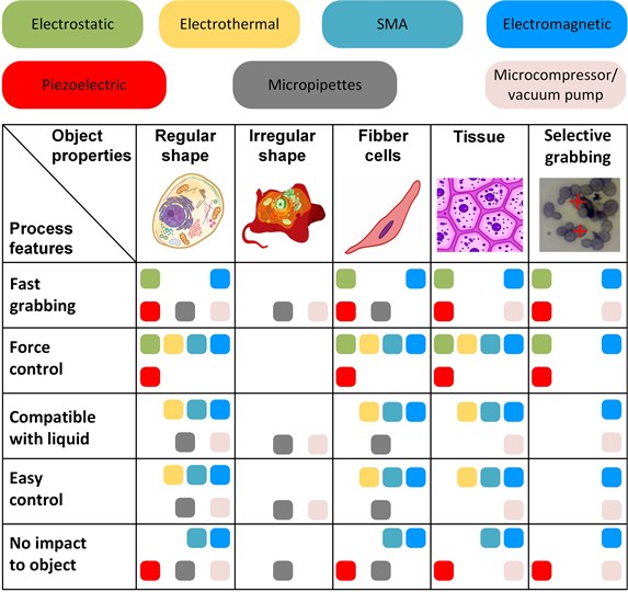
Performed analysis in the field of microgrippers for the manipulation of biological objects revealed interesting features. Different type of biological objects requires the implementation of special gripper properties (Fig. 5). Typical micromanipulation tasks deal with regular/irregular shapes, individual fibber cells, tissues, and the distinction of a single cell from the group of cells. Figure 5 presents the suitability of the grippers according to the shape and size of the object, its mechanical properties, and environmental conditions (e.g. aqueous media). The impact of their parameters limits the application of the grippers to the object, including actual voltage on the gripper jaws and jaws temperature from the operation of actuators.
The grabbing of objects with irregular shapes is the most complicated one due to the lack of parallel surfaces for the clamping in the jaws. Therefore, using micropipettes or vacuum grippers to manipulate this type of object seems to be the most practical solution. The other difficult case is selective grabbing due to the required fast response of the gripper. Especially electromagnetic and vacuum fits this task due to fast operation and ability to operate in liquids. However, vacuum grippers cannot control gripping force.
In general, regular shape, fibber cells, and tissue are suitable to manipulate using a majority of the grippers. However, the actual manipulation task brings special limitations, such as grabbing speed, actual grabbing force, object sensitivity to the external impact, and available equipment. One of the essential limitations is object sensitivity to the impact created by the grabbing process; for example, using a thermoelectric gripper creates the danger of raising object temperature over the acceptable limit. Biological objects are also sensitive to accidentally appearing voltage on the jaws; this voltage can damage or kill living cells. Therefore, if the gripper operates at high voltage, the design must contain extended arms to distant biological objects from the actuators.
Despite the comprehensive coverage of the field of biological object manipulation, new challenges and tasks still appear and need a solution.
Fig. 5The outcome of microgripper analysis according to their functions and application
8. Conclusions
Comprehensive analysis of available microgrippers for manipulating living cells revealed the applicability of the microgrippers in the area of microrobotics. There are frequent mentioning of the electrostatic, shape memory alloy, electromagnetic, piezoelectric and vacuum grippers; other types are not applicable in this area of research by size or due to incompatibility with live cells. Analysis reveals their advantages and disadvantages, therefore possible implementation area, size and shape of the grabbing object defined in the big picture of the review. There are possible some other direction of analysis on the grippers, but presented result summarized effort in the form of systematic approach. For example, nonlinear electrostatic microgripper with an integrated force sensor can manipulate the smallest living cells, i.e. 1-30 µm, but practical use of these grippers in real biological and medical research is still quite rare. Electromagnetic and piezoelectric devices have the fastest gripping process, but they cannot operate in aqueous medium or faces strict limitations there. Concluding analysis of this review, it is possible to state:
1) Every application need separate case analysis, but restrictions are clear and general;
2) Decreasing irregularity of the cells harshly limits amount of solutions for grabbing, so robotic manipulation possibly need some technical grabbing transformation or physical or chemical fixture;
3) There is no gripper, suitable for all types of cells and respecting all physical conditions;
4) There is an open area of scientific research and engineering design of the grippers for recent medical and biological applications;
5) Big prospective open for implementing of new materials, phaenomena and control technologies in the area of microrobotics and microgrippers in particular.
References
-
J. K. Luo et al., “Modelling and fabrication of low operation temperature microcages with a polymer/metal/DLC trilayer structure,” Sensors and Actuators A: Physical, Vol. 132, No. 1, pp. 346–353, Nov. 2006, https://doi.org/10.1016/j.sna.2006.03.004
-
R. Zhang, J. Chu, L. Guan, S. Li, and J. Min, “Microgripping force measuring device based on SU-8 microcantilever sensor,” Journal of Micro/Nanolithography, MEMS, and MOEMS, Vol. 13, No. 1, p. 013007, Feb. 2014, https://doi.org/10.1117/1.jmm.13.1.013007
-
A. Dochshanov, M. Verotti, and N. P. Belfiore, “A comprehensive survey on microgrippers design: operational strategy,” Journal of Mechanical Design, Vol. 139, No. 7, Jul. 2017, https://doi.org/10.1115/1.4036352
-
V. Bučinskas, J. Subačiūtė-Žemaitienė, A. Dzedzickis, and I. Morkvėnaitė-Vilkončienė, “Robotic micromanipulation: a) actuators and their application,” Robotic Systems and Applications, Vol. 1, No. 1, pp. 2–23, Jun. 2021, https://doi.org/10.21595/rsa.2021.22071
-
M. Boudaoud, Y. Haddab, and Y. Le Gorrec, “Modelling of a MEMS-based microgripper: application to dexterous micromanipulation,” in 2010 IEEE/RSJ International Conference on Intelligent Robots and Systems (IROS 2010), pp. 5634–5639, Oct. 2010, https://doi.org/10.1109/iros.2010.5650553
-
A. Areas, “FT-G32 Force Sensing Microgripper”.
-
A. A. Felix, D. Colón, B. M. Verona, L. W. S. L. Ramos, H. Cobas-Gomez, and M. R. Gongora-Rubio, “Identification and robust controllers for an electrostatic microgripper,” Journal of Vibration Engineering and Technologies, Vol. 9, No. 3, pp. 389–397, Apr. 2021, https://doi.org/10.1007/s42417-020-00241-2
-
M. Boudaoud, Y. Haddab, and Y. Le Gorrec, “Modeling and optimal force control of a nonlinear electrostatic microgripper,” IEEE/ASME Transactions on Mechatronics, Vol. 18, No. 3, pp. 1130–1139, Jun. 2013, https://doi.org/10.1109/tmech.2012.2197216
-
C.-J. Kim, A. P. Pisano, and R. S. Muller, “Silicon-processed overhanging microgripper,” Journal of Microelectromechanical Systems, Vol. 1, No. 1, pp. 31–36, Mar. 1992, https://doi.org/10.1109/84.128053
-
Y. Jia, M. Jia, and Q. Xu, “A dual-axis electrostatically driven MEMS microgripper,” International Journal of Advanced Robotic Systems, Vol. 11, No. 11, p. 187, Nov. 2014, https://doi.org/10.5772/59677
-
G. Greitmann and R. A. Buser, “Tactile microgripper for automated handling of microparts,” Sensors and Actuators A: Physical, Vol. 53, No. 1-3, pp. 410–415, May 1996, https://doi.org/10.1016/0924-4247(96)80164-6
-
F. Beyeler et al., “Monolithically fabricated microgripper with integrated force sensor for manipulating microobjects and biological cells aligned in an ultrasonic field,” Journal of Microelectromechanical Systems, Vol. 16, No. 1, pp. 7–15, Feb. 2007, https://doi.org/10.1109/jmems.2006.885853
-
K. Amjad, S. A. Bazaz, and Y. Lai, “Design of an electrostatic MEMS microgripper system integrated with force sensor,” in 2008 International Conference on Microelectronics – ICM, pp. 236–239, Dec. 2008, https://doi.org/10.1109/icm.2008.5393544
-
G. Yuan, W. Yuan, Y. Hao, X. Li, and H. Chang, “A microgripper with a post-assembly self-locking mechanism,” Sensors, Vol. 15, No. 8, pp. 20140–20151, Aug. 2015, https://doi.org/10.3390/s150820140
-
A. A. Abbasi and M. T. Ahmadian, “Force controlled manipulation of biological cells using a monolithic MEMS based nano-micro gripper,” in ASME 2012 International Mechanical Engineering Congress and Exposition, pp. 193–201, Nov. 2012, https://doi.org/10.1115/imece2012-85019
-
E. Gaafar and M. Zarog, “A low-stress and low temperature gradient microgripper for biomedical applications,” Microsystem Technologies, Vol. 23, No. 12, pp. 5415–5422, Dec. 2017, https://doi.org/10.1007/s00542-017-3325-9
-
M. Verotti, P. Di Giamberardino, N. P. Belfiore, and O. Giannini, “A genetic algorithm-based method for the mechanical characterization of biosamples using a MEMS microgripper: numerical simulations,” Journal of the Mechanical Behavior of Biomedical Materials, Vol. 96, pp. 88–95, Aug. 2019, https://doi.org/10.1016/j.jmbbm.2019.04.023
-
L. Velosa-Moncada, L. Aguilera-Cortés, M. González-Palacios, J.-P. Raskin, and A. Herrera-May, “Design of a novel MEMS microgripper with rotatory electrostatic comb-drive actuators for biomedical applications,” Sensors, Vol. 18, No. 5, p. 1664, May 2018, https://doi.org/10.3390/s18051664
-
N. Chronis and L. P. Lee, “Electrothermally activated SU-8 microgripper for single cell manipulation in solution,” Journal of Microelectromechanical Systems, Vol. 14, No. 4, pp. 857–863, Aug. 2005, https://doi.org/10.1109/jmems.2005.845445
-
Keekyoung Kim, Xinyu Liu, Yong Zhang, and Yu Sun, “MicroNewton force-controlled manipulation of biomaterials using a monolithic MEMS microgripper with two-axis force feedback,” in 2008 IEEE International Conference on Robotics and Automation. The Half-Day Workshop on: Towards Autonomous Agriculture of Tomorrow, pp. 3100–3105, May 2008, https://doi.org/10.1109/robot.2008.4543682
-
K. Kim, X. Liu, Y. Zhang, and Y. Sun, “Nanonewton force-controlled manipulation of biological cells using a monolithic MEMS microgripper with two-axis force feedback,” Journal of Micromechanics and Microengineering, Vol. 18, No. 5, p. 055013, May 2008, https://doi.org/10.1088/0960-1317/18/5/055013
-
M. Kohl, B. Krevet, and E. Just, “SMA microgripper system,” Sensors and Actuators A: Physical, Vol. 97-98, pp. 646–652, Apr. 2002, https://doi.org/10.1016/s0924-4247(01)00803-2
-
K. C. Munasinghe et al., “New MEMS based micro gripper using SMA for micro level object manipulation and assembling,” in 2016 Moratuwa Engineering Research Conference (MERCon), pp. 36–41, Apr. 2016, https://doi.org/10.1109/mercon.2016.7480112
-
M. Garcés-Schröder, L. Hecht, A. Vierheller, M. Leester-Schädel, M. Böl, and A. Dietzel, “Micro-grippers with femtosecond-laser machined in-plane agonist-antagonist SMA actuators integrated on wafer-level by galvanic riveting,” Eurosensors, Vol. 1, No. 10, p. 385, Aug. 2017, https://doi.org/10.3390/proceedings1040385
-
J. H. Kyung, B. G. Ko, Y. H. Ha, and G. J. Chung, “Design of a microgripper for micromanipulation of microcomponents using SMA wires and flexible hinges,” Sensors and Actuators A: Physical, Vol. 141, No. 1, pp. 144–150, Jan. 2008, https://doi.org/10.1016/j.sna.2007.07.013
-
Y. Q. Fu, J. K. Luo, A. J. Flewitt, and W. I. Milne, “Smart microgrippers for bioMEMS applications,” MEMS for Biomedical Applications, pp. 291–336, 2012, https://doi.org/10.1533/9780857096272.3.291
-
M. Cauchi, I. Grech, B. Mallia, P. Mollicone, and N. Sammut, “Analytical, numerical and experimental study of a horizontal electrothermal MEMS microgripper for the deformability characterisation of human red blood cells,” Micromachines, Vol. 9, No. 3, p. 108, Mar. 2018, https://doi.org/10.3390/mi9030108
-
B. Solano and D. Wood, “Design and testing of a polymeric microgripper for cell manipulation,” Microelectronic Engineering, Vol. 84, No. 5-8, pp. 1219–1222, May 2007, https://doi.org/10.1016/j.mee.2007.01.153
-
Xinyu Liu, K. Kim, Yong Zhang, and Yu Sun, “Nanonewton force sensing and control in microrobotic cell manipulation,” The International Journal of Robotics Research, Vol. 28, No. 8, pp. 1065–1076, Aug. 2009, https://doi.org/10.1177/0278364909340212
-
N. Chronis and L. P. Lee, “Polymer MEMS-based microgripper for single cell manipulation,” in 17th IEEE International Conference on Micro Electro Mechanical Systems. Maastricht MEMS 2004 Technical Digest, 2004, https://doi.org/10.1109/mems.2004.1290511
-
M. Cauchi, I. Grech, B. Mallia, P. Mollicone, and N. Sammut, “The effects of cold arm width and metal deposition on the performance of a U-beam electrothermal MEMS microgripper for biomedical applications,” Micromachines, Vol. 10, No. 3, p. 167, Feb. 2019, https://doi.org/10.3390/mi10030167
-
K. S. Colinjivadi, J.-B. Lee, and R. Draper, “Viable cell handling with high aspect ratio polymer chopstick gripper mounted on a nano precision manipulator,” Microsystem Technologies, Vol. 14, No. 9-11, pp. 1627–1633, Oct. 2008, https://doi.org/10.1007/s00542-008-0580-9
-
H.-Y. Chan and W. J. Li, “A thermally actuated polymer micro robotic gripper for manipulation of biological cells,” in 2003 IEEE International Conference on Robotics and Automation (Cat. No. 03CH37422), 2003, https://doi.org/10.1109/robot.2003.1241610
-
A. Potekhina, R.-C. Voicu, R. Muller, M. H. M. Al-Zandi, and C. Wang, “Design and characterization of a polymer electrothermal microgripper with a polynomial flexure for efficient operation and studies of moisture effect on negative deflection,” Microsystem Technologies, Vol. 27, No. 7, pp. 2723–2731, Jul. 2021, https://doi.org/10.1007/s00542-020-05086-z
-
A. Somà, S. Iamoni, R. Voicu, R. Müller, M. H. M. Al-Zandi, and C. Wang, “Design and experimental testing of an electro-thermal microgripper for cell manipulation,” Microsystem Technologies, Vol. 24, No. 2, pp. 1053–1060, Feb. 2018, https://doi.org/10.1007/s00542-017-3460-3
-
S. Iamoni and A. Somà, “Design of an electro-thermally actuated cell microgripper,” Microsystem Technologies, Vol. 20, No. 4-5, pp. 869–877, Apr. 2014, https://doi.org/10.1007/s00542-013-2065-8
-
D.-H. Kim, M. G. Lee, B. Kim, and Y. Sun, “A superelastic alloy microgripper with embedded electromagnetic actuators and piezoelectric force sensors: A numerical and experimental study,” Smart Materials and Structures, Vol. 14, No. 6, pp. 1265–1272, Dec. 2005, https://doi.org/10.1088/0964-1726/14/6/019
-
X. Lv, W. Wei, X. Mao, Y. Chen, J. Yang, and F. Yang, “A novel MEMS electromagnetic actuator with large displacement,” Sensors and Actuators A: Physical, Vol. 221, pp. 22–28, Jan. 2015, https://doi.org/10.1016/j.sna.2014.10.028
-
Y. Jia and Q. Xu, “MEMS Microgripper Actuators and Sensors: The State-of-the-Art Survey,” Recent Patents on Mechanical Engineering, 2013.
-
J. Zhang, O. Onaizah, K. Middleton, L. You, and E. Diller, “Reliable grasping of three-dimensional untethered mobile magnetic microgripper for autonomous pick-and-place,” IEEE Robotics and Automation Letters, Vol. 2, No. 2, pp. 835–840, Apr. 2017, https://doi.org/10.1109/lra.2017.2657879
-
T.-R. Ger, H.-T. Huang, W.-Y. Chen, and M.-F. Lai, “Magnetically-controllable zigzag structures as cell microgripper,” Lab on a Chip, Vol. 13, No. 12, p. 2364, 2013, https://doi.org/10.1039/c3lc50287b
-
R. Zhao and Q. Lu, “Design and experiments of a Galfenol composite cantilever beam-driven magnetostrictive micro-gripper,” Iranian Journal of Science and Technology, Transactions of Mechanical Engineering, Vol. 44, No. 1, pp. 1–10, Mar. 2020, https://doi.org/10.1007/s40997-018-0244-z
-
M. N. M. Zubir, B. Shirinzadeh, and Y. Tian, “Development of a novel flexure-based microgripper for high precision micro-object manipulation,” Sensors and Actuators A: Physical, Vol. 150, No. 2, pp. 257–266, Mar. 2009, https://doi.org/10.1016/j.sna.2009.01.016
-
S. K. Nah and Z. W. Zhong, “A microgripper using piezoelectric actuation for micro-object manipulation,” Sensors and Actuators A: Physical, Vol. 133, No. 1, pp. 218–224, Jan. 2007, https://doi.org/10.1016/j.sna.2006.03.014
-
Q. Xing and Y. Ge, “Parametric study of a novel asymmetric micro-gripper mechanism,” Journal of Advanced Mechanical Design, Systems, and Manufacturing, Vol. 9, No. 5, pp. JAMDSM0075–JAMDSM0075, 2015, https://doi.org/10.1299/jamdsm.2015jamdsm0075
-
X. Chen, Z. Deng, S. Hu, J. Gao, and X. Gao, “Design of a compliant mechanism based four-stage amplification piezoelectric-driven asymmetric microgripper,” Micromachines, Vol. 11, No. 1, p. 25, Dec. 2019, https://doi.org/10.3390/mi11010025
-
T. K. Das, B. Shirinzadeh, M. Ghafarian, A. Al-Jodah, and J. Pinskier, “Characterization of a compact piezoelectric actuated microgripper based on double-stair bridge-type mechanism,” Journal of Micro-Bio Robotics, Vol. 16, No. 1, pp. 79–92, Jun. 2020, https://doi.org/10.1007/s12213-020-00132-5
-
T. Kumar Das, B. Shirinzadeh, A. Al-Jodah, M. Ghafarian, and J. Pinskier, “A novel compliant piezoelectric actuated symmetric microgripper for the parasitic motion compensation,” Mechanism and Machine Theory, Vol. 155, p. 104069, Jan. 2021, https://doi.org/10.1016/j.mechmachtheory.2020.104069
-
T. Abondance, K. Jayaram, N. T. Jafferis, J. Shum, and R. J. Wood, “Piezoelectric grippers for mobile micromanipulation,” IEEE Robotics and Automation Letters, Vol. 5, No. 3, pp. 4407–4414, Jul. 2020, https://doi.org/10.1109/lra.2020.2997317
-
D. Petrovic et al., “Gripping tools for handling and assembly of microcomponents,” in 2002 23rd International Conference on Microelectronics. Proceedings (Cat. No.02TH8595), 2002, https://doi.org/10.1109/miel.2002.1003186
-
K. Takahashi, H. Kajihara, M. Urago, S. Saito, Y. Mochimaru, and T. Onzawa, “Voltage required to detach an adhered particle by Coulomb interaction for micromanipulation,” Journal of Applied Physics, Vol. 90, No. 1, pp. 432–437, Jul. 2001, https://doi.org/10.1063/1.1379353
-
W. Zesch, M. Brunner, and A. Weber, “Vacuum tool for handling microobjects with a nanorobot,” in Proceedings of International Conference on Robotics and Automation, 1997, https://doi.org/10.1109/robot.1997.614405
-
W. Rong, Z. Fan, L. Wang, H. Xie, and L. Sun, “A vacuum microgripping tool with integrated vibration releasing capability,” Review of Scientific Instruments, Vol. 85, No. 8, p. 085002, Aug. 2014, https://doi.org/10.1063/1.4891695
-
D. G. Urbano, G. Noventa, A. Ghidoni, and A. M. Lezzi, “A semi-empirical fluid dynamic model of a vacuum microgripper based on CFD analysis,” Applied Sciences, Vol. 11, No. 16, p. 7482, Aug. 2021, https://doi.org/10.3390/app11167482
-
Y. Anis, J. Houkal, M. Holl, R. Johnson, and D. Meldrum, “Diaphragm pico-liter pump for single-cell manipulation,” Biomedical Microdevices, Vol. 13, No. 4, pp. 651–659, Aug. 2011, https://doi.org/10.1007/s10544-011-9535-5
About this article

This project has received financial support from the Research Council of Lithuania (LMTLT), No. P-LLT-21-6, State Education Development Agency of Latvia, Ministry of Science and Technology (MOST) of Taiwan.
