Abstract
The design of an intelligent exoskeleton robot with pneumatic artificial muscles for human lower limb motion assist using electromyography (EMG) is presented. There are four topics addressed in this paper. Decoding electromyography is the first topic. When muscles are active, they produce an electrical activity. EMG is a record of this electrical activity that reflects human’s movement. Through regression analysis a model is obtained to extract motion commands from EMG. It would be an advantage to employ EMG as a control signal for the exoskeleton control. Second, the pneumatic artificial muscle, air muscle for short, is a simple and powerful actuator. When actuated with compressed air, it contracts and provides a pulling force. As a result of its behavior in a similar way to a biological muscle, air muscle is adapted for a bionic actuator of the assist robot. The force models of air muscles are investigated by experiments in a workbench. Third, for the control of a bionic-inspired robot, the multimodal sensory feedback including EMG and inertial sensors is necessary. By using EMG as a force-proportional measurement between human and robot, a control system combined a sensor-fusion approach and a compliant mechanism enables exoskeleton to carry out human-robot collaboration. Finally, a prototype of power-assist exoskeleton robot for lower limb is completed and evaluated by experiments successfully.
1. Introduction
A powered exoskeleton is very important for those who lose the ability to move. Pneumatic artificial muscle, called air muscle in short, is very suited for providing the necessary power or force of an exoskeleton. Air muscles contain a lot of features: lightweight, smooth action, flexible, excellent power to weight ratio, and compliant. Especially the inherent compliance makes air muscles become “soft” actuators that are suitable for safer mechanism and actuator design. In addition, air muscles work like biological muscles. The air muscle contracts and producing a pulling force as actuated with a supply of compressed air. We can control the pressure to obtain desired force to manipulate the exoskeleton. Four common models of air muscles including geometrical model, phenomenological biomechanical model, curved model, and empirical model of air muscles are surveyed in [1]. The theoretical and experimental work about modeling of air muscles has been addressed in [2, 3]. A sliding-mode control approach is also successfully used to design the control of robot arms actuated by air muscles [3]. It points out that the soft nature of air muscles seems to limit its accuracy but it adapts well to the moderate speed and accuracy required in service robots as well as bionic-inspired robots.
How to build a “bionic-inspired” exoskeleton robot? Electromyogram is one of the promising biological signals suited to wearable technology application. Electromyogram is a tiny electrical signal originated from physiological variations in the state of muscle fiber membranes [4]. It gives an access to neuromuscular activation of muscles from EMG.
The raw EMG spikes are of random shape, which cannot be precisely reproduced in exact shape. To solve the problem, the moving average smoothing algorithm is an effective method to minimize the un-reproducible part and outline the trend of EMG. As a result of smoothing, a linear envelope of EMG is obtained that becomes a feasible waveform revealing the kinematics and kinetics information of limbs.
Some EMG-driven musculoskeletal models were proposed to estimate muscle forces and joint movements from EMG [5, 6]. Unfortunately, these models are too complicated to be a good choice in using electromyogram as a decisive signal for the exoskeleton control. A regression model to predict joint moments from EMG and joint angles is as simple as reasonable that has the potential in control applications [7]. The linear envelope profile of raw EMG which resembles the muscle tension waveform is multiplied by a gain to become a force set-point that is successfully used to control a powered exoskeleton, called a proportional EMG control [8]. Sun et al incorporate impedance control and fuzzy logic control into the experiment of a horizontal lower limbs rehabilitation robot [9]. The last two papers [8] and [9] give an idea to use EMG as a force-oriental biological feedback and design an impedance control system for bionic-inspired exoskeleton in this paper.
2. Air muscle modeling
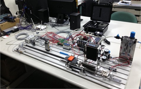
We use the Festo fluidic muscles DMSP to provide tensile actuation which mimic natural human muscle behavior. A workbench for air muscle testing is built as shown in Fig. 1. In this workbench there are load cell sensor, linear potentiometer, data acquisition device, mechanism, and PC. The modeling work of air muscles is conducted in this workbench.
Fig. 1A workbench for air muscle testing
In order to quantitatively analyze the system behavior, the transfer function is constructing. The transfer function is a representation of a system from input to output. Often it is not easy to obtain a system’s transfer function analytically; however, it is practical to complete this work via testing [10]. A useful method is to analyze the system’s step response. One end of an air muscle is fixed to a metal seat on the workbench, and the other end is connected to a parallel spring assembly which is fixed to another metal seat on the workbench. In a quasi-static condition, given a step pressure command from 2 bars to 5 bars as control input, the spring displacement is recorded by the linear potentiometer in workbench shown in Fig. 1 and then multiplied by spring constant to be equal to the force output. From Fig. 2 the waveform of step response is similar to that of a first-order system, such as no overshoot. Since the steady-state value is about 100, we can evaluate the time constant where the force curve reaches 63% × 100 = 63, or about 0.177 second. Hence, the first-order system pole at is calculated by . The step response reaches a final value of . Substituting the value of , we obtain . Thus, a first-order transfer function for the air muscle is approximated as:
where is the force increment, (bar) is the pressure command increment.
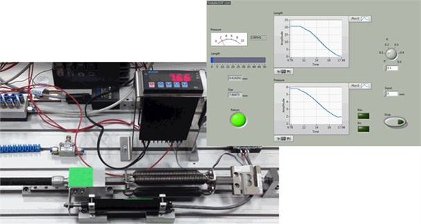
This force model of air muscle is tested in the workbench by performing a closed loop control experiment. The results are in agreement with the model prediction. In our experiment the graphical programming language LabVIEW is adopted to complete data acquisition and control. The code (block diagram) and front panel (man-machine interface) of LabVIEW are shown in Figs. 3-4.
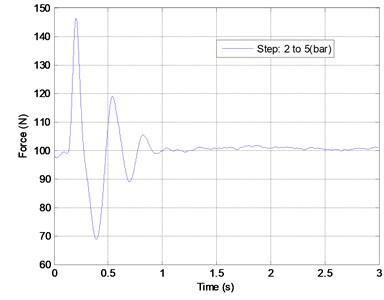
Fig. 2Laboratory results of an air muscle step response (pressure 2 to 5 bar)
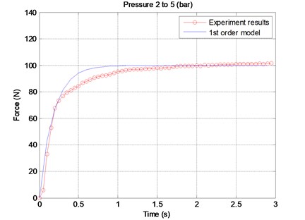
Fig. 3A part of LabVIEW block diagram for air muscle close-loop test in workbench
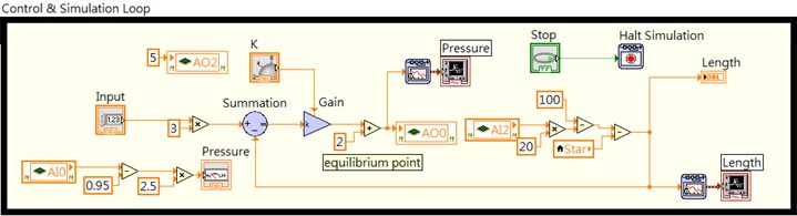
Fig. 4The LabVIEW front panel of close-loop position control of air muscle in workbench
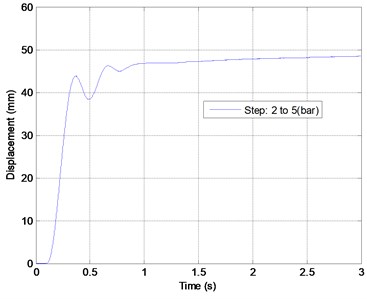
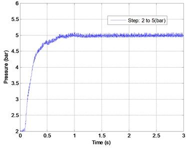
The air muscle is also studied by performing an isotonic contraction in workbench. One end of the air muscle is fixed and the other end is connected to a given load (10 kg) by means of a pulley system. Initially the air muscle is at rest. Once a step pressure input is given, the air muscle contracts and lifts the load until it reaches an equilibrium position. The history of force, displacement, and pressure are recorded as shown in Fig. 5(a)-(c). Through linear regression analysis, the force of air muscle can be expressed as a function of displacement and pressure variation in the following:
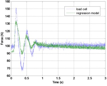
where is the force increment (unit: N), is the displacement increment (unit: contraction %), is the pressure increment (unit: bar). From Fig. 5 (d) the linear regression force model is more accurate in rising stage than in slack stage. If the higher order terms of displacement increment and pressure increment are considered, the results of force model are improved.
Fig. 5A regression analysis for air muscle force, displacement, and pressure
a)
b)
c)
d)
3. Exoskeleton design
A commercially available exoskeleton is redesigned to fit the air muscles allocation. One pivot above knee joint and two half-ring supports on thigh and lower leg are added into the new configuration. The engineer drawing and a prototype exoskeleton equipped with air muscles are shown in Fig. 6. From trigonometry, the theoretical relation of air muscle (corresponding to rectus femoris) length and knee joint angle of exoskeleton can be obtained. For convenience in the following control design, a first-degree polynomial curve by regression fitting the theoretic results very well is used. The amplitude scaling function is:
where is the displacement increment (unit: contraction %), is the knee joint angle (unit: rad).
4. EMG processing
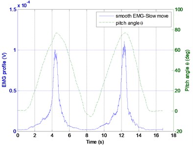
A subject sit on the desk and fixes his thigh, and is asked to perform leg extension/flexion exercise periodically as shown in Fig. 7. The Delsys Trigno wireless EMG sensor and Xsens MTw motion tracker are used to sense the EMG and knee joint pitch angle. The raw EMG data are processing by rectification, moving average smoothing, normalization, and finally regression as shown in Fig. 8. The five-degree polynomial regression function is derived from EMG envelope and joint pitch angle profile expressed as:
where is the pitch angle (unit: deg), is the profile of EMG envelope by moving average smoothing under 500 points span approximately 0.25 sec. According Eq. (4) the EMG profile can be transferred to the desired joint pitch angle that reflects human movement intention.
Fig. 6An exoskeleton from design to a prototype
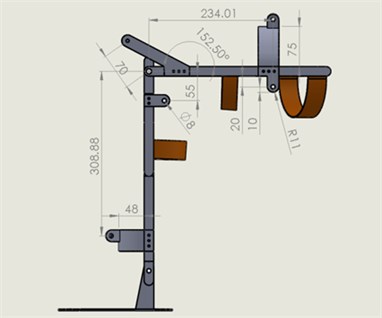
a) Engineer drawing
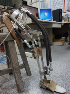
b) Exoskeleton equipped with air muscles
Fig. 7Collecting EMG data from a subject performing periodic extension/flexion exercise
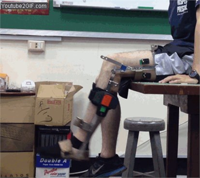
Fig. 8EMG processing and regression model verification
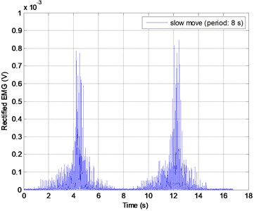
a) Rectification
b) Moving average smooth
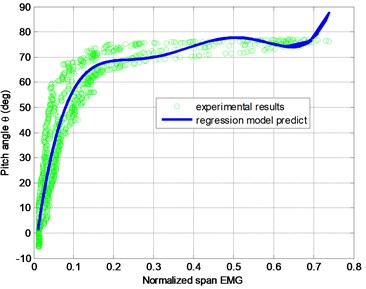
c) Pitch angle vs. normalized EMG
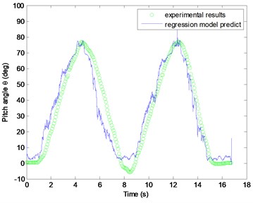
d) Pitch angle history
5. Control of wearable exoskeleton
Ignoring the friction loss, the dynamical equation of an exoskeleton is expressed as:
where (Nms2/rad), (kg), and (m) denote the inertia, mass, length of c.g. of exoskeleton, (m/s2) is the gravity constant, and (m/s2) denotes the torque applied by the exoskeleton. By feedback linearization, the applied torque is computed to be:
then a resulting linear equation becomes:
It enables us to use linear analysis techniques to design a PI controller for . The parameters of PI controller are chosen to be 0.02, 0.14.
As for the nonlinear term from gravity, it can be compensated according to the specified pitch angle. In practice the control signal is the pressure command to air muscles which is composed of and written as:
where represents the static part of pressure command for sustaining at different equilibrium pitch angles, and represents the dynamic part from PI controller to compensate the pitch angle error. A first degree linear model of is derived from approximating to the experiment data as shown in Fig. 9 and is expressed as:
The big picture of control system is shown in Fig. 10.
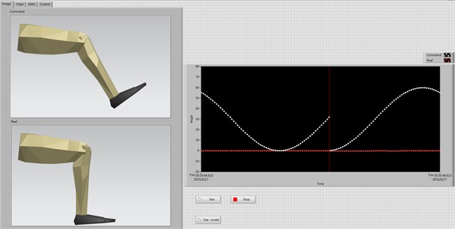
A subject wearing the exoskeleton watches the sinusoidal guidance on the screen and performs leg exercise as shown in Figs. 11-12.
Fig. 9Pressure vs. pitch angle in static equilibrium
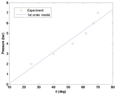
Fig. 10The block diagram of control system for bionic-inspired exoskeleton
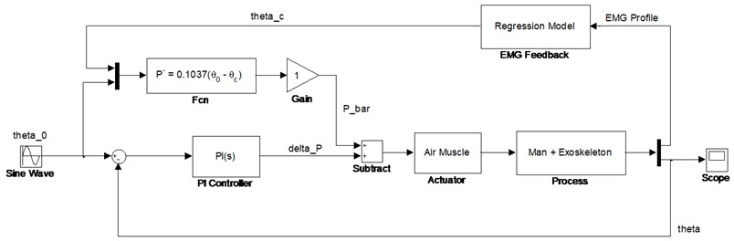
Fig. 11A subject wearing exoskeleton performing periodic leg exercise
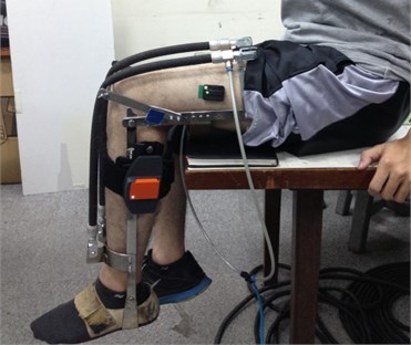
Fig. 12A video guidance on the screen for leg exercise
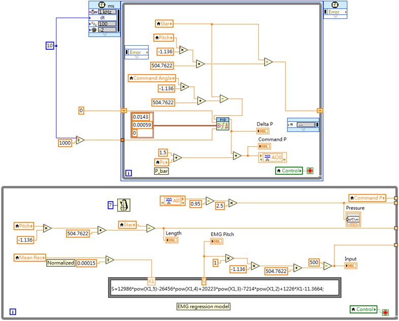
A part of LabVIEW block diagram for exoskeleton control is also shown in Fig. 13.
Fig. 13A part of LabVIEW block diagram for exoskeleton control
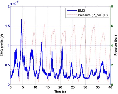
The results of experiment are shown in Figs. 14-16. In Fig. 14 it is clear that the sinusoidal leg exercise is completed even if the subject exerts little effort to move his leg. Imagine a scenario that a patient is unable to move his leg by himself. It is benefit to him to exercise his leg regularly for rehabilitation with the exoskeleton assist. Next, Fig. 15 illustrates the fact of saving effort with the help of exoskeleton. Finally, we can see a trade-off between the EMG profile (human muscle effort) and pressure of air muscle (air muscle effort) in Fig. 16. That shows a good synergy in human-robot collaboration.
Fig. 14Time history of exoskeleton pitch angle
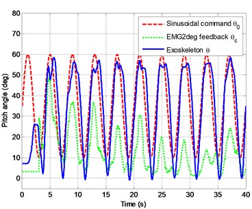
Fig. 15The EMG profiles of a subject with or without exoskeleton assist in exercise
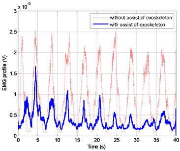
Fig. 16A trade-off between human muscle effort (EMG) and air muscle pressure
6. Conclusions
The paper describes a design process of a bionic-inspired exoskeleton robot including the force modeling of air muscles, exoskeleton reform, EMG processing, and control system design. Three key features of the bionic-inspired exoskeleton are: 1) a safer actuation, which can gently provide the pulling force by using air muscles with inherent compliance; 2) a smart sensor-fusion feedback, which can reach the compatibility between human and exoskeleton by using the biological signal (EMG) to complement inertial information; 3) an effective system, which provides a practical mechanically motion-assist for persons with lower limb deficiency. The experimental results are presented to show the effectiveness of the bionic-inspired exoskeleton.
References
-
Kelasidi E., Andrikopoulos G., Nikolakopoulos G., Manesis S. A survey on pneumatic muscle actuators modeling. IEEE International Symposium on Industrial Electronics, 2011, p. 1263-1269.
-
Chou C.-P., Hannaford B. Measurement and modeling of McKibben pneumatic artificial muscles. IEEE Transactions on Robotics and Automation, Vol. 12, Issue 1, 1996, p. 90-106.
-
Tondu B., Lopez P. Modeling and control of McKibben artificial muscle robot actuators. IEEE Control Systems Magazine, Vol. 20, 2, p. 15-38.
-
Basmajian J. V., De Luca C. J. Muscles Alive-Their Function Revealed by Electromyography. Williams Wilkins, Baltimore, 1985.
-
Lloyd D. G., Besier T. F. An EMG-driven musculoskeletal model to estimate muscle forces and knee joint moments in vivo. Journal of Biomechanics, Vol. 36, 2003, p. 765-776.
-
Buchanan T.S., Lloyd D. G., Manal K., Besier T. F. Neuromusculoskeletal modeling: estimation of muscle forces and joint moments and movements from measurements of neural command. Journal of Applied Biomechanics, Vol. 20, Issue 4, 2004, p. 367-395.
-
Sun Y.-P., Yen K.-T., Liang Y.-C., Wu L.-N., Lu K.-C. An EMG-driven model to estimate knee joint moment. Life Science Journal, Vol. 10, Issue 2, 2013, p. 249-253.
-
Lenzi T., De Rossi S. M. M., Vitiello N., Carrozza M. C. Proportional EMG control for upper-limb powered exoskeletons. 33rd Annual International Conference of the IEEE EMBS, Boston, Massachusetts USA, 2011, p. 628-631.
-
Sun H., Zhang L., Hu X., Tian L. Experiment study of fuzzy impedance control on horizontal lower limbs rehabilitation robot. International Conference on Electronics, Communications and Control, 2011, p. 2640-2643.
-
Nise N. S. Control Systems Engineering. 5th Edition, John Wiley and Sons, 2008.
About this article

