Abstract
Parallel manipulator is one of the areas of research extensively studied by many researchers from past 4-5 decades. Unlike their serial counterparts, parallel manipulators exhibit higher rigidity and controllability when operating at higher speeds. These attributes lead to their application in various fields such as machine tools, simulators and positioning systems. Present work is proposing a modified reconfigurable Dodecapod parallel manipulator. 3D model of the proposed manipulator is successfully developed and kinematics analysis is carried out. Re-configurable sliders are provided to vary the workspace as required. A few illustrative examples are demonstrated for various locations of slider, showing changes in workspace. The novelty of the present manipulator overcomes the workspace limitations of the general Stewart Gough manipulator. Present modified Dodecapod parallel manipulator is capable of improving local kinematic performance.
1. Introduction
The limitations of serial manipulators have motivated many researchers to investigate more on parallel manipulators. Parallel manipulators are an active research area over the past four to five decades for their various advantages viz., higher stiffness, higher precision and better dynamic capacities at high velocities. A Parallel manipulator is a combination of independent closed loop kinematic chains connecting a fixed base platform and a movable top platform. They are used for various applications like satellite positioning, aircraft simulators, precision requiring tasks like assembly of PCBs etc., Gough [1] introduced, for the first time, a platform with six actuated legs. He used it as a Universal Tyre Testing Machine. Stewart [2] invented the manipulator in the form of a flight simulator which ignited a new promising topic of research due to its inheriting advantages. It later gained popularity in the name of Stewart manipulator and is sometimes called as Stewart-Gough on account of Gough being its original inventor. Hunt [3] was the first to recognise the significance of parallel manipulators. Stewart Manipulator was studied in depth by researchers in the 1990s. Dasgupta [4] presented a detailed review of the work carried out on Stewart platforms until the year 2000. Furqan [5] extended the review until the year 2017.
Initially parallel manipulators found very restricted applications in industries due to their complex forward kinematics and limited workspace. Singularities within the workspace lead to loss or unwanted gain in stiffness which might make them uncontrollable. Many researchers have worked extensively in designing parallel manipulators which overcome these limitations. Workspace limitations are known to reduce by introducing re-configurability in parallel manipulators. This is achieved by modifying the configuration of the parallel manipulator. Bande [6] presented a 12 DOF parallel manipulator, called Dodecapod. A Dodecapod is a Hexapod with variable workspace. The six additional degrees of freedom are available from the movement of top and bottom mobile knots. Mishra [7] showed how to maximize tilt angle with change in the configuration of the Dodecapod. Inverse and forward kinematic analysis of the Dodecapod in [6] is restricted to position kinematics. In addition, actuation of mobile knots is not straight forward.
Present work reports a novel modified reconfigurable Dodecapod. A 3D model of a modified reconfigurable Dodecapod is designed and developed using SolidWorks. Provisions are made to provide independent movement of the sliders. Mathematical model is developed and is capable of generating kinematic solution of the mechanism. The workspace for various configurations of the top platform is generated and reported. The workspace limitation of the general Stewart-Gough manipulator is overcome by change in configurations of the Dodecapod. A detailed inverse position, velocity and acceleration kinematic formulations are derived and analysed. Author decided to report this work in a detailed journal paper. Lastly, a few suggestions are made highlighting the possible potential the manipulator.
2. Model description
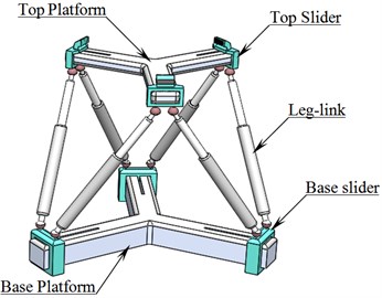
A 3D model of a modified reconfigurable Dodecapod parallel manipulator is shown in Fig. 1. It is a reconfigurable manipulator, consists of two platforms viz., top-platform and base-platform. Platforms are connected to each other by means of six links, named as leg-links. Leg-links are connected to top and base platforms by means of spherical joints provided with the sliders. Leg-links are provided with linear prismatic actuators and they provide spatial motion to the top platform.
Fig. 13D model of the Dodecapod
The Platforms consist of three arms 120° apart. Each arm houses a slider which slides along a slot. Position of each slider is controlled by prismatic actuators (pistons) embedded in the arms of the platforms, as shown in Fig. 2.
Fig. 2Internal actuators in each arm
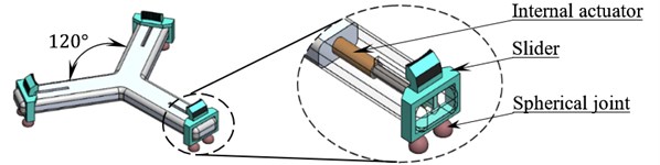
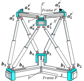
Fig. 3 shows a schematic diagram of a kinematic analysis of Dodecapod. Two cartesian coordinate frames viz., and are defined to describe the system. The coordinate frame remains fixed to the stationary base of the manipulator and the coordinate frame is attached to the moving top-platform of the manipulator. A set of position vectors for the joints at the top platform are defined with respect the frame and is denoted by . A set of position vectors for joints at the base with respect to is denoted by. As the frame moves with the top platform joint vector remains constant even though the actual coordinate of joints changes.
Fig. 3Kinematic diagram of Dodecapod
The coordinates of the joints are expressed as:
where, and are radial distances of spherical joints of the sliders to the centre of the top and the base platform respectively. , and , are constant vectors which depend on the geometry of the base and top platform respectively. For the model shown in Fig. 1 the vectors , , and are shown in Table 1.
A Cartesian coordinate vector is used to define the position and orientation of the top platform. Coordinates () describes the position the center of the top platform and () are the Euler’s angles describes the orientation of the top platform.
Table 1Coordinates of cai, sai, cbi and sbi
Coordinates of | Coordinates of (in mm) | |||||||||||
0.50 | 0.50 | 0.50 | –1.00 | –1.00 | 0.50 | 5.41 | 5.41 | -5.41 | 0.00 | 0.00 | –5.41 | |
–0.87 | 0.87 | 0.87 | 0.00 | 0.00 | -0.87 | 3.13 | –3.13 | 3.13 | 6.25 | –6.25 | –3.13 | |
0.00 | 0.00 | 0.00 | 0.00 | 0.00 | 0.00 | –7.45 | –7.45 | –7.45 | –7.45 | –7.45 | –7.45 | |
Coordinates of (in mm) | Coordinates of (in mm) | |||||||||||
1.00 | 1.00 | –0.50 | –0.50 | –0.50 | –0.50 | 0.00 | 0.00 | 8.66 | –8.66 | –8.66 | 8.66 | |
0.00 | 0.00 | 0.87 | 0.87 | –0.87 | –0.87 | –10.00 | 10.00 | 5.00 | –5.00 | 5.00 | –5.00 | |
0.00 | 0.00 | 0.00 | 0.00 | 0.00 | 0.00 | 10.26 | 10.26 | 10.26 | 10.26 | 10.26 | 10.26 | |
3. Workspace and kinematic analysis
Workspace of a parallel manipulator is the region of space with which a reference point on the top platform is able to reach. As the motion of a parallel manipulator is constrained by many factors, its workspace is limited. One of the main challenges in the design of a parallel manipulator is to expand its workspace to the larger extend [8]. The various factors which limit the workspace include minimum and maximum limits of link lengths, self-collision of different parts of the manipulator and limits on the rotation of the joints. Due to these factors the workspace of a parallel manipulator is split into many complex shapes which make its analysis very complex [9].
The workspace of an -DOF manipulator is defined by each of its degrees of freedom, which implies that the workspace is in an -dimensional space. For parallel manipulators with more than 3 degrees of freedom, graphical representation of workspace in cartesian space is possible only if the other) degrees of freedom are kept fixed. This leads to the proposal of many types of workspace depending on what parameters are kept fixed. The different types of workspace include: constant orientation workspace, orientation workspace, maximal workspace, Dexterous workspace and singularity-free workspace [10].
To understand the advantages of the proposed manipulator, a few illustrative examples are reported. certain configurations of sliders are considered. The corresponding constant orientation workspace of the manipulator at an orientation of is generated. Motion of the top platform from an initial Cartesian coordinate to a final cartesian coordinate is considered. The motion happens in uniform steps of change in the cartesian coordinate . The resulting linear acceleration and velocity curves of the leg links, for each slider configuration, are generated and compared.
The maximum and minimum lengths of each leg-link are denoted by and . The radial distance from the centre of top platform to its slider is denoted by and the radial distance from the centre of the base platform to its sliders is denoted by . These radial distances are variable independently depending on the position of each of sliders at the top and base platforms. In the following illustrative examples, values of , , , , and are considered as indicated in Table 2.
The maximum tilt angle, for the joints about their symmetric axis is assumed as 45°. Two illustrative examples are demonstrated in the following session, considering various locations for sliders, showing changes in workspace.
Table 2Values of link variables
Notation | ||||||
Dimension (mm) | 155.67 | 94.11 | 65.83 | 40.83 | 90.77 | 50.77 |
3.1. Example 1
Example 1 demonstrates the max-max configuration. Max-max configuration indicates that both and are at their maximum positions as shown in Fig. 4.
Substituting and in Eqs. (1) and (2) respectively, coordinates of the connecting joints at top and base platform are evaluated and tabulated in Table 3.
Fig. 4Max-max system configuration
Fig. 5Workspace for max-max configuration
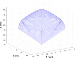
Table 3Coordinates of the joints at top and base platform (in mm)
At top platform | At base platform | |||||||||||
38.33 | 38.33 | 27.50 | –65.83 | –65.83 | 27.50 | 90.77 | 90.77 | –36.72 | –54.05 | –54.05 | –36.72 | |
–53.88 | 53.88 | 60.13 | 6.25 | –6.25 | –60.13 | –10.00 | 10.00 | 83.61 | 73.61 | –73.61 | –83.61 | |
–7.45 | –7.45 | –7.45 | –7.45 | –7.45 | –7.45 | 10.26 | 10.26 | 10.26 | 10.26 | 10.26 | 10.26 | |
The values of and form the basic inputs to compute the velocities and accelerations of leg-links and to generate the workspace. The workspace volume of the max-max configuration is generated and represented in Fig. 5. The volume of the workspace is calculated to be ~1,54,119.71 mm3.
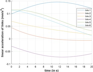
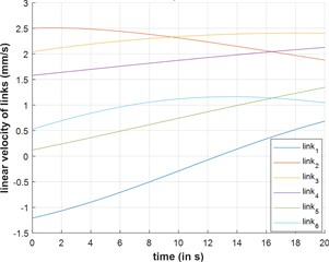
The top platform undergoes actuation from position to . The velocities and acceleration of the leg-links are plotted against time and reported in Fig. 6(a) and 6(b) respectively.
Fig. 6Acceleration and velocity of leg links v/s time
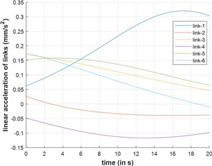
a) Acceleration
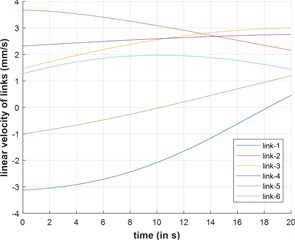
b) Velocity
3.2. Example 2
Example 2 demonstrates the min-min configuration. Min-min configuration indicates that both and are at their min values as shown in Fig. 7.
Fig. 7min-min system configuration
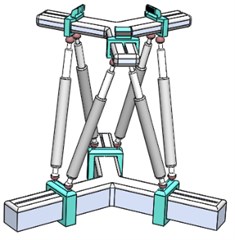
Fig. 8Workspace for min-min configuration
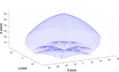
Fig. 9Extensional acceleration and velocity of leg links v/s time
a) Acceleration
b) Velocity
The workspace volume of the max-max configuration is generated and represented in Fig. 8. The volume of the workspace is calculated to be ~6,59,918.70 mm3.
The top platform undergoes linear actuation from position to . The extensional velocities and acceleration of the leg-links are plotted against time and reported in Fig. 9(a) and (b) respectively.
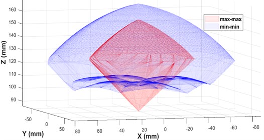
Fig. 10 shows a both max-max and min-min configuration of the proposed modified Dodecapod, showing different volume and different reach for both the configurations. The min-min configuration offers the maximum workspace volume. However, the space coverage is different for each configuration. With change in slider configuration, different workspace can be achieved based on the required space coverage.
Fig. 10Constant orientation workspace of max-max and min-min configuration
4. Conclusions
In this paper, a modified reconfigurable Dodecapod parallel manipulator is reported. Inverse Kinematics of the modified Dodecapod is simple and straight forward. Model description, workspace and kinematic analysis are narrated. The configuration of the manipulator can be adjusted depending on the required reach/workspace. The novelty of the present manipulator overcomes the workspace limitations of the general Stewart Gough manipulator.
For identical motion of the top-platform the velocity and acceleration profiles of leg-links are different for different slider configurations. It indicates that the slider positions significantly affect the kinetostatic performance of the manipulator. The slider positions can be continuously varied to improve the local kinematic and dynamic performance of the manipulator. The re-configurability of the manipulator can also be utilized to evade an approaching singularity by changing slider positions.
References
-
Gough V. E., Whitehall S. G. Universal tyre test machine. Proceedings of 9th Proceedings of 9th International Congress FISITA, 1962, p. 117-137.
-
Stewart D. A platform with six degree of freedom. Proceedings of Institute of Mechanical Engineering, Vol. 180, Issue 1, 1965, p. 371-386.
-
Hunt K. H. Kinematic Geometry of Mechanisms. Clarendon Press, Oxford, 1978.
-
Dasgupta B., Mruthyunjaya T. S. The Stewart platform manipulator: a review. Mechanism and Machine Theory, Vol. 35, 2000, p. 15-40.
-
Furqan M., Suhaib M., Ahmad N. J. Studies on Stewart platform manipulator: a review. Mechanical Science Technology, Vol. 31, Issue 9, 2017, p. 4459-4470.
-
Bande P., Seibt M., Uhlmann E., Saha S. K., Rao P. V. M. Kinematics analyses of Dodekapod. Mechanism and Machine Theory, Vol. 40, Issue 6, 2005, p. 740-756.
-
Mishra V. R., Rakesh Mathur Determination of height of a modified Stewart platform for various sizes of flexible base. Procedia Engineering, Vol. 41, 2012, p. 360-366.
-
Glozman Daniel, Shoham Moshe Novel 6-DOF parallel manipulator with large workspace. Robotica, Vol. 27, 2009, p. 891-895.
-
Merlet J. P. Parallel Robots. Solid Mechanics and Its Applications. Springer, 2006.
-
Gosselin C. Determination of the workspace of 6-DOF parallel manipulators. Journal of Mechanical Design, Vol. 112, Issue 3, 1990, p. 331-336.
About this article

