Abstract
This paper presents the design of optimal dimensions for a two degrees of freedom parallel mechanism used in quadruped for walking application. Serial linkages or open link mechanisms have less stiffness and poor dynamic performance, thus parallel mechanisms were developed. Many researchers have used symmetrical parallel leg for quadruped walking but force requirements are different in forward and return stroke, thus unsymmetrical parallel leg may be optimal. Using genetic algorithm, optimum link length values are obtained and the corresponding peak torque is also found.
1. Introduction
Robots are designed based on the tasks they are supposed to carry out. They are expected to be robust, dextrous [1] and reliable. Based on tasks, the designers have two options for robot design; to have a closed chain or an open chain mechanism.
In case of open chain mechanism, the stiffness is low [2], precision – positioning is slightly compromised and moreover huge amount of actuator torque is wasted which decreases the dynamic performance, but, their workspace reach is high. To overcome disadvantages of serial manipulators, parallel configuration was developed [3-7]. Few researchers have worked on parallel mechanism [8] to increase their workspace [9-12].
Parallel manipulators have higher payload carrying capacity, accuracy, and stiffness. Parallel mechanisms have low reach or small workspace and above that there are few occurrences of singularities. Instantaneous change in degree of freedom occurs whenever a singular configuration is attained which could be catastrophic is some cases. Thus, the study of singular configuration is essential [13]. Researchers have done extensive studies on singularity analysis [6, 14-17].
There are two types of singularities which are commonly observed in parallel mechanisms; Type 1 and Type 2 [4]. In Type 1, the end-effector will lose one or several degrees of freedom. In Type 2, at this configuration the actuator will not resist a force applied to end-effector. Conventional solutions were presented in [11, 18-21]. However, the solutions are not appreciable in all scenarios.
The requirement is precise motion so in order to achieve it, all singularities must be avoided, mechanism should be synthesised [22] and trajectory planning should be done [23]. There are many sets of solutions possible for inverse kinematic problem of parallel mechanism [8, 14]. Two Jacobian matrices are used to relate input – output velocities.
The paper presents optimal link lengths and orientation for parallel leg mechanism. In Section 2 and 3, the problem formulation is presented. In Section 4, results obtained by simulations are discussed. Finally, the conclusions are presented.
2. Model of the 5R parallel leg
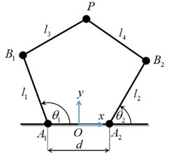
The schematic diagram of the 5R parallel leg considered in this paper is shown in Fig. 2. Links 1 and 2 of lengths and are the proximal links, and links 3 and 4 of lengths and are the distal links. From the reference coordinate frame with origin at , revolute joints of the actuated links 1 and 2 are at a distance of on either side along -axis. Fig. 1 shows the trajectory of the point .
Fig. 1Path trajectory
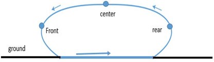
Fig. 2Schematics of the 5R parallel leg structure
2.1. Velocity kinematics
For obtaining velocity kinematics relationship, consider the distances and written in terms of , , and as:
Differentiating Eqs. (1) and (2), we get:
where is , is , and the matrices and can be written in compact form as:
where , , , and are respectively the directed line segments , , , and .
2.2. Inverse position kinematics
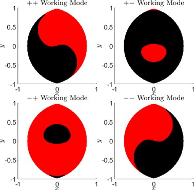
Inverse position kinematics consists of determining the joint angles and given the end-effector position . For every end-effector position within the reachable workspace of the 5R parallel robot manipulator, there are, in general, four solutions. These four solutions are categorized based on whether links 1 and 3 or links 2 and 4 make included angles less than or greater than measured from proximal links 1 or 2. For instance, in Fig. 2, the odd numbered links 1 and 3 make an angle less than (considered '-') and the even numbered links 2 and 4 make an angle greater than (considered '+'). This can be easily determined by checking the signs of and . Using this convention, the four solutions, which are also called working modes, are described as ++, + -, -+, and --. Again, for each of these working modes there exists two assembly modes which divide the workspace of that particular working mode. Movement in the workspace from one assembly mode to another requires disassembly of joint at the end-effector.
For , the workspace is maximum without holes in it as shown in Fig. 3.
Fig. 3Working modes and assembly modes
3. Torque requirement
The relationship between joint torques at and , and the force applied at the end-effector on external surface is given by:
where and and the Jacobian matrix:
It is clear that both and should be full rank to uniquely solve for joint torques, given the force required at the end-effector. We assume that the manipulator does not pass through singularities during normal usage and hence full rank Jacobian is ensured.
The following assumptions are considered as requirements or objectives of the leg structure:
1) End-effector path of the stance leg is a straight line parallel to the body of the quadruped robot during forward motion of the robot while maintaining a constant height.
2) End-effector path of the swing leg is a curve designed to lift the end-effector off the ground and take it to the next foot-hold on the ground. In addition to just lifting off the ground, the path should also circumvent any obstacles present.
3) End-effector can be placed on the ground at any desired foot hold within the limitations of the workspace of the parallel leg structure.
These objectives have to be met with least amount of torque from the actuators.
For constant height motion in trot gait, the vertical ground reaction force is equal to half of the total weight. For a friction coefficient of , the maximum horizontal force will be times the vertical force. Let the Jacobian matrix be written as:
where are elements of the Jacobian matrix dependent on , , , and .
In the configuration shown in Fig. 2, with the coordinate frame’s -axis pointing upwards, the force that the leg mechanism has to generate is negative (). The horizontal force can be either positive or negative depending upon acceleration or decceleration of the robot body. Then Eq. (5) can be written as:
Since we are interested in the magnitude of torques:
We can see from Eqs. (10) and (11) that the vertical force is just a scaling factor for the joint actuator torques. The coefficients of in Eqs. (10) and (11) depend on kinematics alone, i.e., end-effector position trajectory.
Now the problem of joint torque minimization can be stated as follows: For the given height of the robot body (or location where joint actuator is present) from the ground level and the given step length, find the dimensions , , , , and such that the peak absolute values of joint actuator torques and are minimum.
4. Results
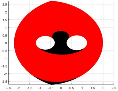
The minimization problem is solved used genetic algorithm. We are optimizing the peak torques of two actuators of this two degree of freedom mechanism to get optimal link lengths. Fig. 4 shows the workspace of the parallel mechanism. The link lengths obtained are 1.1257 m, 1.2306 m, 1.5887 m, 1.7296 m and 1.4937 m. The torque for the path is obtained as 0.264 Nm.
In this paper, we assumed the path is symmetric as shown in Fig. 1 and solving the -+ mode we get the workspace depicted in Fig. 4. There are two types of singularities that can occur while working with parallel mechanism, they are Type I and Type II. In Type I singularity the mechanism loses one degree of freedom, i.e., if one link will follow the motion specified for other link and give some undesirable result. The other type of singularity is Type II, in this case the mechanism will attain some configuration and the actuator will not resist a force applied to end-effector, the actuator should have infinite stiffness which is not possible in practice and thus the end-effector cannot resist any force applied.
The path obtained does not have any Type I singularities.
Fig. 4Workspace obtained after optimization
5. Conclusions
In this paper we found out the optimized link length for the parallel manipulator. The criteria were set as to get maximum horizontal straight path but at minimum expense of torque. Here we have assumed that the path is symmetric (Fig. 1). In next case we would like to formulate asymmetric case and find out the optimized path. In the present study we have considered only the “–+” mode which seemed more promising, in future we want to analyse the remaining modes and study which one would yield the best result that can be incorporated for quadruped gait.
References
-
Campos L., Bourbonnais F., Bonev I. A., Bigras P. Development of a five-bar parallel robot with large workspace. ASME International Design Engineering Technical Conferences and Computers and Information in Engineering Conference, 2011.
-
Briot S., Bonev I. A. Are parallel robots more accurate than serial robots? Transactions of the Canadian Society for Mechanical Engineering, Vol. 31, 2007, p. 445-455.
-
Alıcı G. Determination of singularity contours for five-bar planar parallel manipulators. Robotica, Vol. 18, 2000, p. 569-575.
-
Zhaocai D., Yueqing Y., Xuping Z. Dynamic modeling of flexible-links planar parallel robots. Frontiers of Mechanical Engineering in China, Vol. 3, 2008, p. 232-237.
-
Huang M. Z. Design of a planar parallel robot for optimal workspace and dexterity. International Journal of Advanced Robotic Systems, Vol. 8, 2011, p. 49-56.
-
Gao F., Qi C., Sun Q., Chen X., Tian X., A quadruped robot with parallel mechanism legs. IEEE International Conference on Robotics and Automation (ICRA), 2014.
-
Cui G., Zhang Y. Kinetostatic modeling and analysis of a new 3-DOF parallel manipulator. International Conference on Computational Intelligence and Software Engineering, 2009.
-
Liu X. J., Wang J., Pritschow G. Performance atlases and optimum design of planar 5R symmetrical parallel mechanisms. Mechanism and Machine Theory, Vol. 41, 2006, p. 119-144.
-
Macho E., Altuzarra O., Pinto C., Hernandez A. Workspaces associated to assembly modes of the 5R planar parallel manipulator. Robotica, Vol. 26, 2008, p. 395-403.
-
Hesselbach J., Helm M. B., Soetebier S. Connecting Assembly Modes for Workspace Enlargement. Advances in Robot Kinematics, Springer, 2002, p. 347-356.
-
Figielski A., Bonev I. A., Bigras P. Towards development of a 2-DOF planar parallel robot with optimal workspace use. IEEE International Conference on Systems, Man and Cybernetics, 2007.
-
Dash A. K., Chen I. M., Yeo S. H., Yang G. Workspace generation and planning singularity-free path for parallel manipulators. Mechanism and Machine Theory, Vol. 40, 2005, p. 776-805.
-
Basu D., Ghosal A. Singularity analysis of platform-type multi-loop spatial mechanisms. Mechanism and Machine Theory, Vol. 32, 1997, p. 375-389.
-
Long G. L., Paul R. P. Singularity avoidance and the control of an eight-revolute-joint manipulator. The International Journal of Robotics Research, Vol. 11, 1992, p. 503-515.
-
Lai Z. C., Yang D. C. H. A new method for the singularity analysis of simple six-link manipulators. The International Journal of Robotics Research, Vol. 5, 1996, p. 66-74.
-
Gosselin C., Angeles J. Singularity analysis of closed-loop kinematic chains. IEEE Transactions on Robotics and Automation, Vol. 6, 1990, p. 281-290.
-
Daniali H. M., Zsombor-Murray P. J., Angeles J. Singularity analysis of planar parallel manipulators. Mechanism and Machine Theory, Vol. 30, 1995, p. 665-678.
-
Collins C. L., Long G. L. The singularity analysis of an in-parallel hand controller for force-reflected teleoperation. IEEE Transactions on Robotics and Automation, Vol. 11, 1995, p. 661-669.
-
Bourbonnais F., Bigras P., Bonev I. A. Minimum-time trajectory planning and control of a pick-and-place five-bar parallel robot. IEEE/ASME Transactions on Mechatronics, Vol. 20, 2014, p. 740-749.
-
Wang S. L., Waldron K. J. A Study of the Singular Configurations of Serial Manipulators. Journal of Mechanical Design, Vol. 109, 1987, p. 14-20.
-
Sen S., Dasgupta B., Mallik A. K. Variational approach for singularity-free path-planning of parallel manipulators. Mechanism and Machine Theory, Vol. 38, 2003, p. 1165-1183.
-
Sefrioui J., Gosselin C. M. On the quadratic nature of the singularity curves of planar three-degree-of-freedom parallel manipulators. Mechanism and Machine Theory, Vol. 30, 1995, p. 533-551.
-
Özdemir M. High-order singularities of 5R planar parallel robots. Robotica, Vol. 37, 2019, p. 233-245.
About this article

