Abstract
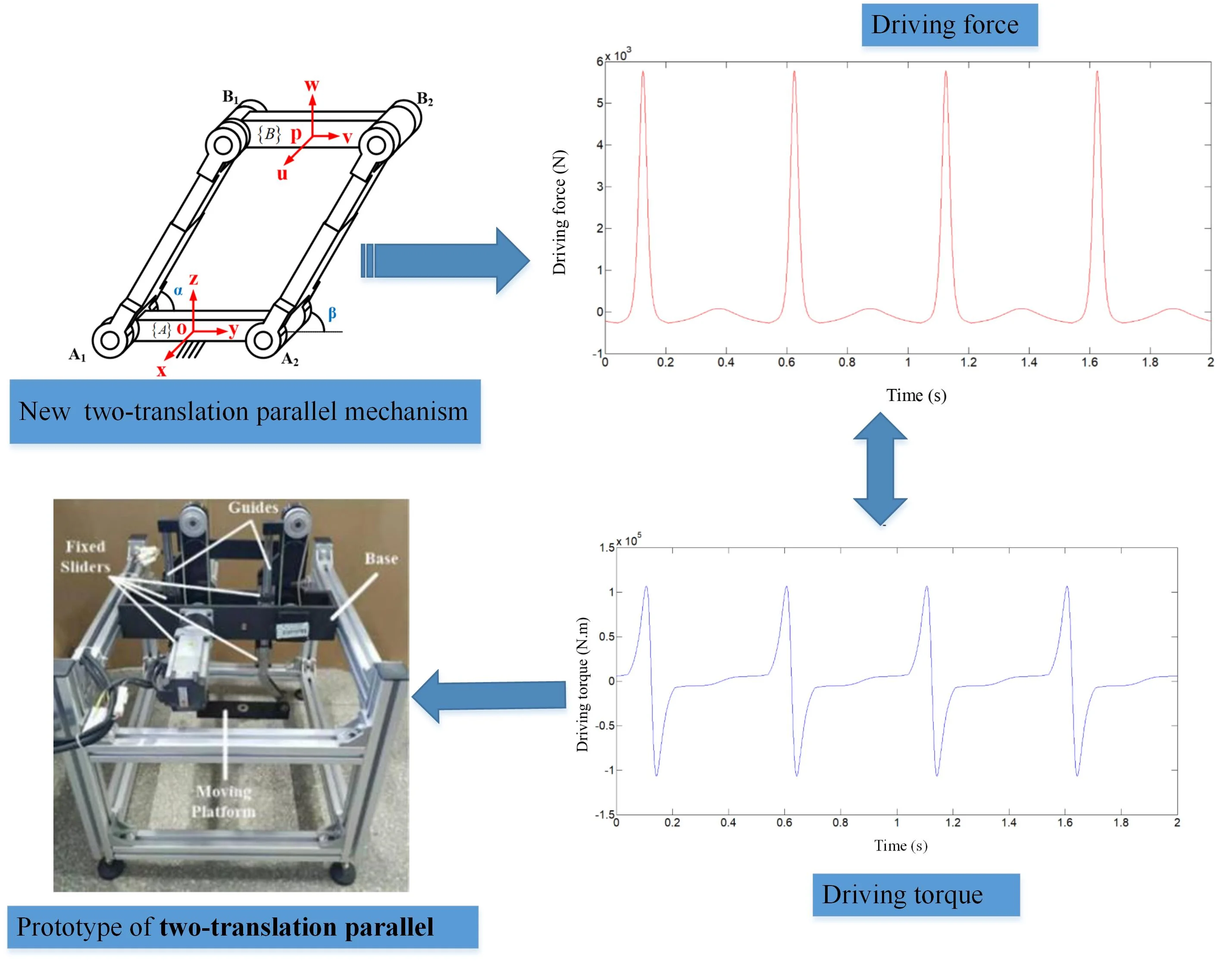
In this paper, we take a novel two-translation parallel mechanism based on variable length parallelogram structure as the research object, and carry out the research on the dynamic characteristics of the mechanism. Based on the principle of virtual work, the dynamic model of the new two-translation parallel mechanism is established. By numerically solving the dynamic model, the dynamic behavior of the new mechanism with impact characteristics is found, which provides a theoretical basis for optimizing this new mechanism.
Highlights
- A dynamic model of the new two-translation parallel mechanism is established.
- Dynamic behavior of the new two-translation parallel mechanism with impact characteristics is revealed.
- A prototype of the new mechanism was manufactured based on the dynamic characteristics.
1. Introduction
In industry, in order to complete the handling and picking and placing of workpieces, only two translational degrees of freedom are required to meet the work requirements [1-3]. Liu proposed a planar two-degree-of-freedom parallel mechanism with a constant direction [1], in which each branch chain contains a planar four-bar mechanism. Kim also proposed a new type of two-translation parallel mechanism composed of two groups of PPa structures (P: moving pair, Pa: parallelogram closed-loop sub-chain) [2]. Professor Huang Tian of Tianjin University used the properties of the parallelogram structure to propose a fully articulated parallel mechanism called Diamond with two translational degrees of freedom. It is a two-dimensional form of the Delta mechanism. The overall performance of the robot is almost comparable to that of Delta. The mechanism is comparable to the single-axis feed mechanism and can be connected in series to form a hybrid mechanism with three translational degrees of freedom [4]. However, the two translational parallel mechanism proposed above needs to connect the two branches in a symmetrical embracing manner, so it has the disadvantages of a large lateral area and small vertical movement space. Based on this, this paper proposes a new two-translation parallel mechanism based on a variable-length parallelogram structure, as shown in Fig. 1(a), and takes the new structure as the research object to carry out the dynamic analysis of the mechanism, and then demonstrate the feasibility of the mechanism.
2. Dynamic modeling of novel two-translation parallel mechanism
Since the robot system is a non-linear and complex dynamic system, its dynamic characteristics must be analyzed in the robot dynamic real-time control system. Rigid body dynamics analysis is mainly to carry out inverse dynamics analysis of rigid body, that is, given the geometric and inertial parameters and motion laws of the mechanical system, the driving force (torque) required to realize this kind of motion is solved. For this reason, this section mainly uses the principle of virtual work to construct the inverse dynamics model of the new two-translation parallel mechanism.
Fig. 1Schematic diagram of kinetic analysis of novel two-translation parallel mechanism
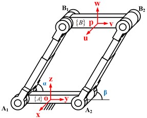
a) The overall schematic diagram
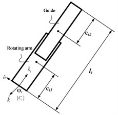
b) Schematic diagram of branch chain
In order to facilitate analysis, as shown in Fig. 1, a coordinate system - is established at the center of the fixed platform , which is marked as , where the axis is parallel to and the axis is parallel to the axis of the rotating pair , and the axis is determined by the right-hand rule. The coordinate system - established on the moving platform is recorded as , where the axis is parallel to , the axis and the rotating pair are in the same direction, and the axis follows the right-hand rule.
First, suppose the external inertial generalized forces acting on the moving platform and each branch chain are and . Since each branch chain in the new two-translation parallel mechanism is composed of sliders and rails, the external inertial force acting on the branch chain can be divided into two parts , where the subscript represents the variables related to the sliders, and the subscript represents variables related to retractable rails. Then the Jacobian matrix of the branch is determined. Finally, the driving force is considered, therefore, the principle of virtual work applied to the new two-translation parallel mechanism can be expressed as:
As shown in Fig. 1, , , which is the rate of change of the input joint, , which represents the speed of the output point of the moving platform. Therefore, the closed loop equation of each branch can be written as:
Derive Eqs. (2) with respect to time, the outcome is:
Because , , , there is:
where is the unit direction vector of the branch chain , and is the unit vector of the direction of the axis of the rotating pair. In order to eliminate , both sides of Eq. (3) are multiplied by at the same time to obtain the following branch chain linear velocity expression:
In order to eliminate , the two sides of Eq. (3) are cross-multiplied by at the same time to obtain the angular velocity of the branch chain:
So we can write .
Derive Eq. (3) with respect to time, the outcome is:
In order to eliminate to obtain the expression of , both sides of Eq. (7) are multiplied by at the same time, the outcome is:
In order to eliminate to obtain the expression of , both sides of the Eq. (7) are cross-multiplied by at the same time, and after finishing, Eq. (8) can be expressed as:
Since the branch chain can be decomposed into two independent parts, the slider and the guide rail, their masses are represented by and respectively, as shown in Fig. 1(b). The position vectors of the two centroids can be determined by the following formula:
After deriving the above two formulas, the linear velocity expressions at the centroids of the two parts of the branch chain are obtained:
Derive Eq. (12) and Eq. (13), we can get the expression of linear acceleration velocity at the centroid of each branch:
Since the end moving platform only has the degree of freedom to move along the axis and the axis, the external inertial torsion force acting on the moving platform can be expressed as:
where is the mass of the moving platform, and are the perturbation torsion force acting on the moving platform along the axis and the axis. and are the gravity along the axis and the axis respectively.
External inertial torsion force acting on the branch chain is:
Among them, . and are the masses of the slider and the guide rail respectively. represents the inertia matrix of the slider whose coordinate origin is on the point and parallel to . And also represents the inertia matrix of the guide rail whose coordinate origin is on the point and parallel to . Because the coordinate system of the point and the point is moving relative to the coordinate system fixed on the fixed platform, the inertia matrix can be obtained by the following transformation:
It is assumed here that the branches are completely symmetric, and are also diagonal matrixs.
From the linear velocity and angular velocity of the slider and the guide rail, the Jacobian matrix and of the branch chain can be obtained:
Among them, , . In the same coordinate system , the Jacobian matrix and of the branch can be derived.
Since the speed and acceleration of the branch chain 1 and the branch chain 2 in the two-translation parallel mechanism are the same, the dynamic equation can be derived after the result obtained by the above calculation is put into Eq. (1), and finally the driving force and driving torque of the two-translation parallel mechanism can be obtained.
3. Dynamic simulation of a novel two-translation parallel mechanism
The structural parameters of the novel two-translation parallel mechanism are shown in Table 1.
Table 1Structural parameters of the novel two-translation parallel mechanism
The mass of the moving platform (kg) | The mass of the slider (kg) | The mass of the rail (kg) | The distance of the slider centroid and the hinge point of fixed platform (mm) | The distance of the rail centroid and the hinge point of moving platform (mm) |
0.947 | 2.042 | 1.059 | 59.700 | 77.520 |
The inertia matrix in the novel two-translation parallel mechanism (kg⋅mm2):
Assume that the motion law of the moving platform of the novel two-translation parallel mechanism is:
Fig. 2Driving force and driving torque
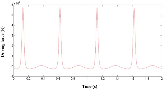
a) Driving force
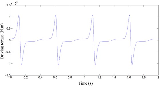
b) Driving torque
Fig. 3The prototype of 2T parallel mechanism
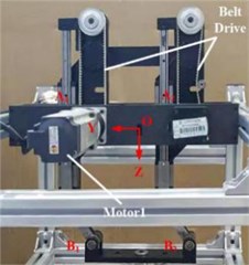
a) Frontal partial view
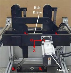
b) Back partial view
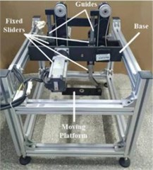
c) Overall view
In addition, the velocity and acceleration of the moving platform can be obtained by calculating the first derivative and the second derivative of the time with the trajectory function. By writing the above dynamic model into MATLAB, the input force and input torque curves of the driver can be obtained, respectively as shown in Fig. 2(a) and 2(b). It can be seen that under this trajectory, an impact will occur in the movement of the novel two-translation parallel mechanism, which will affect the normal operation of the mechanism. For this reason, the structure and motion trajectory of the mechanism need to be further optimized to improve the dynamic characteristics of the mechanism. The prototype of the optimized novel two-translation parallel mechanism is shown in Fig. 3.
4. Conclusions
In this work, a new type of two translational parallel mechanism based on variable length parallelogram structure is taken as the research object, and the dynamic model of the new mechanism is established by using the principle of virtual work. Through numerical solution, the dynamic characteristics such as driving force and driving torque of the new two translational parallel mechanism are obtained, which lays the foundation for optimizing the structure of the mechanism. Based on the dynamic characteristics, a prototype of a new mechanism was manufactured.
References
-
Liu X. J., Wang Q. M., Wang J. Kinematics, dynamics and dimensional synthesis of a novel 2-DoF translational manipulator. Journal of Intelligent and Robotic Systems, Vol. 41, Issue 4, 2005, p. 205-224.
-
Pham V. B. N., Kim H. S. Dynamics analysis of a 2-DOF planar translational parallel manipulator. Journal of the Korean Society for Production and Manufacturing Systems, Vol. 22, Issue 2, 2013, p. 185-191.
-
Yang Y., Peng Y., Pu H., et al. Design of 2-degrees-of-freedom (DOF) planar translational mechanisms with parallel linear motion elements for an automatic docking device. Mechanism and Machine Theory, Vol. 121, 2018, p. 398-424.
-
Huang T., Liu S., Mei J., et al. Optimal design of a 2-DOF pick-and-place parallel robot using dynamic performance indices and angular constraints. Mechanism and Machine Theory, Vol. 70, Issue 6, 2013, p. 246-253.
About this article

This paper was supported by the following research projects: by the Special Project of Ningde Normal University in 2018 (Grant No. 2018ZX401, Grant No. 2019ZX401, Grant No. 2018Q102) and Research project for Yong, Middle-aged Teacher in Fujian Province (Grant No. JT180597). These supports are gratefully acknowledged.
