Abstract
Dynamic behavior of reciprocating compressor system, with translational clearance between the crosshead and guide under time-varying cylinder load, is investigated. In order to analyze the dynamic response of the system with translational clearance, a novel nonlinear dynamic model is established based on the Lagrangian approach. The numerical solution of the dynamic equation is calculated by the Runge-Kutta method. The results show that the translational clearance has a great effect on the reciprocating compressor, and the more the translational clearance, the great the influence. Moreover, the phase space of the crosshead reveals that the reciprocating compressor system with translational clearance has chaotic characteristics.
1. Introduction
Reciprocating compressors are one of the most popular machines used in petroleum and chemical production processes, such as gas compression, petroleum transportation and natural gas transportation [1, 2]. In practice, with reciprocating compressor working on a period of time, as the result of manufacture tolerance and wear, some translational clearances in its joints commonly exist, and they are inevitable. In the case of oversized joint clearances, contact forces generate impulsive effect, and this situation causes increased vibration and noise, and reduce system reliability, stability, life and precision. So, clearances play a significant role in the prediction of kinematic and dynamic behavior of reciprocating compressor [3].
In the last decade, the fault diagnosis researches of reciprocating compressor are focused on vibration signal extraction. On the valve failure, Wang et al. [4] presented an experimental study of the fault diagnosis of reciprocating compressor valves with acoustic emission technology and simulated valve motion. In their study, the results indicate that an earlier occurrence of the suction process can diagnose suction valve leakage and that an earlier occurrence of the discharge process can be used for detecting discharge valve leakage. In addition, some meaningful research results have been made, such as the characteristics extraction of the piston rod [5], the characteristic extraction of the impact signal at the reverse angle [6], and so on. However, few scholars have studied the failure mechanism of reciprocating compressor with translational and revolute clearances fault. Zhao et al. [7] performed a parameter optimization approach for planar joint clearance model and its application for dynamics simulation of reciprocating compressor. The dynamics response experimental test verified the effectiveness of this application. Jiang et al. [8] focused on the study of the dynamic response and diagnosis method on wear fault of small-end bush of a connecting rod based on the dynamic simulation and vibration signal analysis.
Because the single cylinder reciprocating compressor is a crank slider mechanism shown in Fig. 1, the dynamics analysis of the crank slider mechanism with translational clearance can be used for reference. Flores et al. [9, 10] developed a methodology for a dynamic modeling and analysis of rigid multibody systems with translational clearance joints based on the non-smooth dynamics approach. Zhuang and Wang [11] carried out a modeling and simulation method for the rigid multibody system with frictional translational joints between a slider and guide.
In this work, based on the previous research results, we carry out the dynamic analysis of the reciprocating compressor with translational clearance fault under time-varying cylinder load. The paper is organized as follows: The dynamic model of single cylinder reciprocating compressor with translational clearance fault is established in Section 2. The influence of translational clearance size is discussed in Section 3. Furthermore, the conclusions of this paper are given in Section 4.
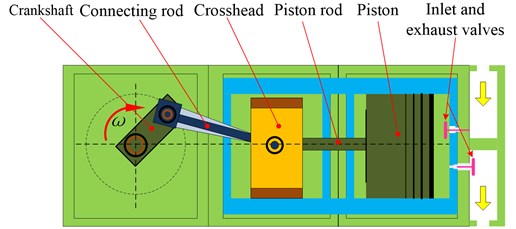
Fig. 1Schematic diagrams of single cylinder reciprocating compressor
2. Dynamic model of single cylinder reciprocating compressor with translational clearance
2.1. Model of time-varying cylinder load
The crankshaft of single cylinder reciprocating compressor rotates a circle, driving the connecting rod, the crosshead and the piston to reciprocate. The cylinder can realize the four processes of expansion, suction, compression and exhaust. In a circle, As the crankshaft turns clockwise, the crosshead and piston move from right to left, working volume that is located at the right side of the piston gradually increases, cavity gas gradually expands, and cylinder pressure gradually decreases, which is expansion process. When the cylinder internal pressure decreases to slightly less than the external pressure of the cavity, the inlet valve is opened, until the crosshead and piston move to the far left, which is suction process. In the suction process, cylinder pressure is almost constant. The suction process is accomplished at the far left. The compression and exhaust processes are mostly the opposite of expansion and suction. It is obvious that the cylinder pressure can be seen as a time-varying load. Since the change of cylinder pressure is periodic, it is more appropriate to use the crankshaft rotation angle as the variable for the cylinder pressure expression. Pressure expression can be expressed as follow:
where is the cylinder pressure, denotes cylinder pressure coefficient, is given by:
where denotes the crankshaft rotation angle in a clockwise direction, is the number of cycles of crankshaft rotation.
2.2. Contact model with translational clearance
The translational joint is obtained through an infinitely enlarged translational joint radius. Therefore, the contact model with translational clearance can refer to the revolute clearance. When the translational clearance shown in Fig. 2 is too large, impact will take place between the crosshead and guide when the following condition is met at about the relative penetration depth of . The relative penetration depth of can be defined by:
in which denotes the relative penetration depth, is the centroid coordinates of the crosshead in the y direction, represents translational clearance size.
Assuming that the rotation of the crosshead can be ignored during the collision, namely, the crosshead is only perpendicular to the slide when the collision appears. According to Lankarani-Nikravesh contact force model and Ambrósio friction model, the contact force can be written as:
where is the dynamic friction coefficient; is the relative tangential velocity along the direction of the guide; is a dynamic correction coefficient; is the nonlinear power exponent, which is generally set to 1.5 for metallic surfaces; denotes the restitution coefficient; is the relative penetration velocity; is the initial impact velocity of the impact point, which should be updated for each impact process; is the stiffness coefficient; represent direction of the force ; and are computed by the following equation:
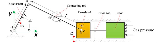
Fig. 2Schematic of single cylinder reciprocating compressor
2.3. Model of dynamics
Distinctly, there are two degrees of freedom for reciprocating compressor systems with translational clearance. So, two generalized coordinates can be represented by and . As can be seen from Fig. 2, the velocity of crankshaft, connecting rod and crosshead can be obtained as follow, respectively:
where and (1, 2, 3) are the velocity of crankshaft, connecting rod and crosshead, respectively; and are the angle of the crankshaft and connecting rod with the -axis, respectively. and represent the length of crankshaft and connecting rod, respectively.
According to Eqs. (6)-(8), the kinetic energy and potential energy of crankshaft, connecting rod and crosshead can be calculated as follows:
where, , and are the kinetic energy of crankshaft, connecting rod and crosshead, respectively. is the sum of potential energy for the reciprocating compressor system. , and are the mass of crankshaft, connecting rod and crosshead, respectively.
Substitute Eqs. (1), (4) and (10) into following Lagrange motion equation Eq. (11), the dynamic equation can be obtained:
where and are the kinetic and potential energies of the reciprocating compressor system, respectively. is the nonconservative generalized force corresponding to the generalized coordinate. The expression of and are given as:
where denotes the resultant of external force acting at the center of mass. represents the external torque acting on body . and denote the translational and rotational velocity for the mass center of body , respectively.
3. Results and discussion
In this section, we discuss the dynamic behavior of reciprocating compressor with translational clearance between the crosshead and guide. Solving Eq. (11) by Runge-Kutta Method, the numerical solution of and can be obtained. Subsequently, the corresponding numerical solution of displacement, velocity and acceleration of the crosshead can be calculated. In the numerical solution, 2D12 reciprocating compressor is used for the research object, and its structural parameters are as follows: 0.12 m, 0.6 m, 1 kg, 5 kg, 1 kg, 0.5, 0.9, 2×10⁵, 2.399×10¹⁰. Figs. 3 to 5 display the dynamic response results of reciprocating compress with different translational clearance in y direction under time-varying cylinder load.
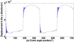
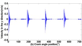
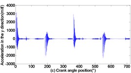
As can be seen from Figs. 3 to 5, with the increase of translational clearance, the influences of the crosshead increase in direction. It is noteworthy that the variational clearance does not influence the crosshead displacement in a conspicuous way. When the clearance sizes increase from 0.1 mm, 0.2 mm to 0.3 mm, the corresponding maximal deviation value of the displacement increases from the 0.1519 mm, 0.1522 mm to 0.1523 mm at the low dead point, and the maximal deviation value of velocity increases from 0.0056 m/s, 0.1493 m/s to 0.2297 m/s. In sharp contrast, the crosshead acceleration is distinctly influenced and the maximal peak value of crosshead acceleration increases from 1455 m/s2, 2351 m/s2 to 3190 m/s2. Obviously, the more the translational clearance size, the great the influence of displacement, velocity and acceleration of the crosshead. The influence of acceleration is larger than the displacement and velocity.
Fig. 3Dynamic response of reciprocating compress with translational clearance 0.1 mm in y direction: a) displacement response; b) velocity response; c) acceleration response; d) phase space trajectory
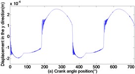
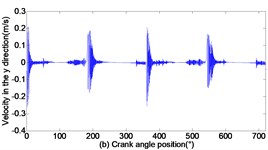
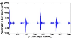
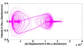
Fig. 4Dynamic response of reciprocating compress with translational clearance 0.2 mm in y direction: a) displacement response; b) velocity response; c) acceleration response; d) phase space trajectory
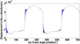
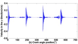
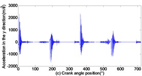
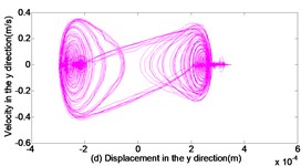
Fig. 5Dynamic response of reciprocating compress with translational clearance 0.3 mm in y direction: a) displacement response; b) velocity response; c) acceleration response; d) phase space trajectory
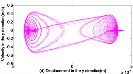
In addition, Fig. 3(d), Fig. 4(d) and Fig. 5(d) depict the phase trajectories of displacement and velocity. one can observe that the strange attractors are shown in Fig. 3(d), Fig. 4(d) and Fig. 5(d). That is to say, the reciprocating compressor system indicates chaotic behavior.
4. Conclusions
In this interesting work, the dynamic behavior of reciprocating compressor for single cylinders is studied with translational clearance. The nonlinear dynamical equation is established under the time-varying cylinder load, and the numerical solution of the equation is obtained by MATLAB software. By analyzing the dynamic response of the reciprocating compressor system with translational clearance, some dynamic behaviors are obtained as follows:
1) With the increase of translational clearance, the influence of displacement, velocity and acceleration of the crosshead increase in direction, where the influence of displacement, velocity and acceleration gradually increases.
2) The reciprocating compressor system with translational clearance can be observed strange attractors. the result reveals that this system is characterized by chaotic behavior with translational clearance.
References
-
Elhaj M., Gub F., Ballb A. D. Numerical simulation and experimental study of a two-stage reciprocating compressor for condition monitoring. Mechanical Systems and Signal Processing, Vol. 22, 2008, p. 374-389.
-
Almasi A. A new study and model for the mechanism of process reciprocating compressors and pumps. Proceedings of the Institution of Mechanical Engineers, Part E: Journal of Process Mechanical Engineering, Vol. 224, 2010, p. 143-148.
-
Dupac M., Beale D. G. Dynamic analysis of a flexible linkage mechanism with cracks and clearance. Mechanism and Machine Theory, Vol. 45, 2010, p. 1909-1923.
-
Wang Y. F., Gao A., Zheng S. L. Experimental investigation of the fault diagnosis of typical faults in reciprocating compressor valves. Proceedings of The Institution of Mechanical Engineers Part C-Journal of Mechanical Engineering Science, Vol. 230, Issue 13, 2016, p. 2285-2299.
-
Ma J., Jiang Z. N., Gao J. J. A reciprocating compressor fault diagnosis method based on piston rod axis orbit. Journal of Vibration Engineering, Vol. 25, Issue 4, 2012, p. 453-459, (in Chinese).
-
Du X. Y., Jiang Z. N. Fault diagnosis of the small end bushing of connecting rod of reciprocating compressor based on angular domain. Compressor Technology, Vol. 5, 2012, p. 62-64, (in Chinese).
-
Zhao H. Y., Xu M. Q., Wang J. D. A parameters optimization method for planar joint clearance model and its application for dynamic s simulation of reciprocating compressor. Journal of Sound and Vibration, Vol. 344, 2015, p. 416-433.
-
Jiang Z. N., Mao Z. W., Zhang Y. D. A study on dynamic response and diagnosis method of the wear on connecting rod bush. Journal of Failure Analysis and Prevention, Vol. 17, Issue 4, 2017, p. 812-822.
-
Flores P., Ambrósio J., Claro J.C., Lankarani H. M. Translational joints with clearance in rigid multibody systems. Journal of Computational and Nonlinear Dynamics of ASME, Vol. 3, Issue 1, 2008, p. 110071.
-
Flores P., Leine R., Glocker C. Modeling and analysis of planar rigid multibody systems with translational clearance joints based on the non-smooth dynamics approach. Multibody System Dynamics, Vol. 23, Issue 2, 2009, p. 165-190.
-
Zhuang F. F., Qi W. Modeling and simulation of the non-smooth planar rigid multibody systems with frictional translational joints. Multibody System Dynamics, Vol. 29, 2013, p. 403-423.
About this article

This paper was supported by the following research projects: “Fujian Natural Science Foundation” (Grant #2015J01643), “Ningde City Science and Technology Project” (Grant #20150034), “Education Science Project of Young and Middle-aged Teachers of Universities in Fujian Province” (Grant #JZ160396 and Grant #JAT160527).
