Abstract
The clearance faults on joint of moving mechanism are most common in a reciprocating compressor. In order to investigate the relationship between the clearance faults and the dynamic behavior of the moving mechanism, a dynamic model with clearances of a reciprocating compressor is built via software ADAMS. We take into the clearance size and clearance number into consideration and set clearance fault on the joint between the crank and connecting rod, the joint between connecting rod and crosshead and both joints of connecting rod, exploring the effect of these factor on the dynamic response. Then we make a non-linear analysis to estimate the chaos behavior. In the end, we conclude that the clearance size and the number of clearance both strongly influence the dynamic behaviors of the moving mechanism, so do the position where clearance fault happens. As the clearance size increases or the number of clearance fault increase, the acceleration will oscillate more violent and have higher amplitude, furthermore, it is more possible to show chaotic behaviors.
1. Introduction
Reciprocating compressors are widely used in the industrial field such as natural gas transportation and storage, petrochemical, chemical, and refrigeration industries, and have pivotal industrial states. The fault detecting and diagnosing technology for the reciprocating compressor has always been a hot topic for researches [1]. Especially for failures of the moving mechanism, which are core components in a reciprocating compressor, it may cause serious accidents, and is difficult to monitor and diagnose. Clearance faults on the joint are the most common faults in the moving mechanism a reciprocating compressor, due to wear and assembly error. In previous, scholars like Flores [2, 3] and Mohamed [4] have made a great deal of achievements in the joints with clearance for multi-body systems. Zhao [5] presented a parameters optimization method for joints clearance model and applied it to the simulation of the reciprocating compressor. Cheng [6] analyze the dynamic response of a reciprocating compressor with a revolute clearance joint. However, so far, there are no efficient methods for diagnosing these failures. The reason can be attributed to two aspects. For one hand, the reciprocating compressors, a symbol for reciprocating machines, have complicated structure, several various forms of motions and working load, poor working conditions, and abundant motivating source. As a result, that the faults have strongly non-linear and complex signals, and couldn’t be easily monitored and identified. On the other hand, the moving mechanism is inside the hermetic chamber, which causes that there are few effective approaches to extract the fault information [7]. Therefore, it is necessary to investigate the dynamic behaviors of the mechanism under faults for revealing the fault mechanism.
This paper aims at the clearance faults on the joints of the moving mechanism, investigating the dynamic behaviors of the moving mechanism under clearance fault and exploring the relationship between these behaviors and the clearance faults. We take the clearance size and the number of clearance into consideration and establish a dynamic model of the moving mechanism with clearance by the software ADAMS. Through dynamic analysis and non-linear analysis of the model, we try to find out the effect of the clearance faults on the dynamic behavior of the mechanism and to reveal the fault mechanism.
2. The model of the reciprocating compressor
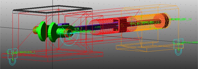
In this paper, a single-stage single-acting reciprocating compressor is taken as investigating object. We establish its simplified model with clearance joints in commercial software ADAMS, as shown in Fig. 1. The model is mainly composed of the body, crank, connecting rod, crosshead, piston assembly and cylinder. Table 1 provides the major characteristics of the model.
Table 1Major characteristics of the reciprocating model
Simulation characteristics | Value |
Length of the crankshaft (mm) | 120 |
Length of the connecting rod (mm) | 600 |
Stroke of the piston (mm) | 240 |
Radius of the piston (mm) | 50 |
Pressure in suction process (MPa) | 0.105 |
Pressure in discharge process (MPa) | 0.393 |
Fig. 1The schematic diagram of the reciprocating compressor
2.1. The air force model
The gas force is caused by the pressure gases during the working process, of which the pressure varies periodically and has four various forms in one working cycle. To simplify the calculation, we assume that the compression and expansion process are isentropic, and the pressure gases are ideal gases. The gas force can be calculated by Eq. (1):
where is the cylinder pressure, is the cylinder pressure in the suction process, is cylinder pressure in the discharge process, is the radius of the piston, is the displacement of the piston that can be obtained by the geometric relationship and the motion relationship of the crank mechanism, as shown in the Eq. (2), is the operating stroke of the piston, is the clearance of clearance volume:
where is the crankshaft radius, is the crankshaft angle, is the length of the connecting rod, and is the ratio of the crankshaft radius to the length of the connecting rod.
According to the Eq. (1), we utilize the IF function provided in the ADAMS to simulate the gas force.
2.2. The clearance model
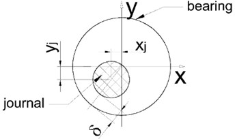
In previous working, the revolute joint with clearance model mainly includes the massless rod model, the two mode model and the three mode model [2, 6]. This paper employed the three mode model, describing the journal inside the bearing that has three modes: free flight mode, contact mode, and impact mode, as shown in Fig. 2.
The contact condition for the revolute joint with clearance can be given by Eq. (3):
where is the radial clearance between journal and bearing, and are the relative displacements. 0 corresponds to impact, 0 represents contact, and 0 means free flight.
Fig. 2The clearance revolute model
2.3. The contact model
For the contact between journal and bearing, we apply the contact method based on the IMPACT function available in ADAMS function library [4]. The contact model treats contact as a non-linear spring-damper, based on the Hertz contact model and on the Coulomb friction model. The contact force is calculated by the penetration and the speed of penetration, as the following Eq. (4) [2-4]:
where is the stiffness coefficient that depends on the material property and the radius, is the penetration, is the deformation force exponent that equals to 1.5 for the metallic contact, is a positive real value of the boundary penetration, is maximum damping coefficient:
where is the Radius, is the Poisson’s ratio, is the modulus of the elasticity.
The Coulomb friction force can be given by Eq. (6) [2-4]:
where is the friction coefficient, is the normal force, is the relative tangential velocity.
3. Dynamic simulation of the model
In order to investigate the relationship between the clearance fault and the dynamic behavior of the moving mechanism, we take different clearance sizes and different numbers of clearance into consideration, exploring the effect of these factors on the dynamic behaviors of moving part. During the simulation, we choose Gear Stiff integrator (GSTIFF) and integral formulation SI2; the speed of the crankshaft is 500 (rpm); the step time is 0.0001 (s); the integration tolerance is 1E-005.
3.1. Simulation for clearance fault on the joint between crank and connecting rod
In this case, we set the revolute joint between the crank and connecting rod with clearance 0.1 mm, 0.2 mm, 0.3 mm, and set the other joints as ideal joints, exploring the effect of different size clearance joint between the crank and connecting rod on the dynamic response of moving mechanism. Fig. 3 shows the dynamic response of the moving mechanism in the case of clearance fault on the joint between the crank and connecting rod.
3.2. Simulation for clearance fault on the joint between connecting rod and crosshead
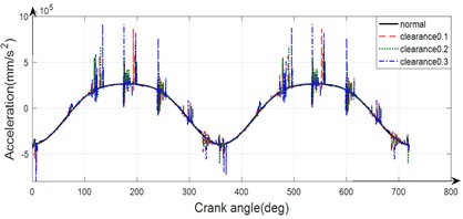
In this case, we set the revolute joint between the connecting rod and crosshead with clearance 0.1 mm, 0.2 mm, 0.3 mm, and set the other joints as ideal joints, investigating the effect of different size clearance joint between connecting rod and crosshead on the dynamic response of moving mechanism. Fig. 4 shows the dynamic response of the moving mechanism in the case of clearance fault on the joint between the connecting rod and crosshead.
Fig. 3The dynamic response of the moving mechanism in the case of clearance joint between crank and connecting rod
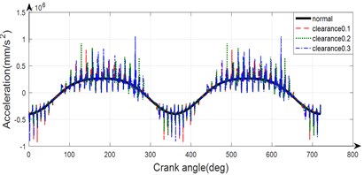
Fig. 4The dynamic response of the moving mechanism in the case of clearance joint between connecting rod and crosshead
3.3. Simulation for clearance fault on both joints of the connecting rod
In the case of clearance faults on both joints of the connecting rod, we set both the revolute joint between connecting rod and crank, and the joint between the connecting rod and crosshead with clearance 0.1 mm, 0.2 mm, 0.3 mm, and set the other joints as ideal joints, to study the dynamic response of the moving mechanism as the number of clearance joints increasing, so do the size of clearance. Fig. 5 shows the dynamic response of the moving mechanism in the case of clearance fault on the both joint of the connecting rod.
Fig. 5The dynamic response of the moving mechanism in the case of clearance joint between connecting rod and crosshead
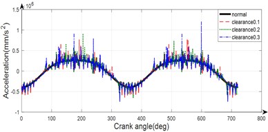
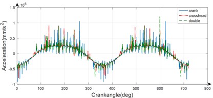
Fig. 6Comparison of the dynamic response of the mechanism in different case
4. Result discussion and non-linear analysis
From Fig. 3-5, we can see that the clearance size strongly affect the acceleration of the mechanism. As the clearance size increase, the acceleration oscillates more intensely and has the higher amplitude.
Fig. 6 shows the comparison of the dynamic response of the mechanism in the above cases. As shown in Fig. 6, the clearance number also strongly influence the dynamic behaviors of the moving mechanism, and the acceleration in the double clearance fault case oscillates more intensely and has a higher amplitude than any of the other case. In addition to that, the position where the clearance faults happen also affects the dynamic behavior of the mechanism.
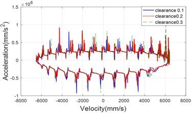
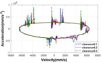
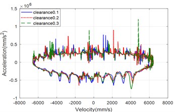
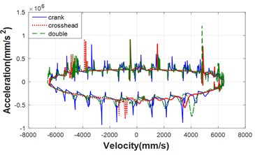
According to the above dynamic analysis for the moving mechanism with clearance, it is not difficult to draw the phase trajectories diagram and discuss the chaotic behavior of the mechanism. Fig. 7, 8 show the phase trajectories of velocity-acceleration diagram for the three cases. As can be seen from the two figure, as the clearance size increases, it is more possible to show the chaos behavior, and the number of the clearance also affects the chaotic behavior of the mechanism.
Fig. 7The phase trajectories of the velocity-acceleration with different clearance size in the three case: a) the case of clearance joint between crank and connecting rod, b) the case of clearance joint between connecting rod and crosshead, c) the case of clearance joint of both connecting
a)
b)
c)
Fig. 8The comparison for phase trajectories of the velocity-acceleration in the different case with clearance 0.3
5. Conclusions
In order to investigate the effect of the clearance faults on the dynamic behavior of the moving mechanism in a reciprocating compressor, a dynamic model for the mechanism with clearance is established via software ADAMS in this paper. We take into the clearance size and clearance number into consideration and set clearance fault on the joint between the crank and connecting rod, the joint between connecting rod and crosshead and both joints of connecting rod. As the simulation result shown, we can conclude that the clearance size strongly influences the dynamic behaviors of the mechanism, the bigger size is, the more violent the acceleration oscillates, and the higher amplitude it has. We also get that the number of the clearance faults and the position the faults happened strongly affect the dynamic response of the mechanism. What’s more, as the clearance size increases, or the numbers of clearance faults increase, it is more possible to displays chaotic behavior.
References
-
Almasi A. A new study and model for the mechanism of process reciprocating compressors and pumps. Proceedings of the Institution of Mechanical Engineers, Part E: Journal of Process Mechanical Engineering, Vol. 224, Issue 2, 2010, p. 143-147.
-
Flores P., Ambrósio J., Claro P. J. Dynamic analysis for planar multibody mechanical systems with lubricated joints. Multibody System Dynamics, Vol. 12, 2004, p. 1-47.
-
Flores P. A parametric study on the dynamic response of planar multibody systems with multiple clearance joints. Nonlinear Dynamics, Vol. 61, 2010, p. 633-653.
-
Ben Abdallah, M. A., Khemili, I., Aifaoui N. Numerical investigation of a flexible slider-crank mechanism with multijoints with clearance. Multibody System Dynamics, Vol. 38, Issue 2, 2016, p. 173-199.
-
Zhao Hai Yang, Xu Min Qiang, Wang Jin Dong, Li Yong Bo A parameters optimization method for planar joint clearance model and its application for dynamics simulation of reciprocating compressor. Journal of Sound and Vibration, Vol. 344, 2015, p. 416-433.
-
Cheng Shouguo, Liu Shulin Dynamics analysis of reciprocating compressor with a clearance between crankshaft and connecting rod. Vibroengineering Procedia, Vol. 15, 2017, p. 38-43.
-
Xiao Shungen, Liu Shulin, Cheng Shouguo, Xue Xiaogang, Song Mengmeng, Sun Xin Dynamic analysis of reciprocating compressor with clearance and subsidence. Journal of Vibroengineering, Vol. 19, Issue 7, 2017, p. 5061-5085.
About this article
This work is supported by the National Natural Science Foundation of China (Grant No. 51575331)
