Abstract
In order to improve the synchronicity of the gripper of automatic drilling rig, three kinds of clamping devices for automatic drilling rig were designed to overcome the problem of deviation between the clamping center of the clamping device and the rotary center of the power head. At the same time, the driving characteristics, structures and working principle of the three grippers were introduced. With the finite element analysis conducted on the main structure parts, the results showed that the structure design and the parameter selection of the synchronous clamping mechanism component could meet the application requirements and could provide the guarantee to the reliability of the clamping mechanism and the integral performances of the automatic drilling rig.
1. Introduction
Clamping device is an important component for automatic drilling machine [1]. At present, there are few researches on gripper of coal mine rig. Due to the large opening and uneven load at both ends of the conventional hydraulic elastic clamps, the telescopic action of the hydraulic cylinders on gripper both sides is out of sync [2]. This not only reduce the clamping accuracy of the clamping device itself, but also affect the coaxiality of the clamping center of the clamping device and the rotary center of the power head. In addition, according to the feedback by field use, the alignment accuracy of clamping device equipped with a shunt collector valve to facilitating the clamping cylinder synchronization is very low, because of the limitation of hydraulic system response time and flow matching of the shunt valve. When the automatic drilling rig is working, the manipulator cooperates with the power head and the gripper to complete the process of loading and unloading the drill pipe. The neutrality of the gripper directly affects the subsequent smooth loading and unloading of the drill pipe. In view of this, it is urgent to develop a new type of gripper to solve the above problems and meet the requirements of automatic drilling system.
2. The driving characteristics of the gripper in three schemes
According to the requirement of clamping precision of automatic drilling machine, three kinds of clamping devices with synchronization device are designed to improve the alignment precision of the conventional clamping device and ensure that the clamping center of the clamping device and the rotary center of the power head are always coaxial.
(1) In scheme 1, synchrodrive of two racks and middle gear meshing is adopted. Under the push of the clamping cylinder on both sides, the left and right slip bowls drive two racks meshing with gear closely to achieve synchronous transmission.
(2) Scheme 2 adopts the synchronous transmission mode of rack and right slip holder meshing with the upper and lower gear shaft. Wear resistant plate is designed under the rack. When rack contacting with wear resistant plate due to deformation, wear resistant plate plays the role of supporting rack as a vulnerable part and also ensures the close meshing of tooth plate, gear shaft and right slip seat.
(3) The synchronous mechanism in scheme 3 is a connecting rod mechanism restricting each other. The clamping cylinders on both sides extend to push the left and right slips to move toward the center. At this time, the left and right slips drive the support plate to move towards each other. The connecting pieces and connecting rods connected by the plates rotate around the stepped shaft to play a synchronous transmission function.
3. Structural principle of gripper
3.1. Conventional gripper structure
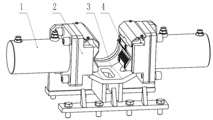
As shown in Fig. 1, conventional grippers are mostly left-right symmetrical structure, consisting of clamping cylinders, a holder body, slips, and slip bowls. When working, driven by the clamping oil cylinders on both sides, the left and right slips holder drives the relative movement of the left and right slips respectively. In the process of automatic drilling, the drill pipe manipulator sends the drill between the power head and the clamper. At this time, the clamper and the drill pipe manipulator are required to accurately cooperate with each other to realize the automatic loading and unloading function of multiple specifications of drill pipe. Therefore, the clamping cylinders on both sides of the clamping device of automatic drilling machine should be synchronized during the clamping process to meet the real-time centering and prevent the drill rod from being clamped off. In order to realize the purpose of fully automated drilling in coal mines, the article designs three grippers with synchronization devices.
Fig. 1Conventional holder (hiding the side plate on one side of the holder body), 1 – clamping cylinder; 2 – slip bowl; 3 – gripper body; 4 – slip
3.2. Gripper solution one
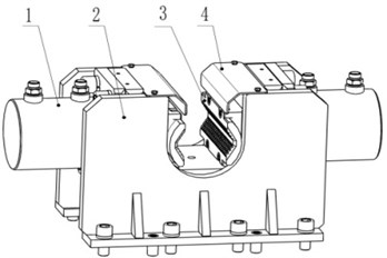
As shown in Fig. 2, the synchronous gripper has a symmetrical structure, which is composed of clamping cylinders, a gripper body, slips, dustproof plates, a gear, a intermediate shaft, a long locating ring, a self-oiling bearing, a short locating ring, racks, slip bowls and other parts. Among them, the clamp body is fixed to the feeder body of the drilling machine through bolt connection. The clamping cylinder is fixed symmetrically on both sides of the clamp body through bolt connection. The end of the piston rod of the clamping cylinder is connected to the slip holder by screws, and the slip holder is fixed with the slip seat by bolts. The two racks are fixed to the left and right slips respectively by bolt connection, and contact surfaces of racks and slips respectively are designed with matching areas to limit their installation positions. The intermediate shaft is a gear shaft, which is connected with the gripper body by bolts through the bottom center hole of the gripper body. Both ends of the gear are positioned respectively by a long limit ring and a short limit ring. A self-oiling bearing is installed between the gear and the intermediate shaft, and the self-oiling bearing is fixed with the intermediate shaft by an interference fit, which is used to provide lubrication and support for the rotation of the gear. When working, under the push of the clamping cylinder on both sides, the left and right slips holders drive two racks meshing with the gear closely to play a synchronous driving role, so as to drive the synchronous movement of the left and right slips to clamping the drill tool. When slips need to be removed, remove the connecting bolts. The contact surface of slip and drill rod is V-shaped plane contact, so within a certain range, drill rods of different specifications can be clamped by the same slip, saving the time of replacing slips.
Fig. 2Gripper solution one: 1 – clamping cylinder; 2 – gripper body; 3 – slip; 4 – dust shield; 5 – gear; 6 – intermediate shaft; 7 – long locating ring; 8 – self-oiling bearing; 9 – short locating ring; 10 – rack; 11 – slip bowl
3.3. Gripper solution two
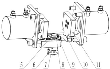
As shown in Fig. 3, the transmission mode of the synchronous gripper is similar to that in Scheme 1, except for the difference in the structure of the synchronous mechanism. The synchronous mechanism in Scheme 2 belongs to the upper and lower meshing transmission of gear and rack. The upper rack is replaced by the bottom of the right slip bowl, the left slip bowl has the same structure as the slip bowl in scheme 1, and the contact surface between the left slip bowl and the rack is also designed with matching surface, which has the function of limiting position during installation. There is a wear plate installed under the rack, and the wear plate is fixed to the holder body by bolts. The wear plate is designed under the tooth plate, and the wear plate is fixed to the holder body by bolts. The wear plate and the rack are not in contact, and there is a small gap between them. When working, clamping cylinders on both sides extend to push the left and right slips toward the center. At this time, the left slip bowl drives the gear plate meshing with the right slip bowl to play a synchronous driving role. Due to the long structure of the rack, there may be a downward deviation phenomenon on the right end meshing surface when meshing with the gear shaft. When the rack is in contact with the wear plate due to deviation, the wear plate, as a vulnerable part, plays the role of supporting the rack. Meanwhile, it also ensures the rack, gear shaft and the right slip bowl are tightly engaged, further improving the synchronicity and centering of the left and right slips when clamping the drill tool.
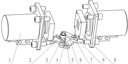
Fig. 3Gripper solution two (hide gripper body): 1 – left slip bowl; 2 – rack; 3 – wear plate; 4 – self-oiling bearing; 5 – gear shaft; 6 – right slip bowl; 7 – clamping cylinder
3.4. Gripper solution three
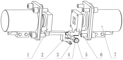
As shown in Fig. 4, the gripper in scheme three uses linkage assembly to achieve synchronous transmission. Two support plates are fixed respectively to the left and right slips by bolts, and contact surfaces of the support plates and slips are designed with fitting surfaces to limit their mounting positions. Stepped shaft, passing through the center hole at the bottom of the holder body, is connected with the gripper body by bolts. Two connecting rods are nested up and down on the stepped shaft, and the step of the stepped shaft plays a role of the connecting rod positioning up and down along the axis. A self-oiling bearing is installed between the stepped shaft and the connecting rod, and it is fixed to the stepped shaft through an interference fit to providing lubrication and support for the rotation of the connecting rod. Similarly, self-oiling bearings are installed at both ends of the connecting rod and the connecting piece, and are connected to the support plate by short pins and long pins. The synchronizing mechanism in scheme three belongs to the link mechanism restricting each other. When working, the clamping cylinders on both side extend to push the left and right slip bowls moving toward the center. At this time, the left and right slip bowls drive the support plate moving toward each other, and connecting plates and connecting rods connected with support plates rotate around the step axis to achieve synchronous driving.
Fig. 4Gripper solution three (hide gripper body): 1 – clamping cylinder; 2 – self-oiling bearing; 3 – step axis; 4 – connecting rod; 5 – short pin; 6 – connecting piece; 7 – long pin; 8 – support plate; 9 – slip bowl
4. Finite element analysis of key part gripper body
The gripper body is the main part of the gripper. Due to the new synchronization device, the structure of the holder body has been modified accordingly. Because the gripper body is an irregularly weldment, the finite element is used to analyze the stress and the deformation. The depth of the hole is 300m, ∅73 drill pipe is used, and the required clamping force is calculated to be 185 kN. The material of the gripper body is Q345, the Young’s modulus is 2.06×10¹¹ Pa, and the Poisson’s ratio is 0.28. By simulation analysis, stress and strain distribution of gripper body under the maximum working pressure of the clamping cylinder is obtained. As shown in Fig. 5(a), it can be seen that the maximum stress of the gripper body is 230 MPa, locating at the opening of the supporting ring, and the minimum safety factor is 1.5, which fully meets the normal use requirement. It can be seen from Fig. 5(b) that the maximum strain along the installation direction of the clamping cylinder is 0.2, which meets the normal use requirement.
Fig. 5Stress and strain distribution under maximum load of gripper body
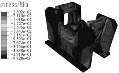
a) Stress
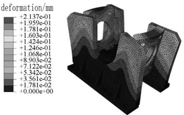
b) Deformation
5. Conclusions
1) According to the requirement of automatic drilling, three kinds of grippers with synchronization devices are designed to improve the traditional gripper. One is a gripper with gear and racks meshing back and forth, the other are a gripper with gear shaft, rack and slip bowl meshing up and down, and the other is a gripper with connecting rods, connecting pieces and slip bowls mutually restricted.
2) Through the finite element analysis of gripper key part, the result shows that the synchronous gripper and parameters selection meet the requirement of the automated drilling rig, and provides a reference for the structural design and optimization of the automated drilling rig gripper.
References
-
Hui H., Lu S., Song H. T. Design and Analysis on a New Clamper for ZDY1200S Drilling Rig. Coal Engineering, Vol. 46, Issue 8, 2014, p. 131-132.
-
Pan H. H. Optimization and test analysis on synchronous clamping mechanism of automatic drilling rig used in coal mine. Coal Mine Machinery, Vol. 47, Issue 2, 2020, p. 124-126.
-
Yang L. Y. Design of normally closed and normally open convertible hydraulic gripper. Coal Mine Machinery, Vol. 47, Issue 2, 2020, p. 121-123.
-
Ke Y., Tian H. L., Yao N. P. Present situation and prospect of drilling equipment technology in coal mine. Coal Geology and Exploration, Vol. 47, Issue 1, 2019, p. 1-5.
-
Yao Y. F., Jie Z., Jian H. Development and application of high efficiency drilling equipment in hard-soft composite coal seam. Coal Science and Technology Engineering, Vol. 46, Issue 4, 2014, p. 76-81.
-
Xiao H. Design and Analysis of Double-tube Drilling Rig’s Clamping and Unclamping Device for Soft Coal Bed. Xi’an University of Science and Technology, 2016.
-
Shi Y. P., Zhou Y. R. ABAQUS Finite Element Analysis Example in Detail, China Machine Press, 2007.
About this article

This research was supported by the National Key Research and Development Program of Xi’an Research Institute of China Coal Technology and Engineering Group No. 2018YFC0808005.
