Abstract
The lateral vibration of drill string causes well deviation and the collision between drill collar and sidewall, and severe lateral vibration even affects the drilling safety or reliability. In view of the problems above, the lateral vibration characteristics of drill string need to be analyzed. Therefore, a newly vibration-collision model of BHA (bottom hole assembly) with random collision characteristics is proposed in this paper. Firstly, the dynamic model of drill collar with double stabilizer is presented by utilizing the Lagrange equations. Secondly, the dynamic characteristics of drill collar in air and mud drilling is analyzed with different collision frequencies. Subsequently, the displacement and motion trajectory of drill collar under different structure parameters of BHA and mechanical parameters of system are investigated by numerical simulation. Finally, the influence of rotation speed of BHA and length of drill collar on lateral vibration of drill collar is discussed. The results indicate that the lateral vibration of drill collar in air drilling is more serious than that in mud drilling; and the higher the collision frequency, the more severe the lateral vibration. Improving rotation speed of BHA, length of drill collar and WOB (weight on bit) have promoting influence on lateral vibration of drill collar; however, increasing stabilizer diameter has suppressing influence on lateral vibration of drill collar. The research findings give reasonable guidance for structure design of BHA and selection of mechanical parameters of system.
Highlights
- A random collision model between stabilizers and sidewall is presented in air drilling.
- A newly vibration-collision model of BHA is proposed to describe the interaction between BHA and sidewall in air drilling engineering.
- The research findings give reasonable guidance for structure design of BHA and selection of mechanical parameters of system.
1. Introduction
In the drilling of vertical well, dual-stabilizer BHA (bottom hole assembly) is widely applied to control the well deviation. However, well deviation is still appeared in the process of air and mud drilling [1-3]. As the transverse vibration of BHA is more acute in air drilling, the well deviation in air drilling process is more severe than that in mud drilling process, which leads to increase of collision frequency between drill collar and sidewall [4, 5]. Therefore, dynamic characteristics of BHA is a complex coupling behavior between vibration and collision in the drill string system. On the vibration analysis of BHA, some ideas can be obtained from the research of Jena et al. [6, 7]. These findings will provide guidance for the follow-up work of drill string mechanics.
Due to the complexity of drilling conditions, the motion of drill string includes axial, torsional and lateral vibration in the actual drilling engineering, furthermore, the lateral vibration of BHA determining the degree of well deviation should be seriously studied [8-10]. To explore the transverse vibration of BHA, many scholars have presented some methods for studying the motion characteristics of BHA, which can give support for analyzing adverse effects caused by transverse vibration of BHA. On account of the high slenderness ratio of the BHA, the transverse vibration model of BHA can be established based on Euler-Bernoulli beam theory; in this case, the governing equation is effectively simplified. The governing equations of transverse vibration of BHA under axial load and interaction with sidewall were established by Yigit et al. by applying the assumed modes method [11, 12]. Chen et al. [13] applied an improved transfer matrix method to analyze the lateral vibration of BHA, which is suitable for drill string subjected to large axial load. Besides, added mass coefficient caused by mud-drill string interaction affecting on lateral vibration is explored. Subsequently, to consider the force caused by bit-rock interaction, a stochastic dynamic approach is introduced into investigation of lateral vibration by Spanos, which can solve the uncertainty of force on the bit [14]. For decreasing the lateral vibration of BHA, Zhu and Di [15] presented a prebent structure of drill collar between the two stabilizers, who demonstrated that the lateral vibration is obviously affected by prebent deflection, and the severe whirling motion of BHA can be effectively prevented by designing a reasonable prebent deflection. On the basis of Zhu’s research, Wang et al. [16] investigated the influence of bend angle on well deviation control mechanism, and the control ability of well deviation is evaluated by the dynamic bit lateral force. Meanwhile, the field experiment shows that the prebent structure of drill collar performs an excellent deviation control effect. However, the above-mentioned articles mainly concentrated on the research of lateral displacement of BHA, the whirling of BHA affected on lateral vibration is neglected. In view of this phenomenon, Marcin et al. [17] adopted a nonsmooth lumped parameter model to analyze the whirling of drill string, and various types of whirling motion are revealed. In the following years, to demonstrate the reliability of model for whirling of drill string, a new type of experimental rig was applied to study the forward and backward whirling of BHA by Marcin et al. [18]. The co-existing state of forward and backward whirling of BHA was firstly observed in experiments. To avoid complicated derivation and solution, the lateral vibration of drill-string was analyzed by many scholars based on finite element method. In addition, the finite element model of drill string can be established with reference to the modeling method by Jena et al. [19]. According to the beam-column theory and finite element method, Wang et al. [20] proposed a model to explore the transverse vibration of BHA, and an indoor experiment was implemented to demonstrate the accuracy of the model. In view of Wang’s research, Li et al. [21] presented a new experimental setup to investigate the lateral motion of BHA, and the motion mechanism of BHA was analyzed. However, the researches above only considered the lateral motion of BHA, and the influence of drill string above BHA was ignored. Consequently, to solve this problem, Li et al. [22] proposed a new model with full-dimensional beam elements by using the finite element method, and the static-kinetic friction model was considered. To better study the dynamic behavior of drill string, Zhu et al. [23] analyzed the buckling response of drill string when the lateral vibration is considered, which can evaluate the critical buckling and working security of drill string. Furthermore, for analyzing the transverse vibration of drill-string in curved well, a beam finite element method was presented by Cai et al. [24]; different with the previous well structure, the curved well consists of vertical section, deflecting section and horizontal section. The above-mentioned research solved many problems existed in the drilling engineering and provided theoretical guidance for the new lateral vibration model, but the vibration-collision mechanism of dual-stabilizer BHA system with random collision characteristics is less explored. Therefore, according to the findings above, a new model with random collision between stabilizers and sidewall is proposed to determine the vibration of BHA; in this case, the relationship among lateral vibration, random collision and parameter variation in the drill string system can be ascertained.
2. Dynamic model of drill collar with double stabilizer
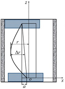
Fig. 1(a) shows the structure of BHA in a vertical well. It usually consists of stabilizers, drill bit and drill collar. Viewed from the positive z axis, the system of drill string rotates clockwise with an angular velocity . In addition, Fig. 1(b) shows the schematic diagram of drill collar cross-section A-A. The transverse vibration of drill collar between double stabilizer is investigated in this paper. To obtain the motion equations of drill collar, the formulas for calculating the virtual work, potential energy and kinetic energy need to be given.
Fig. 1The sketch of the system
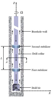
a) The sketch of BHA
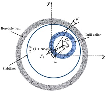
b) Section A-A
2.1. Kinetic energy
The total kinetic energy includes translational energy and rotational kinetic energy of drill collar, which is expressed as:
where, is the length of drill collar between two stabilizers, and are the density of drill collar and circulation medium of drilling, respectively. and are the cross-section area of drill collar and circulation medium inside the drill collar, respectively. and are the velocity of mass center of drill collar and circulation medium at the distance , respectively, which can be given as:
where , and are the displacements in the , and directions, respectively. , and are the unit vectors in the , and directions, respectively. represents the eccentricity of mass center relative to the geometrical center of drill collar. Symbol (·) indicates derivative with respect to time . and indicate the transverse inertia moments of drill-collar with unit length relative to and axes, respectively. indicates the rotational inertia moment of drill-collar with unit length relative to axis. Therefore, the mass inertia moment of drill-collar with unit length are written as:
where, expresses the area inertia moment of drill collar with unit length. , and denote the angular velocity components of drill collar at position in the , and directions, respectively. According to the previous research, the components of angular velocity are written as:
where and represent the rotation angle generated by bending of BHA relative to and axes, respectively. Based on the small deformation hypothesis, and the torsional deformation of drill collar is ignored, the Eq. (5) can be simplified as:
The shear deformation of rotational drill collar is neglected, the rotation angles expressed by the deflection are given as:
Substituting Eqs. (2-7) into the kinetic energy, and the axial vibration is neglected, the equation is deduced as:
By analyzing the regularity of lateral vibration of drill collar, and utilizing the assumed-modes method, the first-order expression of lateral deflection of drill collar is given as:
where, is the radial displacement of drill string at distance /2, which is one of the generalized coordinates of lateral vibration of BHA. Besides, is expressed the rotation angle of radial displacement of drill string, which is another generalized coordinate of lateral vibration of BHA.
Substituting Eq. (9) into Eq. (8), the final form of kinetic energy is obtained as:
2.2. Potential energy
For the drill collar subjected to axial force and bending deformation, the potential energy is given by:
where, is the axial force; in this study, the axial force of drill collar between two stabilizers is approximately equal to WOB (weight on bit). indicates the flexural rigidity of drill collar. Introducing Eq. (9) into Eq. (11), the potential energy is derived as:
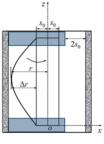
When , the stabilizer will contact the sidewall. Thus, equivalent stiffness of the drill-collar is given by:
where, is the clearance between stabilizer and sidewall. The purpose for solving the stiffness of drill collar is to equivalent the potential energy to a restoring force, which is simplifying the derivation of motion equation of drill collar.
2.3. Virtual work
In this study, the virtual work includes four parts, which are from equivalent restoring force , contact force between drill collar and sidewall , air damping and gyroscopic moment , respectively. The formula of virtual work can be expressed as:
Fig. 2The contact model between stabilizers and sidewall
a) Ipsilateral contact
b) Random contact
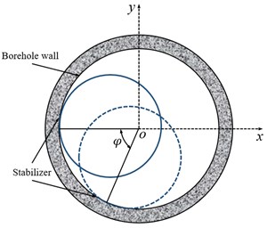
c) Projection in - plane
The virtual work of restoring force can be given as:
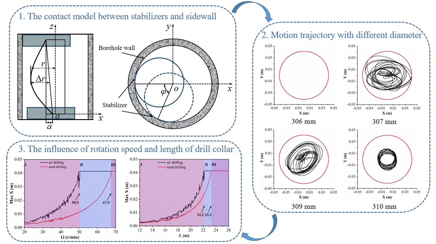
where and indicate the normal component and tangential component of equivalent restoring force , respectively. Besides, the restoring force is generated by the interaction of the stabilizer with the sidewall. In previous studies, the contact model between stabilizers and sidewall shown in Fig. 2(a) was applied to calculate the restoring force, which means that the contact points between two stabilizers and sidewall are in the same plumb line. However, in the actual drilling engineering, the contact points between two stabilizers and sidewall are in different plumb line, in this case, there is an offset distance between the geometric centers of the case two stabilizers in the x direction, as displayed in Fig. 2(b). Fig. 2(c) shows the projection of the contact position between two stabilizers and sidewall in - plane, where is the phase angle between two stabilizers and sidewall contact point. When the contact between stabilizers and sidewall is ipsilateral, the phase angle is 0; when the contact between stabilizers and sidewall is random, the phase angle is ranged from 0 to . According to geometric relationship, the expression for the offset distance of geometric centers of the two stabilizers in terms of the phase angle is written as:
When the friction between stabilizer and sidewall is ignored, the restoring force is written as:
However, the friction between stabilizer and sidewall is considered, the restoring force is indicated as:
where, is the angle displacement of rotation of geometrical center of drill collar relative to geometrical center of stabilizer. is the friction angle caused by the contact between stabilizer and sidewall. The friction angle can be confirmed based on the law of Coulomb friction. In addition, the geometric relationship of and is obtained by:
When stabilizer contacts with the wall of well, the normal component and tangential component of equivalent restoring force are given as:
When the lateral displacement is large enough, the drill collar will contact with sidewall. On the basis of the Hertz contact law, the normal force is written as:
where is the contact coefficient, is the clearance between drill collar and sidewall. Furthermore, the tangential force is indicated as:
where denotes the friction coefficient, is the outer radius of drill collar.
Thus, the virtual work generated by contact force is written as:
The damping force will be generated when the drill collar vibrates, the virtual work of the damping force is expressed as:
The normal and tangential components of the damping force are written as follow:
with , where is the damping coefficient.
The drill collar rotates about its own axis; thus, gyroscopic moment will be occurred when the axis is deflected. The virtual work from gyroscopic moment can be expressed as:
Substituting Eqs. (4), (7) and (9) into Eq. (28), the result of virtual work from gyroscopic moment is derived as:
Therefore, the total generalized forces of system from virtual work can be obtained as:
2.4. Governing equations
In this study, to acquire the motion equations of drill collar, the expressions of Lagrange equations are adopted as:
By applying Lagrange equations, the governing equations are obtained as follow:
with:
3. Numerical simulation
The dynamic model of lateral vibration of drill collar has been established in the previous section. To demonstrate the applicability of the theoretical analysis and dynamic model, in this section, the simulation results of dynamic characteristics of drill collar are given. In the actual drilling engineering, the collision between stabilizers and sidewall is random, and the phase angle is ranged from 0 to ; in this case, the collision frequency between stabilizers and sidewall is regarded as , i.e., the phase angle is changed in every 1/ second. To better satisfy this condition, the random function is introduced to solve dynamic equations. Consequently, the phase angle can be written as:
where, is the random function and ranges from 0 to 1, is the integral time. The dynamic characteristics of drill collar are analyzed in air drilling and mud drilling when the collision frequency is 0.2, 1 and 5 Hz, respectively. The structural parameters of the BHA are listed in Table 1, the mechanical parameters of the system are given in Table 2.
Table 1Structural parameters of BHA
Property | Value | Units |
Young’s modulus of drill collar | 210 | GPa |
Density of drill collar | 7860 | Kg/m3 |
Length of drill collar | 21 | m |
Outer diameter of drill collar | 228.6 | mm |
Inner diameter of drill collar | 76.2 | mm |
Eccentricity of drill collar | 12.7 | mm |
Diameter of stabilizer | 308 | mm |
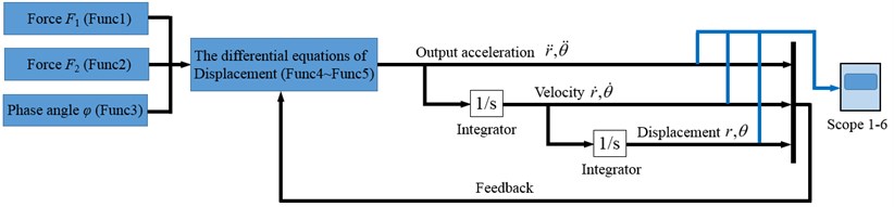
The Runge-Kutta method, as a high-precision algorithm, is widely applied in complex nonlinear calculation. Hence, in the numerical simulation of this paper, Runge-Kutta method is applied to solve the dynamic equations. The flow chart of the numerical simulation of the dynamic model is shown in Fig. 3. Firstly, the phase angle is determined by the collision frequency. Secondly, the forces and are obtained based on the judgment conditions. Subsequently, the forces are introduced to the governing equations. Finally, the acceleration, velocity and displacement can be calculated according to the Runge-Kutta method. All data will be saved in the blue box on the right of Fig. 3, which is an observation device.
Table 2Mechanical parameters of the system
Property | Value | Units |
Weight on bit | 20 | kN |
Rotation speed | 45 | r/min |
Density of compressed air | 50 | kg/m3 |
Diameter of borehole | 311.2 | mm |
Contact coefficient | 6.78×10¹¹ | Nm-1.5 |
Friction angle | 0.5 | ° |
Friction coefficient | 0.2 | |
Damping coefficient | 1 |
Fig. 3The flow chart of the numerical simulation of the dynamic model
3.1. The dynamic characteristics of drill collar under different collision frequencies
3.1.1. Air drilling
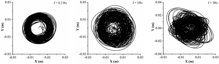
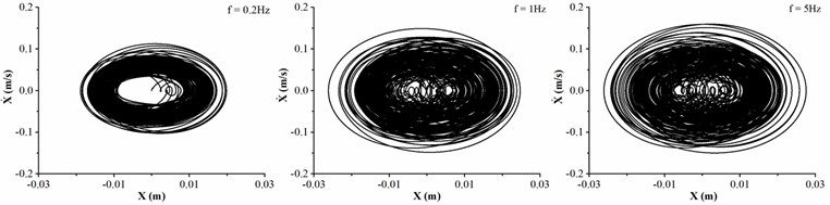
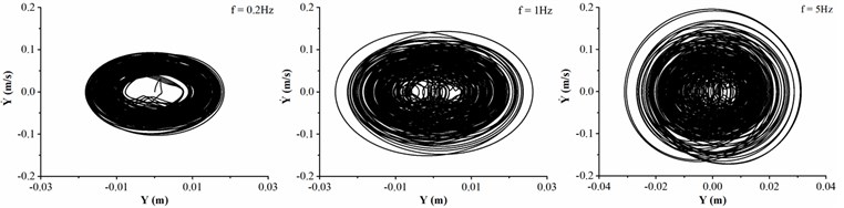
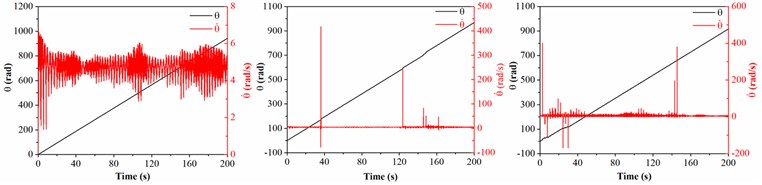
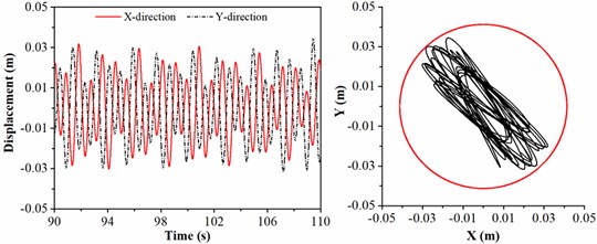
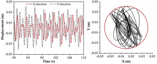
The dynamic characteristics of drill collar in air drilling is shown in Fig. 4 when the collision frequency between stabilizers and sidewall are 0.2, 1 and 5 Hz, respectively. Fig. 4(a) shows the motion trajectory of geometric center of drill collar, it can be found that the trajectory is chaotic, and the collision between drill collar and sidewall is frequently occurred. Meanwhile, the final motion trajectory of drill collar under all conditions is circular. With the increase of collision frequency between stabilizers and sidewall, the trajectory curve is more chaotic, and the lateral displacement of drill collar is more severe. Fig. 4(b) and (c) show the phase trajectory of drill collar in and directions, respectively, and the maximum velocities in two directions are consistent under the same frequency collision. Besides, in the case of low frequency collision, the maximum lateral velocity is decreased comparing with frequent frequency collision. In Fig. 4(d), the black solid line represents the whirling angle, when the slope of black line is positive, this phenomenon means that the average whirling speed is positive, i.e., the drill collar is forward whirling; when the slope of black line is negative, this suggests that the average whirling speed is negative, i.e., the drill collar is backward whirling. Meanwhile, the whirling angle increases initially and decreased afterwards under different collision frequencies, which demonstrates that the drill collar is first forward whirling, and then backward whirling. However, it takes more time when the drill collar reaches the backward whirling under high collision frequency. Furthermore, the slope of black line is changed with the variation of average whirling speed of drill collar. The red solid line represents the whirling speed of drill collar, it is seen that numerous spikes are appeared, which can be explained by Fig. 4(a). In trajectory curve diagram, the geometric center of drill collar frequently passes by the center of borehole, in this case, the whirling radius of drill collar is become small. As the whirling speed of drill collar is inversely proportional to whirling radius of drill collar, thus, the whirling speed of drill collar will appear peak value. The number of peak value of whirling speed is increased with the collision frequency, and the inflection point related to the average whirling speed is increased accordingly. When the motion state of drill collar from forward whirling to backward whirling, the backward whirling speed is maintained around 13 rad/s, which is three times of the rotation speed of BHA. Therefore, it can be concluded that lower collision frequency is beneficial to decrease lateral displacement of drill collar, however, the lower collision frequency is more likely to induce the backward whirling of drill collar.
Fig. 4Dynamic characteristics of drill collar in air drilling with different collision frequency
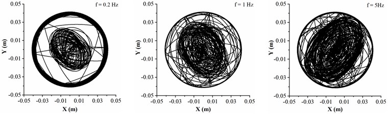
a) Motion trajectory
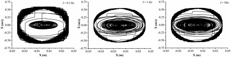
b) Phase trajectory in direction
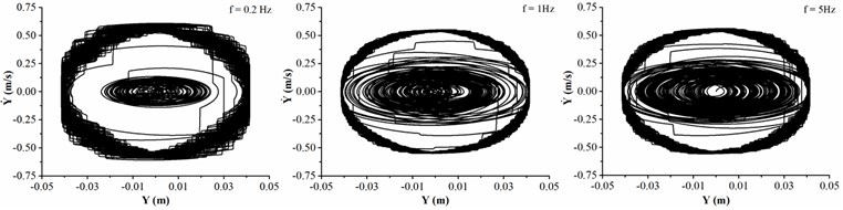
c) Phase trajectory in direction
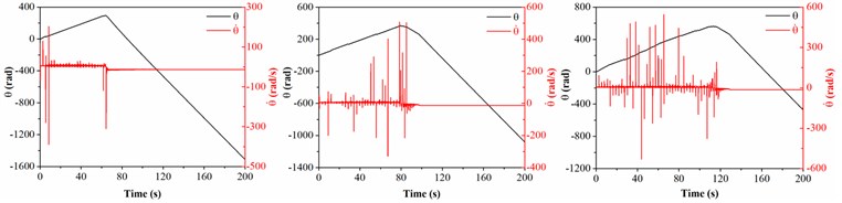
d) Whirling speed and angle
3.1.2. Mud drilling
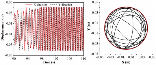
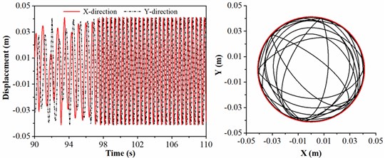
Different from the air drilling, the friction coefficient is given as 0.1 and the density of drilling fluid is treated as 1500 kg/m3 in mud drilling. Fig. 5 shows the dynamic characteristics of drill collar in mud drilling when the collision frequency between stabilizers and sidewall is chosen as 0.2, 1 and 5 Hz, respectively.
Fig. 5Dynamic characteristics of drill collar in mud drilling with different collision frequency
a) Motion trajectory
b) Phase trajectory in direction
c) Phase trajectory in direction
d) Whirling speed and angle
Fig. 5(a) displays the motion trajectory of geometric center of drill collar, and it is found that the lateral displacement of drill collar is increased with the increase of collision frequency. Furthermore, the maximum lateral displacement is less than the clearance between drill collar and sidewall, under the circumstances, the contact between drill collar and sidewall is disappeared. When the collision frequency is up to 5 Hz, the displacement of drill collar in direction is significantly greater than the displacement in direction. In the light of Fig. 5(b) and (c), the velocities in two directions are both increased with the collision frequency, and the lateral velocity is no more than 0.2 m/s. The lateral velocity of drill collar in the mud drilling is much smaller than air drilling process. As shown in Fig. 5(d), the whirling angle is increased with the time, which means that the average whirling speed is always positive, i.e., the drill collar is always forward whirling. When the collision frequency is 0.2 Hz, there is no spikes in whirling speed curve of drill collar because the geometric center of drill collar is deviated from the center of borehole according to trajectory curve diagram. With the increase of collision frequency between stabilizers and sidewall, the number of peak value of whirling speed is increased; besides, the number of inflection points is increased, i.e., the number of average whirling speed changes is increased. Compared with air drilling process, the whirling speed of drill collar mainly fluctuates near the rotation speed in mud drilling, and the backward whirling of drill collar is accidentally happened. Therefore, to reduce the lateral displacement and lateral velocity of drill collar, the collision frequency between stabilizers and sidewall should be controlled.
The previous section, the dynamic characteristics of drill collar under different collision frequencies are explored in air and mud drilling process, respectively. It is obviously found that lateral displacement and velocity in air drilling are greater than that in mud drilling, and the collision between drill collar and sidewall will be happened in air drilling. Meanwhile, the whirling angle increases initially and decreased afterwards in air drilling; however, the whirling angle is always increased in mud drilling. Hence, the backward whirling of drill collar is more likely to occur in air drilling process. Besides, to further analyze the dynamic behavior of drill collar in different structure and mechanical parameters, the lateral displacement and motion trajectory of drill collar are given. Since the influence of structure and mechanical parameters of the system on lateral vibration during mud drilling has been discussed several times in previous studies, thus, only the lateral vibration of drill collar in air drilling will be analyzed below. It can provide theoretical guidance to control the well deviation of trajectory.
3.2. The lateral displacement of drill collar under different diameters of stabilizer
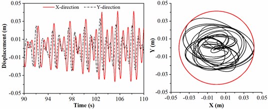
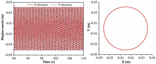
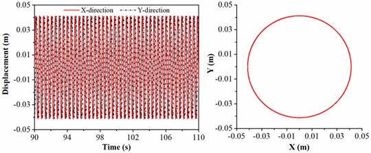
To explore the drill collar lateral vibration affected by the size of stabilizer, the stabilizer diameter is treated as 306, 307, 309 and 310 mm, respectively. The rotation speed of BHA, length of drill collar and WOB are given by 45 r/min, 21 m and 20 kN. As shown in Fig. 6, the displacement and the trajectory curve of geometric center of drill collar are discussed. In right part of Fig. 6(a), the motion trajectory of drill collar represented by the black curve is overlapped with clearance between drill collar and sidewall represented by the red circle, which means that drill collar always contacts the sidewall; in this situation, the lateral displacement of drill collar is maximum, and same conclusion can be seen in time-displacement curve. In Fig. 6(b), the displacement in direction is larger than direction, and the collision between drill collar and sidewall is occurred. When the diameter of the stabilizer is 309 mm, the lateral displacement of drill collar is displayed in Fig. 6(c), and it can be observed that the displacements in and directions are always less than the clearance between drill collar and sidewall. As shown in Fig. 6(d), the motion trajectory of drill collar is mainly concentrated in near the center of borehole, and the motion trajectory is approximated to a circle; in this case, the variation ranges of displacement in and directions are almost identical. Therefore, the larger the diameter of stabilizer, the smaller the lateral vibration of drill collar; and the simulation result is consistent with the actual working conditions.
According to the numerical results, the lateral displacement is decreased with the diameter of stabilizer, therefore, to deduce the lateral vibration of BHA in air drilling, the larger diameter of stabilizer should be chosen. Besides, the influence of diameter of stabilizer on lateral displacement of drill collar is significant. In Fig. 6(a) and (d), the difference in stabilizer diameter is 4mm; however, the lateral displacement in 6(a) is greatly larger than 6(d).
3.3. The lateral displacement of drill collar under different rotation speeds
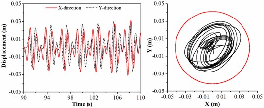
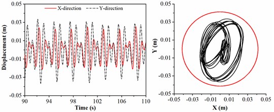
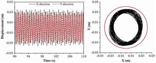
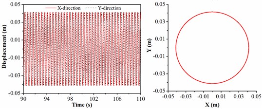
To investigate the rotation speed affected on the lateral vibration of drill collar, the rotation speed is chosen as 35, 40, 45 and 50 r/min, respectively; and the diameter of stabilizer, length of drill collar and WOB are given by 308 mm, 21 m and 20 kN. Fig. 7 shows the motion trajectory of geometric center of drill collar under different rotation speeds. As shown in Fig. 7(a), the lateral displacement of drill collar in direction ranges from –0.01 to 0.01m, and the lateral displacement of drill collar in direction ranges from –0.03 to 0.03m. Hence, the drill collar is not contact with the sidewall. In Fig. 7(b), it can be found that the peak values of displacement in and direction are consistent; the drill collar contacts with sidewall, however, the collision frequency is small. When the rotation speed is 45 r/min, Fig. 7(c) shows the displacement of geometric center of drill collar, and the motion trajectory is complicated; besides, with the increase of time, the lateral displacement of drill collar will reach the maximum. Fig. 7(d) shows the motion trajectory of drill collar when the rotation speed is 50 r/min; but the red circle is only displayed in trajectory diagram, which means that the black curve is overlapped with red circle. In this case, the drill collar is always in contact with sidewall. Based on the analysis above, increasing rotation speed can promote the lateral vibration of drill collar. Therefore, to avoid the collision between drill collar and sidewall and backward whirling of drill collar, when the ROP (rate of penetration) requirement is satisfied in practical engineering, a smaller rotation speed should be chosen.
Fig. 6Motion trajectory of drill collar under different diameters of stabilizer
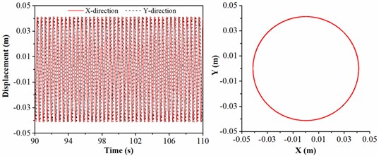
a)306 mm
b) 307 mm
c) 309 mm
d) 310 mm
Fig. 7Motion trajectory of drill collar under different rotation speeds
a) 35 r/min
b) 40 r/min
c) 45 r/min
d) 50 r/min
3.4. The lateral displacement of drill collar under different WOB
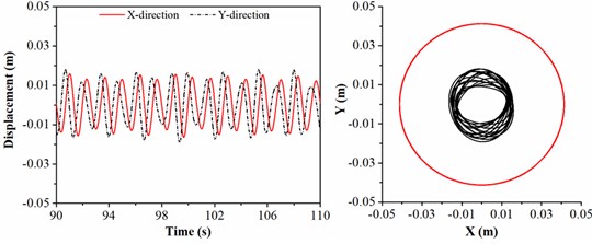
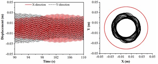
To analyze the influence of WOB on lateral vibration of drill collar, the WOB is considered as 10, 15, 20 and 25 kN, respectively; and the rotation speed of BHA, length of drill collar and diameter of stabilizer are given by 45 r/min, 21 m and 308 mm. The lateral displacement and motion trajectory of geometric center of drill collar under different WOB are shown in Fig. 8.
As shown in Fig. 8, with the rising of WOB, the lateral displacement of drill collar is increased. In Fig. 8(a), the motion trajectory of drill collar represented by the black curve is completely limited in the red circle representing the clearance between drill collar and sidewall, thus, there is no collision between drill collar and sidewall; in addition, the whirling motion of drill collar is irregular.
Fig. 8Motion trajectory of drill collar under different WOB
a) 10 kN
b) 15 kN
c) 20 kN
d) 25 kN
In the light of Fig. 8(b), the largest displacement in direction is equal to the value of clearance between drill collar and sidewall; besides, the chaotic motion of drill collar is more obvious, and the collision between drill collar and sidewall is happened several times. When WOB is 20 kN, the motion state of drill collar becomes more complicated; the motion of drill collar is irregular 98 seconds ago, however, the displacements in and directions will be maximum after 98 seconds, in this case, the motion trajectory of drill collar is a circle. Fig. 8(d) shows the motion trajectory of drill collar when WOB is 25 kN, the black curve representing the motion trajectory of drill collar is covered by the red circle representing the clearance between drill collar and sidewall; in this situation, the drill collar is always in contact with sidewall. According to the above-mentioned discussion, it is found more severe lateral vibration will be appeared if large WOB is given in the actual drilling operation. Therefore, for avoiding the buckling of drill string and limiting the lateral vibration of drill collar, a reasonable WOB satisfying rock breaking efficiency should be applied in the air drilling engineering.
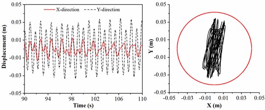
Fig. 9Motion trajectory of drill collar under different lengths of drill collar
a) 12 m
b) 16.5 m

c) 21 m
d) 25.5 m
3.5. The lateral displacement of drill collar under different lengths of drill collar
In actual drilling engineering, length of drill collar is one of the significant factors affecting the lateral vibration of drill collar. The length of drill collar is treated as 12, 16.5, 21 and 25.5 m, respectively; and the rotation speed of BHA, diameter of stabilizer and WOB are given by 45 r/min, 308 mm and 20 kN. Fig. 9 shows the displacement and motion trajectory of geometric center of drill collar under different lengths of drill collar. As shown in Fig. 9(a) and 9(b), the motion trajectory of drill collar is similar to a circle, and it is always limited in the red circle; meanwhile, the radius of motion trajectory of drill collar in Fig. 9(b) is larger than Fig. 9(a), which means that the lateral displacement of drill collar in 9(b) is severe than 9(a). When the drill collars between the two stabilizers is 21 m, the motion trajectory of drill collar is shown in Fig. 9(c); it is evident that the motion trajectory of drill collar becomes chaotic, and the displacement gradually increases to the maximum. When the length of drill collar between the stabilizers is 25.5m, the lateral displacement of drill collar is maximum, and the motion trajectory of drill collar is a circle, which indicates that drill collar is rotated and contacted with the sidewall all the time. On the basis of analysis above, the length of drill collar has promoting influence on lateral vibration of drill collar, i.e., the longer the length of drill collar, the greater the lateral displacement. It can be concluded that length of drill collar between the two stabilizers should be decreased to control severe lateral vibration of drill collar.
4. Parametric analysis
To further understand the influence of rotation speed of BHA and length of drill collar on lateral vibration of drill collar, the parametric analysis will be carried out with numerical computations. The deflection capacity of BHA is positively related to the lateral displacement of drill collar, therefore, the maximum displacements of drill collar in and directions are discussed by changing the structure parameters of the BHA and mechanical parameters of the drill string system.
4.1. Influence of rotation speed of BHA
A fixed length drill collar is assumed when analyzing the influence of rotation speed on lateral vibration of drill collar under a constant WOB. The relationship between lateral displacements in , directions and rotation speed are shown in Fig. 10.
Fig. 10The response amplitude of drill collar lateral vibration related to rotation speed Ω
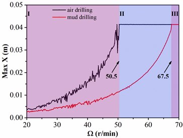
a) The maximum lateral displacement in direction
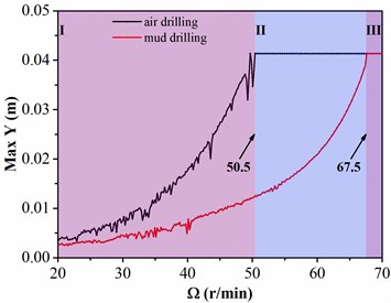
b) The maximum lateral displacement in direction
To sum up, the variation tendency of displacements in the two directions are approximately identical. The figure is divided into three regions; the maximum lateral displacements in air and mud drilling are both increased with the rotation speed in region Ⅰ, but the maximum lateral displacement in air drilling is always greater than that in mud drilling. When the rotation speed is arrived in 50.5 r/min, the maximum lateral displacement in air drilling is approached to the value of clearance between drill collar and sidewall; however, the maximum lateral displacement in mud drilling is only increased to 0.01 m, which is far less than the clearance between drill collar and sidewall. In region Ⅱ, the maximum lateral displacement in air drilling remains unchanged with the rising of rotation speed of BHA; while the maximum lateral displacement in mud drilling is still increased with the rotation speed. The critical rotation speed between Ⅱ and Ⅲ regions is 67.5 r/min; when the rotation speed is continually increased and larger than critical rotation speed of BHA, the maximum lateral displacements in air and mud drilling are remained constant. According to the above-mentioned analysis, the lateral displacement of drill collar in mud drilling is smaller than that in air drilling in the same rotation speed, and the rotation speed of BHA making drill collar contacted with sidewall in mud drilling is larger than air drilling. Besides, the rotation speed of BHA is positively correlated to the lateral vibration of drill collar. Therefore, a small rotation speed of BHA is beneficial to reduce the lateral vibration of drill collar.
4.2. Influence of length of drill collar
The lateral vibration of drill collar affected by length of drill collar is explored when the rotation speed and WOB are 45 r/min and 20 kN, respectively. Fig. 11 shows the relationship between lateral displacements and the length of drill collar, where the black line indicates the air drilling and the red line represents the mud drilling.
Fig. 11The response amplitude of drill collar lateral vibration related to length of drill collar L
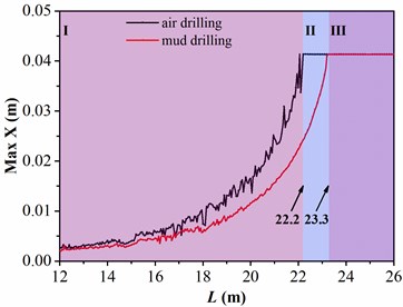
a) The maximum lateral displacement in direction
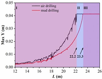
b) The maximum lateral displacement in direction
Besides, the variation tendency of displacements in the two directions are approximately identical, and the figure is likewise divided into three regions. In region Ⅰ, the maximum lateral displacements in air and mud drilling are both increased with the length of drill collar; however, the growth rate of maximum lateral displacement in mud drilling is less than that in air drilling. When the length of drill collar is arrived in 22.2 m, the maximum lateral displacement is increased to 0.0413 m in air drilling, in this situation, the drill collar is in contact with sidewall; while the maximum lateral displacement in mud drilling is only increased to 0.024 m, which is always less than the value of clearance between drill collar and sidewall. In region Ⅱ, the maximum lateral displacement in air drilling keeps unchanged with the increase of length of drill collar; however, the maximum lateral displacement is increased with length of drill collar in mud drilling. The critical length of drill collar between Ⅱ and Ⅲ regions is 23.3 m, the maximum lateral displacements in air and mud drilling are unaltered with the increase of length of drill collar when the length of drill collar is greater than the critical length. Based on the analysis above, the lateral vibration of drill collar in air drilling is more serious than mud drilling in same length of drill collar, and the length of drill collar making drill collar arrived in the maximum lateral displacement in air drilling is shorter than mud drilling. Furthermore, the length of drill collar is positively correlated to the lateral displacement of drill collar. Therefore, to avoid the severe lateral vibration of drill collar, the length of drill collar between two stabilizers should be reduced.
5. Conclusions
For the adverse effects caused by the lateral vibration of BHA, such as excessive well deviation and collision between drill string and sidewall, a newly dynamic model of drill collar with random collision between stabilizers and sidewall is presented in this article. Lateral vibration of drill collar affected by the structure parameters of the BHA and the mechanical parameters of system are analyzed by the numerical simulation. Some conclusions are given as follow:
1) The lateral vibration of drill collar is more severe in air drilling, and the collision between drill collar and sidewall is more likely to occur. In addition, the backward whirling of drill collar will be occurred in air drilling, and the backward whirling speed is approached to the three times as much as the rotation speed of BHA.
2) The relationship between lateral vibration of drill collar and collision frequency is studied. The higher the collision frequency, the more severe the lateral vibration of drill collar, and the more the spikes of whirling speed.
3) The diameter of stabilizer is negatively correlated with the lateral vibration of drill collar; however, the rotation speed of BHA, WOB and length of drill collar are positively correlated to the lateral vibration of drill collar.
4) Research indicates that the lateral vibration of drill collar is significantly affected by the drilling parameters, and the findings will provide theoretical support for structure design of BHA and selection of mechanical parameters of the system.
5) The reliability of proposed model is proved by the numerical simulation results, thus the research findings can provide reasonable guidance for the dynamic model of BHA with double or multi span drill collar in future work.
References
-
D. Gao and D. Zheng, “Study of a mechanism for well deviation in air drilling and its control,” Petroleum Science and Technology, Vol. 29, No. 4, pp. 358–365, Jan. 2011, https://doi.org/10.1080/10916466.2010.493906
-
Z. Li, C. Zhang, and G. Song, “Research advances and debates on tubular mechanics in oil and gas wells,” Journal of Petroleum Science and Engineering, Vol. 151, pp. 194–212, Mar. 2017, https://doi.org/10.1016/j.petrol.2016.10.025
-
D. Zhang, M. Wu, C. Lu, L. Chen, and W. Cao, “A deviation correction strategy based on particle filtering and improved model predictive control for vertical drilling,” ISA Transactions, Vol. 111, No. 1, pp. 265–274, May 2021, https://doi.org/10.1016/j.isatra.2020.11.023
-
Z. Lian, Q. Zhang, T. Lin, and F. Wang, “Experimental and numerical study of drill string dynamics in gas drilling of horizontal wells,” Journal of Natural Gas Science and Engineering, Vol. 27, pp. 1412–1420, Nov. 2015, https://doi.org/10.1016/j.jngse.2015.10.005
-
M. Sarker, D. G. Rideout, and S. D. Butt, “Dynamic model for 3D motions of a horizontal oilwell BHA with wellbore stick-slip whirl interaction,” Journal of Petroleum Science and Engineering, Vol. 157, pp. 482–506, Aug. 2017, https://doi.org/10.1016/j.petrol.2017.07.025
-
P. Charan Jena, “Identification of crack in SiC composite polymer beam using vibration signature,” Materials Today: Proceedings, Vol. 5, No. 9, pp. 19693–19702, 2018, https://doi.org/10.1016/j.matpr.2018.06.331
-
S. P. Parida and P. C. Jena, “Selective layer-by-layer fillering and its effect on the dynamic response of laminated composite plates using higher-order theory,” Journal of Vibration and Control, p. 107754632210811, Apr. 2022, https://doi.org/10.1177/10775463221081180
-
A. Ghasemloonia, D. Geoff Rideout, and S. D. Butt, “A review of drillstring vibration modeling and suppression methods,” Journal of Petroleum Science and Engineering, Vol. 131, pp. 150–164, Jul. 2015, https://doi.org/10.1016/j.petrol.2015.04.030
-
J. Tian, Y. Yang, and L. Yang, “Vibration characteristics analysis and experimental study of horizontal drill string with wellbore random friction force,” Archive of Applied Mechanics, Vol. 87, No. 9, pp. 1439–1451, Sep. 2017, https://doi.org/10.1007/s00419-017-1262-9
-
P. K. Saraswati, S. Sahoo, S. P. Parida, and P. C. Jena, “Fabrication, characterization and drilling operation of natural fiber reinforced hybrid composite with filler (Fly-Ash/Graphene),” International Journal of Innovative Technology and Exploring Engineering, Vol. 8, No. 10, pp. 1653–1659, Aug. 2019, https://doi.org/10.35940/ijitee.j1253.0881019
-
A. S. Yigit and A. P. Christoforou, “Coupled axial and transverse vibrations of oilwell drillstrings,” Journal of Sound and Vibration, Vol. 195, No. 4, pp. 617–627, Aug. 1996, https://doi.org/10.1006/jsvi.1996.0450
-
A. P. Christoforou and A. S. Yigit, “Dynamic modelling of rotating drillstrings with borehole interactions,” Journal of Sound and Vibration, Vol. 206, No. 2, pp. 243–260, Sep. 1997, https://doi.org/10.1006/jsvi.1997.1091
-
S. L. Chen and M. Géradin, “An improved transfer matrix technique as applied to BHA lateral vibration analysis,” Journal of Sound and Vibration, Vol. 185, No. 1, pp. 93–106, Aug. 1995, https://doi.org/10.1006/jsvi.1994.0365
-
P. D. Spanos, A. M. Chevallier, and N. P. Politis, “Nonlinear stochastic drill-string vibrations,” Journal of Vibration and Acoustics, Vol. 124, No. 4, pp. 512–518, Oct. 2002, https://doi.org/10.1115/1.1502669
-
Z. Weiping and D. Qinfeng, “Effect of prebent deflection on lateral vibration of stabilized drill collars,” SPE Journal, Vol. 16, No. 1, pp. 200–216, Mar. 2011, https://doi.org/10.2118/120455-pa
-
W. Wang et al., “The dynamic deviation control mechanism of the prebent pendulum BHA in air drilling,” Journal of Petroleum Science and Engineering, Vol. 176, pp. 521–531, May 2019, https://doi.org/10.1016/j.petrol.2019.01.008
-
M. Kapitaniak, V. Vaziri, J. Páez Chávez, and M. Wiercigroch, “Numerical study of forward and backward whirling of drill-string,” Journal of Computational and Nonlinear Dynamics, Vol. 12, No. 6, p. 06100, Nov. 2017, https://doi.org/10.1115/1.4037318
-
M. Kapitaniak, V. Vaziri, J. Páez Chávez, and M. Wiercigroch, “Experimental studies of forward and backward whirls of drill-string,” Mechanical Systems and Signal Processing, Vol. 100, pp. 454–465, Feb. 2018, https://doi.org/10.1016/j.ymssp.2017.07.014
-
S. P. Parida, P. C. Jena, S. R. Das, D. Dhupal, and R. R. Dash, “Comparative stress analysis of different suitable biomaterials for artificial hip joint and femur bone using finite element simulation,” Advances in Materials and Processing Technologies, pp. 1–16, Jul. 2021, https://doi.org/10.1080/2374068x.2021.1949541
-
H. Wang et al., “Modeling and analyzing the motion state of bottom hole assembly in highly deviated wells,” Journal of Petroleum Science and Engineering, Vol. 170, pp. 763–771, Nov. 2018, https://doi.org/10.1016/j.petrol.2018.07.005
-
W. Li, G. Huang, H. Ni, F. Yu, B. Huang, and W. Jiang, “Experimental study and mechanism analysis of the motion states of bottom hole assembly during rotary drilling,” Journal of Petroleum Science and Engineering, Vol. 195, p. 107859, Dec. 2020, https://doi.org/10.1016/j.petrol.2020.107859
-
W. Li, G. Huang, F. Yu, H. Ni, W. Jiang, and X. Zhang, “Modeling and numerical study on drillstring lateral vibration for air drilling in highly-deviated wells,” Journal of Petroleum Science and Engineering, Vol. 195, p. 107913, Dec. 2020, https://doi.org/10.1016/j.petrol.2020.107913
-
X.-H. Zhu and B. Li, “Numerical simulation of dynamic buckling response considering lateral vibration behaviors in drillstring,” Journal of Petroleum Science and Engineering, Vol. 173, pp. 770–780, Feb. 2019, https://doi.org/10.1016/j.petrol.2018.09.090
-
M. Cai, L. Mao, X. Xing, H. Zhang, and J. Li, “Analysis on the nonlinear lateral vibration of drillstring in curved wells with beam finite element,” Communications in Nonlinear Science and Numerical Simulation, Vol. 104, p. 106065, Jan. 2022, https://doi.org/10.1016/j.cnsns.2021.106065
Cited by
About this article

The research leading to these results received funding from [the PetroChina Innovation Foundation] under Grant Agreement No. [2020D-5007-0312] and [the PetroChina-Southwest Petroleum University Innovation Consortium Project] under Grant Agreement No. [2020CX040103].
The datasets generated during and/or analyzed during the current study are available from the corresponding author on reasonable request.
Pan Fang: conceptualization, writing – review and editing; Kang Yang: methodology, writing – original draft preparation; Gao Li: funding acquisition, resources; Qunfang Feng: data curation; Shujie Ding: software.
The authors declare that they have no conflict of interest.
