Abstract
Annular drilling fluid between the drillstring and borehole wall has a great influence on lateral vibration of drillstring and the influence involves the added mass. Assuming the drilling fluid is incompressible, we derive the added mass coefficient that annular drilling fluid influences on lateral vibration of drillstring in the case of axial flow of drilling fluid. When the axial flow of drilling fluid is considered, the added mass coefficient is difficult to solve. We apply CFD method and dynamic mesh technique to establish the calculation model for the flow in the annulus caused by the vibration of drillstring in the annulus. The pressure distribution and velocity distribution of annular drilling fluid are obtained. The added mass force of the drilling fluid acting on the drillstring along the direction of the drillstring is obtained from the pressure distribution, and the added mass coefficient of the lateral vibration of the drillstring is obtained. This paper provides the basis to solve the added mass coefficient of the lateral vibration of drillstring considering axial flow of drilling fluid.
Highlights
- The added mass coefficient of the annular drilling fluid’s influence on the lateral vibration of the drillstring is derived
- Using CFD method and dynamic mesh technology to simulate the annular flow caused by the vibration of drillstring in the annular drilling fluid under two-dimensional conditions
- Providing the basis to solve the added mass coefficient that drillstring of lateral vibration under consideration of axial flow
1. Introduction
It has been proved that drilling dynamics and its interactions with the surroundings are the essential reason of a lot of dangerous drilling accidents, such as the poor cementing quality induced by the deterioration of borehole quality and the failure of drilling tools caused by strong vibration [1, 2]. As the most common dynamics phenomenon, severe vibrations of drillstring must be paid enough attention. The drillstring is consisted of several drill pipes, drill collars, stabilizers and connections, both are under heavy dynamic loads with extreme complexity. If the excited frequency of drillstring closes to the natural frequencies of its components, the energy will be absorbed. Once the resonance appears and the energy boosts, the amplitude of drillstring vibration will be increased, and the bending of drillstring will be intensified, by which the early fatigue of tools will occur [3], and the tools life will be reduced significantly. There are three typical modes of drillstring vibration, namely are the longitudinal vibration (also called axial vibration) mode, the transverse (also referred to lateral or bending) mode and the torsional (also known as stick-slip) mode. The destructive nature of each type of vibration is different, it is well known that lateral vibration [4] is the main reason for drillstring failure as the study of drillstring dynamics goes further. Many dangerous phenomena related to drilling are normally caused by the dynamics of the drillstring and its interactions with the surroundings.
The destructive nature of each type of vibration is different, among them, the longitudinal vibration owns the most intuitionistic destructive behavior and action. The axial vibration of the drillstring can be defined using discrete mass segments and springs [5] and the frequency response function can be used to demonstrate the similarity of the model to the real drillstring response. Aadnoy et al. [6] studies using the static model of the drillstring and the rotation of the drillstring to reduce the drillstring borehole friction during torsional vibration. Wolf S. F. et al. [7] measured down hole parameters like bottom force and acceleration during vertical drilling, and it was found that resonant frequency of the system is lower than intrinsic frequency of drillstring [8]. The bending moment obtained by static simulation is one order of magnitude smaller than the real one, and a high bending moment was observed at the bottom which cannot be surveyed at the wellhead [9]. Qilong X. et. al. [10-11] studied the effect of annulus drilling fluid damping on drillstring lateral vibration, and it was found that the additional quality caused by drilling fluid is at the same order of magnitude of the quality of drillstring, which cannot be neglected. Some studies are dedicated to better understanding the full dynamics of rotary drilling systems [12-14]. Sunit [15] develops the global dynamics of coupled axial torsional vibration and the possibility of bit bounce. Brebbia [16] used the boundary element method of solid mechanics to calculate velocity potential in fluid flow, which makes the calculation method simpler. Sarpkaya [17, 18] studied the added mass of cylindrical vortex-induced oscillation (VIO) through experiments. It was found that the added mass varied greatly with the ratio of amplitude to diameter, and the added mass was negative at some time. Villaggio [19] calculated the added mass of an infinite cylinder with elastic deformation, but the elastic vibration was not considered in the calculation process. Heisig G. et al. [20] studied the impact between drillstring and borehole wall and deduced the lateral vibration model of drillstring.
During the downward movement of the drillstring, the lateral vibration of the drillstring is the most complex movement of the drillstring vibration, and the drilling fluid in the drillstring and the borehole annulus is the main factor causing the lateral vibration of the drillstring. Lateral vibration is mainly caused by drillstring deformation which is caused by fluid-solid coupling and interrelation between drilling fluid and drillstring. Added mass is usually involved in solving fluid-solid coupling systems. None of works has obtained added mass coefficients in the case of axial motion. This paper mainly analyses the mass effect of annular drilling fluid on drillstring lateral resonance and calculates added mass coefficients by potential flow theory under the condition of axial motion, which provides a reference for engineering application of drilling process.
2. Methods and models
2.1. Basic assumptions
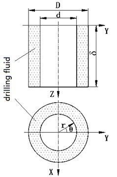
Assuming the diameter of the drillstring is , the diameter of the borehole wall is , and the axial direction of the drillstring is the direction, as shown in Fig. 1. If the lateral movement of the drillstring is a harmonic motion in the Y direction, the displacement of the drillstring can be expressed by the following formula:
where is the amplitude of the drillstring vibration, is the frequency of the drillstring vibration, and is the time, .
Assuming that the fluid is homogeneous and incompressible, the sound velocity in the drilling fluid is considered to be very fast, and ignoring the influence of the vibration frequency of the drillstring, there is a velocity potential function and the following formula is satisfied:
In the formula, is a Laplacian operator, is a potential function of velocity and is an amplitude function.
2.2. Derivation of added mass coefficient
Density and pressure at any point in drilling fluid can be expressed as:
Subscripts 0 and represent the mean and fluctuation values, respectively, and assuming the fluctuation of the pressure is a harmonic function of time and satisfies the wave equation, the pressure and velocity at any point in the drilling fluid can be expressed by the following equations:
Fig. 1Schematic diagram of the movement of the drillstring in the annulus of drilling fluid
The boundary conditions of the drilling fluid can be expressed as:
Using the method of separation of variables, can be expressed as the following form:
The following formula can be obtained by substituting Eq. (6) into Eq. (2):
(1) When 0, by solving the differential equation the following formulas can be obtained:
Velocity potential function can be obtained from Eqs. (6)-(9):
By using the boundary condition Eq. (5) and substituting Eq. (10) into Eq. (4), the solution is obtained:
In the formula, , are the coefficients of linear vibration of drillstring along the axial direction when .
According to the pressure of drilling fluid, the added mass force acting on the drillstring along the direction of drillstring movement can be calculated:
By introducing the concept of added mass force, there are:
Solving the equation above, is written as:
(2) When , by solving the differential equation the following formulas can be obtained:
In the formula, is the -Bessel function of the first kind and is the -Bessel function of the second kind.
Substituting velocity potential function into Eqs. (4) and (5), the following formulas are obtained:
In the formula, and the coefficients of axial vibration of drillstring when 0.
Similarly, the following formula is obtained:
(3) When , the following equation is obtained by solving the equation:
In the formula, is -order virtual scalar Bessel function, is -order virtual scalar Hankel function.
According to the boundary conditions, the following solution is obtained:
In the formula, and are the coefficients of axial vibration of drillstring when 0:
From the above Eqs. (14), (17), (20), it can be seen that after considering the axial flow of drilling fluid, the added mass coefficient is related to the axial motion , but the solution is difficult to obtain. We can consider using CFD method and dynamic mesh technology to establish the calculation model of drill string’s lateral vibration in annular drilling fluid, and then we can get pressure distribution and velocity distribution in drilling fluid. According to the pressure distribution and velocity distribution, the added mass force of drilling fluid along the direction of drillstring motion acting on drillstring is calculated, and the added mass coefficient of drillstring lateral vibration is obtained.
3. Results and discussion
When CFD method and dynamic mesh technology are used to solve the added mass coefficient , the calculation model of drillstring lateral vibration in annular drilling fluid is established firstly, and the added mass force acting on drillstring is calculated by pressure distribution, thus the added mass coefficient of drillstring lateral vibration is obtained. In modeling, we can build a two-dimensional model. Without considering the axial flow, the added mass coefficient can be obtained by numerical simulation. Then, the method is compared with the added mass coefficient (approximately 2.7) calculated by the known theoretical formula [18]. If the error between the two methods is small, the feasibility of the method is proved.
3.1. Geometric modeling and mesh generation
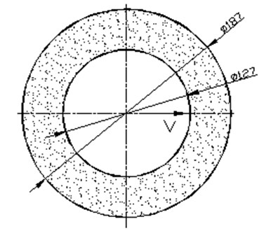
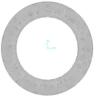
The two-dimensional geometric model of drillstring in annular drilling fluid is shown in Fig. 2(a). The inner circle is drillstring, diameter 127 mm, the outer circle is shaft wall, diameter 187 mm and the annulus fills with drilling fluid, density 1150 kg/m3. Since the model is simple, there is no need to simplify it, we can directly generate the grid. We use the dynamic mesh technology, which generally uses the triangular mesh. The divided meshes are shown in Fig. 2(b).
Fig. 2Computing model and meshes
a) Geometric model
b) Divided meshes
3.2. Physical model
Under the incompressible assumption, a standard - turbulence model is selected for numerical simulation based on the turbulence governing equations. K-epsilon (-) turbulence model is the most common model used in Computational Fluid Dynamics (CFD) to simulate mean flow characteristics for turbulent flow conditions. It is a two-equation model that gives a general description of turbulence by means of two transport equations (PDEs). The original impetus for the K-epsilon model was to improve the mixing-length model, as well as to find an alternative to algebraically prescribing turbulent length scales in moderate to high complexity flows.[21]
The - turbulence model is a semi-empirical and semi-theoretical formula, and and are determined by the following equations:
Among them, is the turbulent kinetic energy term caused by the average velocity gradient. Its formula is written as:
In the formula, is the turbulent viscosity, and is the empirical constant.
in Eq. (21) and Eq. (22) is a term of turbulent kinetic energy generated by buoyancy, and its formula is as follows:
Among them, is the coefficient of thermal expansion, ; is the Plandtl number of energy turbulence, 0.85.
In Eq. (21), YM indicates the impact of turbulent fluctuating expansion on dissipative energy in compressible fluid. The formula is as follows:
Among them, is the Mach number of turbulence, ; is the sound velocity, .
For compressible flow, 0, 0.
and in Eq. (21) and Eq. (22) are turbulent Prandtl numbers corresponding to turbulent kinetic energy and dissipation rate; , , are empirical constants, and , are self-defined source terms, which can be ignored when the external energy does not exist.
According to the recommended values and experimental verification, the constant values of the model are respectively 1.44, 1.92, 0.09, 1.0, 1.3.
3.3. Boundary condition setting
The boundary conditions of the calculation model of drillstring lateral vibration influenced by annular drilling fluid are set as follows. The annular part is set as a deformable fluid area and the drillstring motion equation is . In the formula, is the amplitude and is the angular frequency. The vibration velocity of drillstring is imported into FLUENT by UDF programming. The standard - turbulence model is selected to simulate the unsteady transient flow, and the grid is set as a moving grid. By changing the parameters of the motion equation, the motion of three different cases was simulated. The cases are amplitude 5 mm and frequency 1.5 Hz, amplitude 10 mm and frequency 2 Hz, amplitude 15 mm and frequency 1.5 Hz, respectively.
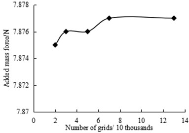
Fig. 3Added mass force for different grid numbers at 1.25 s
3.4. Verification of grid independence
In order to verify the independence of the grid, on condition that the amplitude is 5 mm and the frequency is 1 Hz, the simulation of 20000, 30000, 50000, 70000 and 130000 grids is carried out respectively. Fig. 3 shows the added mass force for different grid numbers at 1.25 s.
As can be seen from Fig. 3, when the number of grids changes from 20 thousands to 130 thousands, the value of added mass force changes little with the increase of the number of grids. It can be considered that when the number of grids is 70000, the simulation result is independent of the grid, so 70000 grids are taken as the calculation grid.
3.5. Analysis of calculation results
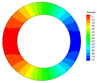
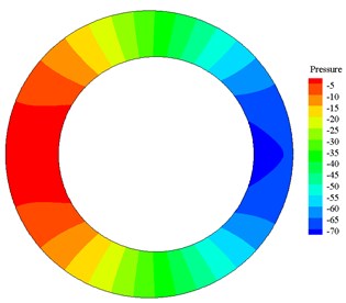
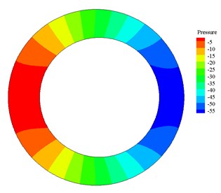
After calculation, when amplitude is 5 mm, frequency is 1 Hz, the pressure contours and velocity vector plots at 1.18 s, 1.25 s, 1.32 s and 1.37 s are shown in Fig. 4 and Fig. 5.
Fig. 4Pressure distribution contour at different time
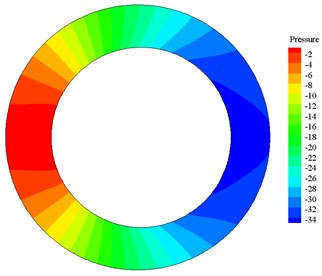
a) Pressure distribution at 1.18 s
b) Pressure distribution at 1.25 s
c) Pressure distribution at 1.32 s
d) Pressure distribution at 1.37 s
Pressure distribution contours in Fig. 4 and velocity vector plots in Fig. 5 correspond to each other. In Fig. 4 and Fig. 5, from (a) to (b) the high-pressure area on the left side becomes wider, the pressure increases, the velocity decreases and is positive (the right is positive direction). According to the motion equation, the acceleration is negative, and the magnitude of acceleration increases continuously, so from (a) to (b) drillstring decelerates to the right. When motion time of drillstring reaches 1.25 s, the pressure reaches the maximum, the acceleration reaches the maximum and the velocity is 0. From (b) to (c) and then to (d), the high-pressure zone on the left side narrows, the pressure decreases, the velocity increases and is negative (the left is in negative direction). According to the equation of motion, the acceleration is negative and the acceleration decreases, so the drillstring accelerates to the left. It shows that the pressure produced by the flow impedes the movement of the drillstring, which is the added mass effect.
By reading out the force on the drillstring, the added mass coefficient can be obtained as shown in tables 1, 2 and 3. As can be seen from Tables 1, 2 and 3, the added mass coefficient of drillstring lateral vibration is independent of amplitude and frequency, and the error between the simulation results and theoretical calculation results is small, which meets the needs of engineering calculation.
Fig. 5Velocity vector plot at different time
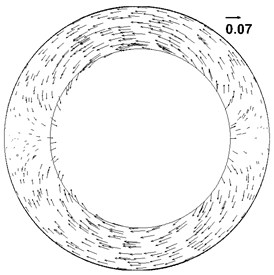
a) Velocity vector plot at 1.18 s
b) Velocity vector plot at 1.25 s
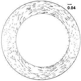
c) Velocity vector plot at 1.32 s
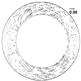
d) Velocity vector plot at 1.37 s
Table 1Added mass coefficient calculation results in case of amplitude 5mm, frequency 1 Hz
Time / s | Added mass force / N | Added mass force coefficient | Error |
1.18 | –7.00 | 2.69 | 0.78 % |
1.25 | –7.877 | 2.74 | 0.98 % |
1.32 | –7.204 | 2.77 | 2.04 % |
1.37 | –5.860 | 2.80 | 2.98 % |
Table 2Added mass coefficient calculation results in case of amplitude 15 mm, frequency 1.5 Hz
Time / s | Added mass force / N | Added mass force coefficient | Error |
0.084 | 36.246 | 2.62 | 3.34 % |
1.111 | 46.638 | 2.78 | 2.30 % |
1.223 | 47.999 | 2.87 | 5.42 % |
1.25 | 38.248 | 2.79 | 2.67 % |
Table 3Added mass coefficient calculation results in case of amplitude 10 mm, frequency 2 Hz
Time / s | Added mass force / N | Added mass force coefficient | Error |
0.565 | –43.349 | 2.59 | 4.92 % |
0.625 | –65.009 | 2.83 | 4.02 % |
0.815 | 43.522 | 2.60 | 4.50 % |
0.875 | 65.06 | 2.83 | 4.10 % |
3.6. Relevant verification of internal liquid influence on lateral vibration
Under the condition that only pipe interior is filled with drill fluid, we use the hammer strike experiments ware conducted of pipe outer diameter of 20 mm, 27 mm and 29 mm, the pipe instinct frequency was obtained. The interior mass additional coefficient of each outer diameter was computed, and instinct frequency was calculated through simulation taking its mass effect into consideration. Experimental measurement and simulation results are shown in Table 4.
As can be seen in Table 4, as the external diameter increases, the frequency increases. The simulation results are in good agreement with the test results, and the error is within 2%. Therefore, this method correctness has not been verified. We using CFD method and dynamic mesh technology, the pressure distribution and velocity distribution of annular drilling fluid are obtained, and the added mass force of drilling fluid acting on drillstring along the direction of drillstring motion is calculated from the pressure distribution, thus the added mass coefficient of drillstring lateral vibration is obtained.
Table 41st order natural frequency of drillstring when the interior is full of liquid
Outer diameter | Simulation frequency (Hz) | Experimental frequency (Hz) | Relative error | Internal additive mass coefficient |
20 mm | 46.42 | 45.52 | 1.98 % | 0.23 |
27 mm | 63.43 | 62.62 | 1.30 % | 0.20 |
29 mm | 68.60 | 69.35 | 1.08 % | 0.22 |
4. Conclusions
1) Based on the assumption of incompressible fluid, in the case of drilling fluid axial flow, the added mass coefficient of the annular drilling fluid’s influence on the lateral vibration of the drillstring is derived in this paper.
2) Considering the difficulty of calculating the added mass factor in case of the axial flow of drilling fluid, we use CFD method and dynamic mesh technology to simulate the annular flow caused by the vibration of drillstring in the annular drilling fluid under two-dimensional conditions. The added mass coefficient of drillstring lateral vibration is obtained. The error between the simulation results and theoretical calculation results is small, which meets the needs of engineering calculation.
3) According to the pressure and velocity distribution of annular drilling fluid obtained by simulation, when the pressure reaches the maximum, the velocity decreases to 0, and the drillstring decelerates to the right; when the pressure decreases, the velocity increases and the drillstring accelerates to the left. Fluid pressure creates added mass effect on drillstring.
References
-
Ritto T. G., Escalante M. R., Sampaio R., Rosales M. B. Drill-string horizontal dynamics with uncertainty on the frictional force. Journal of Sound and Vibration, Vol. 332, Issue 1, 2013, p. 145-153.
-
Xue Qilong, Leung Henry, Huang Leilei, et al. Modeling of torsional oscillation of drillstring dynamics. Nonlinear Dynamics, Vol. 96, Issues 1, 2019, p. 267-283.
-
Ren Fushen, Wang Baojin, Chen Suli, Yao Zhigang, Bai Baojun Nonlinear model and qualitative analysis for coupled axial/torsional vibrations of drill string. Shock and Vibration, Vol. 2016, 2016, p. 1646814.
-
Mitchell R. F., Allen M. B. Lateral vibration: the key to BHA failure analysis. World Oil, Vol. 200, Issue 4, 1985, p. 101-106.
-
Elsayed M. A., Phung C. C. Modeling of drillstrings. Proceedings of the 24th ASME International Conference on Offshore Mechanics and Arctic Engineering, Halkidiki, Greece, 2005.
-
Aadnoy B. S., Fazaelizadeh M., Hareland G. A 3D analytical model for wellbore friction. Journal of Canadian Petroleum Technology, Vol. 49, Issue 10, 2010, p. 25-36.
-
Wolf S. F., Zacksenhouse M., Arian A. Field measurements of downhole drillstring vibrations. SPE Annual Technical Conference and Exhibition, Society of Petroleum Engineers, Nevada, 1985, p. 22-26.
-
Alley S. D., Sutherland G. B. The use of real-time downhole shock measurements to improve BHA component reliability. SPE Annual Technical Conference and Exhibition, Dallas, Texas, 1991.
-
Batchelor G. K. An Introduction to Fluid Dynamics. Cambridge University Press, Cambridge, 1967.
-
Xue Qilong, Wang Ruihe, Sun Feng, Huang Zhiyuan Chaotic vibration analysis of the bottom rotating drillstring. Shock and Vibration, Vol. 2014, 2014, p. 429164.
-
Xue Qilong, Henry L., Wang Ruihe, Liu Baolin, Huang Leilei, Guo Shenglai The chaotic dynamics of drilling. Nonlinear Dynamics, Vol. 3, Issue 83, 2016, p. 2003-2018.
-
Khulief Y. A., Al Naser H. Finite element dynamic analysis of drillstrings. Finite Elements in Analysis and Design, Vol. 41, Issue 13, 2005, p. 1270-1288.
-
Sampaio R., Piovan M. T., VeneroLozano G. Coupled axial/torsional vibrations of drill-strings by means of non-linear model. Mechanics Research Communications, Vol. 34, Issue 5, 2007, p. 497-502.
-
Kapitaniak M., Hamaneh V. V., Chávez J. P., et al. Unveiling complexity of drill-string vibrations: Experiments and modelling. International Journal of Mechanical Sciences, Vols. 101-102, 2015, p. 324-337.
-
Sunit K., Gupta N., Pankaj Wahi Global axial-torsional dynamics during rotary drilling. Journal of Sound and Vibration, Vol. 375, Issue 4, 2016, p. 332-352.
-
Brebbia C. A., Wrobel L. C. Boundary element method for fluid flow. Advances in Water Resources, Vol. 2, 1979, p. 83-89.
-
Sarpkaya T. Vortex-induced oscillations: a selective review. Journal of Applied Mechanics, Vol. 46, Issue 2, 1979, p. 241.
-
Sarpkaya T. A critical review of the intrinsic nature of vortex-induced vibrations. Journal of Fluids and Structures, Vol. 19, Issue 4, 2004, p. 389-447.
-
Piero Villaggio The added mass of a deformable cylinder moving in a liquid. Continuum Mechanics and Thermodynamics, Vol. 8, Issue 2, 1996, p. 115-120.
-
Heisig G., Neubert M. Lateral drillstring vibrations in extended-reach wells. IADC/SPE Drilling Conference, New Orleans, Louisiana, 2000.
-
Larsson I. A. S., Lindmark E. M., Lundström T. S., Nathan J. G. Secondary flow in semi circular ducts. Journal of Fluids Engineering, Vol. 133, 2011, p. 101206-101214.
About this article

This study was funded by Natural Science Foundation of China (51704264), National Project “R&D of Key Tools and Equipment for Accelerating Drilling Speed and Efficiency in Complex Formations” (No. 2016ZX05021-003).
