Abstract
Tubing string is one of the most important tools in flowing production. In the state of lateral vibration instability of the tubing string, severe collisions between the string and casing may lead to tubing string failure and borehole wall sloughing. Stability of the tubing string is a potential safety hazard in the process of oil and gas production and discussed in this paper. Considering interaction among the gravity, internal fluid hydrodynamic force, reservoir pressure and liquid cushion in the annular, a mechanical model of lateral vibration of the tubing string, which is simplified as a uniform pipe conveying fluid upwards in vertical well, is developed, and the stability of the system is analyzed by the finite element method. The influences of the flow velocity, the bottom hole pressure and the height and density of liquid cushion on the stabilities of tubing string are discussed. It is found that the increase of either the flow velocity or the bottom hole pressure can cause the buckling of tubing string, however, increasing the height or density of liquid cushion is helpful to improve the stability of tubing string.
1. Introduction
Flowing production that oil is lifted to ground through tubing string by the energy of the reservoir itself, is an oil recovery technique. The stability of tubing string is closely related to the safe production of oil and gas. Under the interaction of the oil and string, lateral vibration instability of the string is prone to occur, and collisions between tubing string and casing would happen as a result. In severe cases, the tubing string breaks and falls off [1-3].
Tubing string has a wide range of applications in petroleum industry, such as well testing, fracturing, production and so on. The static analyses of the tubing string under different conditions were carried out by a few researchers over the past years. Considering the fluid property, internal and external fluid pressure, tubing temperature and the packer, mechanical models of the tubing string in whole testing and fracturing operation were established and solved by Li [4-6]. Cao et al. [7] analyzed the influences of the outer diameter and the length of joint on the critical buckling load of practical tubing string in vertical well based on the transfer matrix method. Mitchell [8] treated the casing string as elastomer rather than rigid body and proposed a computational method of contact forces between tubing string and casing string.
The research on the dynamics of tubing string is relatively few. Cai [1] regarded the additional dynamic load caused by unsteady flow as one of the main reasons resulting in the tubing string fatigue rupture in the process of production and established the motion equation of vertical vibration of tubing string. Li [2] studied preliminarily the dynamic characteristics of the tubing string for mining of oil/gas storage caverns without considering space constraint, and the critical velocity of the internal fluid in an ideal condition was obtained. Meanwhile considering space constraint, advice on the all-sided analysis of the tubing string dynamic characteristics was proposed. Taking into account the weight of the tubing string, the packer constraints, pre-stressing and the fluid pressure force, Yang [3] established a tubing string vibration equation. In these models, the effect of the external fluid is not considered.
The tubing string, which is confined in the casing, can be seen as a pipe conveying fluid upwards. A great deal of work about the pipe conveying fluid is done by Paidoussis and his cooperators. In 1978, Hannoyer and Paidoussis [9] analyzed the lateral vibration of the vertical cantilever tubular beam simultaneously subjected to independent internal and external flows, and the theoretical results of the dynamic behavior agreed with the experimental results well. In 2008, Paidoussis et al. [10] studied dynamics of a long tubular cantilever conveying fluid downwards, which then flowed upwards in the annular space through the lower end. It was found that the dynamics was dominated by the internal flow for the wide annular space, however, the annular flow was dominant for the narrow annular space. In 2016, the theoretical model of lateral vibration of a partially confined, discharging, and cantilever pipe with reverse external flow were developed and the corresponding experimental devices were set up. Results showed that an increase in these parameters, such as annulus diameter and confined-flow length, gave rise to flutter for short systems, or a succession of flutter and divergence for long systems [11]. In addition, Cesari and Curioni [12] investigated theoretically the static stability of horizontal tubular beams subjected to concurrent internal and external flows for various end conditions. Qian et al. [13] discussed the vibration and stability of upward-fluid-conveying pipe within a rigid cylindrical channel, where fluid flowed downwards.
Compared with the researches mentioned above, the tubing string in flowing production has its own characteristics, such as: 1) the external fluid is static; 2) only a part of the annulus between tubing string and casing is filled with fluid; 3) there is no correlation between the fluid inside and outside the pipe. And research on the lateral vibration of tubing string is limited. So, it is particularly important to study the dynamic characteristics of the tubing string to ensure the safe production of oil and gas.
In this paper, the lateral vibration stability of the tubing string applied in flowing production is analyzed. The tubing string is simplified as a uniform upward-fluid-conveying pipe with a fixed hinge at the wellhead and a movable hinge at the lower end. Considering the gravity, internal fluid hydrodynamic force, reservoir pressure and liquid cushion in the annular, the lateral vibration model of tubing string is established and solved by the finite element method. The effects of internal fluid velocity, the density and height of liquid cushion and reservoir pressure on the stability of the tubing string are discussed.
The organization of the paper is as follows: Firstly, the pseudo single-phase processing approach of the oil is introduced in Section 2. In Section 3, a theoretical model of lateral vibration of tubing string is derived and solved. Then, the effects of some key parameters on stability of tubing string are discussed in Section 4. Finally, concluding remarks are given.
2. Pseudo single-phase processing of the oil
Petroleum is a liquid mixture consisting mainly of hydrocarbons. In general, crude oil extracted from the reservoir contains water and gas as well as oil. The flow state of the three-phase mixture in the tube is very complicated. In order to simplify the analysis, the mixture in the process of oil production is considered as a pseudo single-phase fluid in this paper.
The pseudo single-phase fluid, whose characteristic parameters were equivalent to those of the two-phase flow of gas and liquid based on mass conservation, was proposed by Hoffman [14]. Montoya-Hernández [15]applied this method to treat a three-phase mixture of oil-gas-water as a pseudo single-phase and studied thenatural frequency of a marine riser. The theoretical results were in good agreement with the experimental results.
Here the density , velocity and viscosity of pseudo single phase fluid in the tube are expressed as:
where subscripts , and represent oil, gas and water phases, respectively. In the following sections, all the fluid parameters denote pseudo single-phase parameters.
3. Theoretical model
3.1. Derivation of theoretical model
The crude oil flows upward through a tubing string from the oil layer during oil recovery process. The upper end of the tubing string is connected with the tubing hanger, and the lower end is connected with the bayonet-tube packer. A certain height of liquid cushion is added into annulus between tubing string and casing, so that the pressure difference between the upper and lower ends of bayonet-tube packer is within safe range.
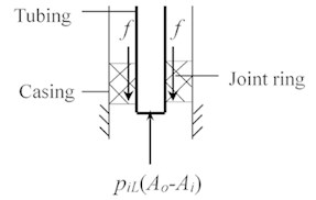
The tubing string in a vertical well is considered here. The string is simplified to be a uniform fluid-conveying pipe constrained by the fixed hinge at the wellhead and the movable hinge at the bayonet-tube packer that only limits the lateral displacement of the string, as shown in Fig. 1. The coordinate origin is located at the wellhead, and the -axis coincides with the axis of the undeformed tube string. is the lateral displacement, where is time. is the tubing string length, is the liquid cushion height, and is the internal fluid velocity. , which is the axial force exerted at the bottom of the tubing string (see Fig. 2), could be described as , in which is the fluid pressure at the bottom hole, i.e. reservoir pressure. and are external and internal cross-sectional area of tubing string, respectively, and is the friction between the tubing and joint ring.
For the annulus which is not filled with cushion, the liquid cushion density 0 and the viscous damping coefficient of the liquid cushion 0. By adopting the Heaviside step function , the density and damping coefficient of liquid cushion are expressed as and for the whole tubing string, respectively. Based on the theoretical model proposed by Paidoussis [9-11] and Qi [13], the lateral vibration equation of the tubing string is obtained:
The associated boundary conditions are:
where and are flexural rigidity and mass per unit length of pipe, respectively. is mass per unit length of internal fluid, , where is internalfluid density. is the velocity of internal fluid. is added mass coefficient due to the effect of confinement of annulus fluid, , where and is the inner diameter of casing and the outer diameter of tubing, respectively. is fluid pressure of liquid cushion at the bottom hole. is the hydraulic diameter, for the annulus channel flow. is related to the circular frequency of tubing string oscillation and shown as , where is the kinematic viscosity of the liquid cushion.
Fig. 1The sketch of tubing string
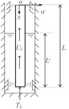
Fig. 2Force diagram at the bottom of tubing string
For convenience, the following dimensionless quantities are introduced:
The non-dimensional form of lateral vibration equation of tubing string is:
Associated with non-dimensional boundary conditions:
There is no relationship between the internal and external pressure in the bottom hole. The internal pressure is chosen as the reservoir pressure and the external pressure is calculated according to the hydrostatic pressure of the liquid cushion, approximately.
3.2. Discretization and solution
The governing Eq. (7) of lateral vibration of tubing string contains the Heaviside step function, which is a discontinuous function, and the finite element method is used here to discretize this system into an ordinary differential equation. The tubing string is divided into units. Taking the Hermite polynomial as shape function and substituting into Eq. (7), we could obtain the equation of motion of the th element:
where , and are mass matrix, damping matrix and stiffness matrix of the th element, respectively. They are:
Assembling the element matrices in the global coordinate system and taking the boundary conditions into account, the element equation of the whole tubing string is obtained:
where , and are all global matrices of order 2 corresponding to mass, damping and stiffness, respectively.
The approximate solution of Eq. (11) is expressed as:
where is an undetermined function of amplitude; is a dimensionless complex frequency. Submitting Eq. (12) into (11) yields:
To obtain a non-trivial solution of Eq. (13), it is required that the determinant of coefficient matrix is equal to zero. It corresponds to a generalized eigenvalue problem, and the stability of the system can be determined by the generalized eigenvalue of matrix that is composed of , and , as follows:
when the generalized eigenvalue satisfies 0 and 0, flutter occurs; when 0, bucking happens. With this method, the effects of parameters such as internal fluid flow, the density and height of liquid cushion and reservoir pressure on the stability of the tubing string are analyzed.
3.3. Model and algorithm validation
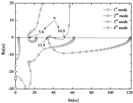
The developed model and numerical procedure are verified by comparison with the results of Gregory [16] in which the stability of lateral vibration of the tubular cantilevers conveying fluid downwards, was studied. The presented model degenerates to that proposed by Gregory by setting 0.2, 0, 1, and , and specifying the boundary conditions according to cantilever. What needs to be explained is that the complex frequency (generalized eigenvalue) defined in this paper is different from that in the reference [16]. Denoting complex frequency in the reference [16] as the relationship between them is: , and . The variations of the dimensionless complex frequency of the lowest four modes of the cantilevered system, which are functions of the dimensionless flow velocity and shown in Fig. 3, are in agreement with the results of Gregory. When the flow velocity 5.6 and 13.4, the real parts of the second and fourth modes become positive from negative, respectively, and flutter occurs. Comparing with the critical dimensionless flow rate 5.6 and 13.6 in the reference [16], the relative errors are 0 and 1.5 %, respectively. The correctness of the present model and algorithm is verified.
Fig. 3The dimensionless complex frequency of the lowest four modes of the cantilevered system as a function of the dimensionless flow velocity
4. Dynamics stability of tubing string
The dynamic stability of the tubing string with length 1000 m, inner diameter 0.062 m, outer dimeter 0.073 m, and mass per unit length 9.52 kg/m is studied here. The density and velocity of internal fluid are 800 kg/m3 and 2 m/s, respectively. The density and height of liquid cushion are 1600 kg/m3 and 1000 m, respectively. Bottom hole pressure 15.9 MPa, and the inner diameter of casing is 0.1273 m.
4.1. The effect of flow rate and bottom hole pressure
The first two modes of the generalized eigenvalue are obtained for different flow rate by solving Eq. (14) and shown in Fig. 4. With the increasing of flow rate, the real parts of the generalized eigenvalue increase and the imaginary parts of that decrease. It means that the stability of system is reduced. When the velocity of internal fluid reaches 2.205 m/s, the imaginary part of the first mode of generalized eigenvalue equals to zero, and buckling occurs.
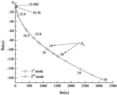
The first two modes of the generalized eigenvalue for different bottom hole pressure is shown in Fig. 5. With the increasing of bottom hole pressure, the real parts of generalized eigenvalue increase, and the imaginary parts decrease. When the bottom hole pressure are 15.902 MPa and 16.36 MPa, the imaginary part of the first and second modes of the generalized eigenvalue equals to zero, respectively. So, the system is in the state of buckling instability. The critical bottom hole pressure of the first and second modes are 15.902 MPa and 16.36 MPa, respectively. That is to say, increasing the fluid velocity or the bottom hole pressure, the stability of the system is reduced.
Fig. 4The first two modes of the generalized eigenvalue vs. flow rate
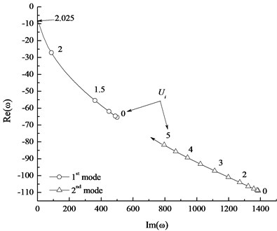
Fig. 5The first two modes of the generalized eigenvalue vs. bottom hole pressure
4.2. The effect of liquid cushion
The effects of the density and height of the liquid cushion on the stability of tubing string are shown in Fig. 6 and Fig. 7, respectively.
Fig. 6The first two modes of the generalized eigenvalue vs. liquid cushion density
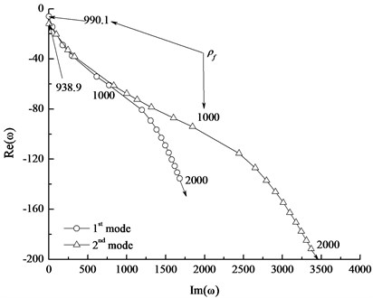
Fig. 7The first two modes of the generalized eigenvalue vs. liquid cushion height
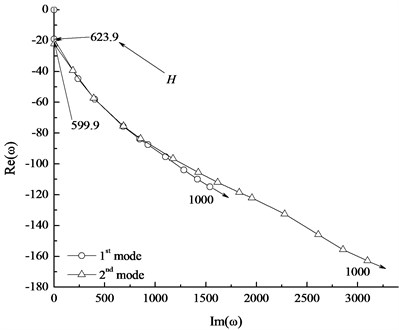
Fig. 6 presents that the imaginary parts of the first-mode and second-mode eigenvalues are all positive when the density is more than 990.1 kg/m3. The system converts from buckling state to stable state as the density varies from 0 to 990.1 kg/m3. This density is the critical density of liquid cushion. With the further increase of the liquid cushion density, the imaginary part of the generalized eigenvalue increases and the real part decreases, so the stability of tubing string increases. The influence of the liquid cushion height on the system is similar to that of the liquid cushion density, as shown in Fig. 7. With the increase of the liquid cushion height, the system converts from buckling instability into steady state, and the critical height is 623.9 m.
4.3. Stable region in the cushion height – cushion density plane
From the above analysis we can see that the stability of the tubing string can be improved by increasing height or density of the liquid cushion. The stable region in the parameter plane consisting of the liquid cushion height () and the liquid cushion density () is shown in Fig. 8. The critical density of the cushion reduces almost hyperbolically with the increase of liquid cushion height.
Fig. 8The effect of tubing string length on the stable region in the cushion height - cushion density (H-ρf) plane
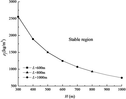
The influence of the tubing string length on the stable region is shown in - plane and presented in Fig. 8. For the same liquid cushion height, the critical density of liquid cushion is almost the same with the variations of tubing string length. It is found that the influences of the internal fluid density and the inner diameter of casing on the stable region are the same as that of the tubing string by solving Eq. (14). In other words, these three parameters have no effect on the stable region in the - plane, and the effects of the three parameters on the stability of tubing string system can be ignored.
Fig. 9The effect of bottom hole pressure on the stable region
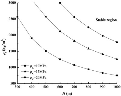
Fig. 10The effect of friction provided by packer on the stable region
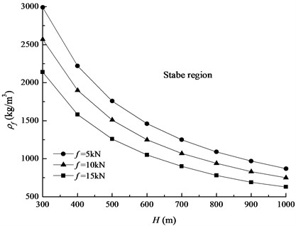
The equivalent axial force at the bottom of tubing string, denoted as , is determined by the bottom hole pressure and the frictional resistance provided by the bayonet-tube packer. The influence of on the stable region is shown in Fig. 9. It is found that the critical - curve moves towards the right and upwards along with the bottom hole pressure increasing. It means that the stable region decreases and the stability of the system reduces. Because the frictional resistance of bayonet-tube packer reduces the equivalent axial force of the bottom of tubing string, larger fractional force is beneficial to the stability of the system, as shown in Fig. 10.
5. Conclusions
Tubing string used in oil production is simplified as a uniform upward-fluid-conveying pipe with a fixed hinge at the upper end and a moveable hinge at the lower end. The numerical model of transverse vibration of tubing string is developed and the stability of the system is discussed. The following conclusions are obtained:
1) The flow velocity and the bottom hole pressure are the driving forces of the instability of tubing string, and the increase of either the flow velocity or the bottom hole pressure can cause the buckling of tubing string.
2) Increasing the height and density of liquid cushion is helpful to improve the stability of tubing string.
3) Parameters such as the tubing string length, the internal fluid density and the inner diameter of casing have almost no influence on the stability of the system, while either increasing the bottom hole pressure or reducing the friction provided by packer is harmful to the stability of the system.
In the course of flowing production, adding liquid cushion in the annulus can not only ensure the packer within the safe working pressure difference, but also improve the stability of the tubing string. Meanwhile, the stability of system can also be improved by increasing the friction force between tubing and joint ring.
References
-
Cai Y. X., Li Q., Huang Z. Tubing string solid-liquid coupling vibration analysis. Natural Gas Industry, Vol. 18, Issue 3, 1998, p. 54-56.
-
Li Y. P., Yang C. H., Qu D. A., et al. Preliminary study of dynamic characteristics of tubing string solution mining of oil/gas storage salt caverns. Rock and Soil Mechanics, Vol. 33, Issue 3, 2012, p. 681-686.
-
Yang M., Ma Y., Li S. G. Vibration characteristics analysis of tubing string in three-high gas well. Advanced Materials Research, Vol. 455, Issue 456, 2012, p. 395-399.
-
Li Z. F. Mechanic analysis of tubing string in well testing operation. Journal of Petroleum Science and Engineering, Vol. 90, Issue 91, 2012, p. 61-69.
-
Li Z. F., Sun H., Su J. Z., et al. Theory and applications of mechanical analysis of tubing string in fracturing operation. Journal of Basic Science and Engineering, Vol. 20, Issue 5, 2012, p. 846-862.
-
Li J. Y., Li Z. F. Mechanical analysis of tubing string in fracturing operation. Open Petroleum Engineering Journal, Vol. 6, Issue 1, 2013, p. 12-24.
-
Cao Y. P., Xia H., Dou Y. H. Stability of tubing string in vertical based on transfer matrix method. Information Technology Journal, Vol. 12, Issue 21, 2013, p. 6263-6267.
-
Mitchell R. Buckling of tubing string inside casing. SPE Drilling and Completion, Vol. 27, Issue 4, 2012, p. 486-492.
-
Hannoyer M. J., Paidoussis M. P. Instabilities of tubular beams simultaneously subjected to internal and external axial flows. Journal of Mechanical Design, Vol. 100, Issue 2, 1978, p. 328-336.
-
Paidoussis M. P., Luu T. P., Prabhakar S. Dynamics of a long tubular cantilever conveying fluid downwards, which then flows upwards around the cantilever as a confined annular flow. Journal of Fluids and Structures, Vol. 24, Issue 1, 2008, p. 111-128.
-
Moditis K., Paidoussis M., Ratigan J. Dynamics of partially confined, discharging, cantilever pipe with reverse external flow. Journal of Fluids and Structures, Vol. 63, 2016, p. 120-139.
-
Cesari F., Curioni S. Buckling instability in tubes subjected to internal and external axial fluid flow. Proceeding of the 41 Conference on Dimensioning, Budapest, 1971.
-
Qian Q., Wang L., Ni Q. Vibration and stability of vertical upward-fluid-conveying pipe immersed in rigid cylindrical channel. Acta Mechanica Solida Sinica, Vol. 21, Issue 5, 2008, p. 431-440.
-
Hoffman K. A., Chiang S. T., Siddiqui S., et al. Fundamental equations of fluids mechanics. Engineering Education System, Wichita, 1996.
-
Montoya Hernández D.-J., Vázquez Hernández A.-O., Cuamatzi R., et al. Natural frequency analysis of a marine riser considering multiphase internal flow behavior. Ocean Engineering, Vol. 92, 2014, p. 103-113.
-
Gregory R. W., Paidoussis M. P. Unstable oscillation of tubular cantilevers conveying fluid. I. theory. Proceedings of the Royal Society A, Vol. 293, 1966, p. 512-527.
About this article

This project was supported by the National Natural Science Foundation (51134004, 11102173).
