Abstract
A new single-degree-of-freedom quadruped robot leg walking mechanism is proposed to solve the problems of more drive elements, more complex structure and control system in existing single-leg walking mechanism. The principle scheme and structure design of the leg walking mechanism of the quadruped robot are completed according to the requirements of the foot end trajectory curve and the actual motion characteristics. The dimensions of each rod of the single-leg crank rocker mechanism to meet the “inverted D-type” motion law at the E point on the linkage are solved by using the Burmester four-rod mechanism integrated graphical method. The kinematic equations at the P point of the foot end of the proposed scheme are derived by using the kinematic analysis. By ADAMS simulation, the displacement and velocity curves at the P point of the foot end can well meet the requirements of the foot end movement law. The present methodology can not only achieve the goal of less driving elements and more simple design in single-leg walking mechanism, and can well meet the requirements of walking stability and smoothness of motion.
1. Introduction
In recent years, legged robots have become a hot topic of research for domestic and foreign scholars, inspired by the strong terrain adaptation and good motion flexibility of legged mammals in nature. As a member of the legged robot family, quadruped robots have the characteristics of simple structure, good flexibility and stability, and strong adaptability to terrain compared with biped and other multiped robots. From the perspective of bionics, most mammals in nature have four legs, which shows that quadruped robots occupy an important position in legged robots [1].
At present, domestic and foreign scholars have carried out a lot of research on quadruped robots and achieved good results. Typical representatives are: Boston Dynamics’ BidDog [2] and SpotMini [3] quadruped robots, MIT's Cheetah [4] series quadruped robots, Zhejiang University’s electrical-driven quadruped robots “Jueying” [5] etc. The above robots can well achieve the expected design goals, but the movement of the leg mechanism is in the form of multi-drive and multi-control, and there are many power components, complex four-leg action coordination control system and high cost. In order to solve the above problems, the author proposes a single leg single drive, four legs isomorphic scheme, through the scale analysis to determine the size of each component of the constituent mechanism, the motion analysis and ADAMS simulation analysis to verify the movement flexibility and walking gait stability, to achieve the goal of less driving components, simple structure, easy to control, low cost, laying a foundation for its future application.
2. Theory of quadruped robot design
2.1. The proposed design scheme
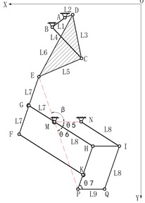
The quadruped robot mainly relies on the motion of the limbs to achieve the working goal, and the diverse control of limb motion can realize the robot’s movements such as straight travel, turning and climbing. In order to meet the requirements of minimal control elements, easy maintenance and simple structure, the design scheme of the same structure, independently driven and single-legged single degree of freedom is determined for all four limbs. Combined with the advantages of perfect design theory of planar four-bar mechanism, the single leg adopts crank rocker mechanism and scaling mechanism in tandem to realize the motion law of single leg. The overall structural scheme of the robot and the sketch of the single-leg walking mechanism are shown in Fig. 1 and Fig. 2.
Fig. 1Overall structure scheme
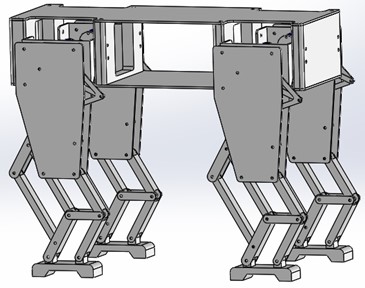
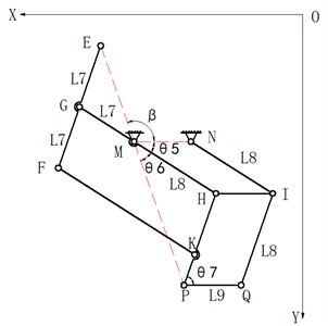
Fig. 2Schematic diagram of single leg walking mechanism
2.2. Analysis of the institutional structure of the proposed scheme
2.2.1. The foot trajectory curve
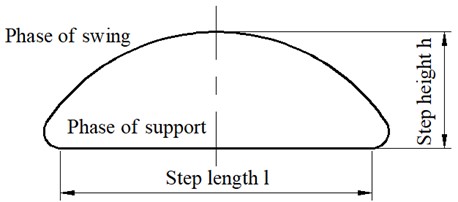
When designing the single-legged walking mechanism of the quadruped robot, it is first necessary to determine the appropriate trajectory curve of the foot end. To ensure the stability of the quadruped robot motion and terrain adaptation capability, the designed foot-end trajectory curve for single-legged robot walking is the “inverted D” curve shown in Fig. 3.
Fig. 3Ideal foot trajectory curve
2.2.2. Scale design of single leg crank rocker mechanism
In Fig. 2, the mechanism ABCDE is designed as a crank-rocker mechanism, where the rod AB is the frame, the rod AD is the input crank, the rod BC is the rocker, the rod CDE is the connecting rod. The motion trajectory of point E is the curve law shown in Fig. 3. The length of each component of mechanism ABCDE can be obtained from the Burmester four-bar mechanism comprehensive diagram method [6] according to the shape of the motion trajectory of point E.
To ensure step length and step height, the minimum rotational angle of the crank AD corresponding to the straight part of the trajectory at point E is not less than 180°. To ensure the mechanism has good force transmission performance, the minimum transmission angle of the mechanism is not less than 15°.
2.2.3. Design of single leg walking mechanism
In Fig. 2, the single-leg walking mechanism is composed of the crank-rocker mechanism ABCDE and the scaling mechanism EFHP. When the crank turns around, the movement of point E on the connecting rod is “inverted D” type. In order to improve the walking efficiency of the robot and realize the big step motion, a scaling mechanism EFHP is designed to enlarge the trajectory curve of point E.
The scaling mechanism EFHP is a four-link mechanism, in which GFKP is a parallelogram and points E, M and P are collinear, so the shape of the motion trajectory of point P is exactly the same as that of point E and is a proportional scaling of the trajectory of point E. The scaling ratio of the scaling mechanism is the ratio of the length of HM and GM, and different step length and step height can be obtained by adjusting the ratio.
In addition, two auxiliary parallelogram mechanisms MNIH and HIQP are added to the right side of the scaling mechanism EFHP. When the robot completes a large load task, the module is added to improve the force of the single-leg walking mechanism and improve the stability of the quadruped robot during walking.
2.3. Kinematic analysis of a single legged walking mechanism
As mentioned before, the four legs of the designed quadruped robot are the same, and the kinematic analysis of the robot can be carried out on only one leg.
2.3.1. The trajectory equation at point E
In the crank rocker mechanism ABCDE shown in Fig. 4, the inertial coordinate system is XOY, the local coordinate system is , the coordinates of point A are (, ), is the angle between the frame AB and the axis , is the angle between the crank AD and the axis , is the angle between the rocker BEand the axis , and the angle between the connecting rod DE and the axis is . The position of point E in XOY can be obtained from Eq. (1):
where , are the coordinate components of the local coordinate system . They can be expressed as:
where can be computed from:
where , , can be computed from:
The general arrangement is shown in Fig. 5. The relations among the lengths of all members are, and. The angle between the rod GH and MN is , the angle between the rod EP and MN is , the angle between the rod EP and GH is , and the angle between the rod HP and PQ is . The magnification ratio of the scaling mechanism is H. The coordinate components of point P in the coordinate system can be shown as:
where , are the coordinates of point P in the coordinate system .
Fig. 4Crank rocker mechanism ABCDE
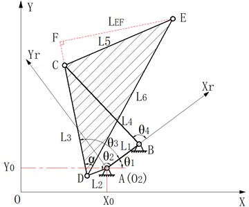
Fig. 5The scaling mechanism EFGHKP
3. ADAMS simulation example
In order to verify whether the proposed quadruped robot scheme can meet the requirements of “inverted D” type motion law and step size at point P, the reliable commercial software ADAMS was selected to complete the simulation of the mechanism. The required step length is 280 mm and the magnification ratio is 1.5.
According to the requirements of step length and amplification ratio, the dimensions of each component of the single-leg walking mechanism and the initial angle of frame AB determined by the theory proposed in this paper are as follows: = 52.46 mm, = 26.82 mm, = 203.91 mm, = 205.83 mm, = 196.91 mm, = 218.97 mm, = 100mm, = 150 mm, = 100 mm, and = 52.05°. The specific simulation process is as follows:
Step 1: According to the size of each member of the single-leg walking mechanism, the three-dimensional geometric model established by SolidWorks are shown in Fig. 6.
Step 2: The built 3D model is saved as the filename . , and then imported into ADAMS. The necessary constraints are added in the single-leg walking mechanism. A counterclockwise drive of 180d * time is imposed on the crank rotation pair of the single-leg walking mechanism, the simulation time is set as 6s and the number of steps is 1500.
Step 3: The red trajectory curve of the lowest point of the foot is shown in Fig. 6 by simulated analysis on ADAMS. The displacement curve and velocity curve of the foot's centroid along the and axes are shown in Fig. 7 and Fig. 8, respectively.
Fig. 6Solid model of single-leg mechanism
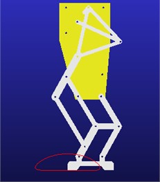
Fig. 7Displacement curves of the foot center of mass in the X and Z axes
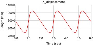
a) Displacement in the -axis direction
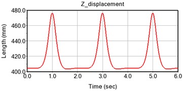
b) Displacement in the -axis direction
Fig. 8Velocity curves in X and Z directions of quadruped robot
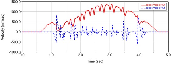
The simulation results show that the displacement and velocity curves change periodically, and the curves are smooth and continuous without abrupt changes. It can be seen from the displacement and velocity curve that the displacement in the -axis direction is approximately a straight line in the stage of foot support, and the corresponding velocity is almost zero. Therefore, the proposed mechanism has good motion stability. The foot displacement curve is the “inverted D” type. Its measured step length and step height are respectively 279.8 mm and 73 mm, thus the present mechanism has good stride walking ability and obstacle overcoming ability.
4. Conclusions
Based on the design concept of simple control, easy implementation and few driving components, a single-leg walking mechanism scheme of single-DOF quadruped robot is proposed, its scale design is completed, the foot displacement law is derived, and the simulation verification is carried out by ADAMS. The research conclusions are as follows: (1) The scheme of single leg walking mechanism with single degree of freedom and series of crank rocker mechanism and scaling mechanism is proposed, which achieves the goal of less driving components and simple design. (2) The “inverted D” walking gait trajectory is realized by using the four-bar mechanism in series, which reduces the degree of freedom of the leg mechanism of the quadruped robot. (3) The additional auxiliary mechanism can enhance the load-bearing ability of the robot and improve the stability of motion. The unique sole structure increases the contact area between the sole and the ground, reduces the load of each member of the mechanism, and lays a solid foundation for the lightweight design of the mechanism. (4) The analytical expression of the foot displacement of the quadruped robot is derived, which lays the foundation for the dynamic analysis. (5) The foot kinematics simulation of the designed single-leg walking mechanism is carried out by using ADAMS, and it is verified that the design scheme of the robot can well meet the requirements of motion law and motion stationarity. The simulation results indicate that the proposed single-leg mechanism scheme of the quadruped robot is feasible and reliable, and can effectively support the engineering practice.
References
-
W. Xu, T. Yan, P. Xu, and Z. J. Liang, “Quadruped Bionic Robot: the new cutting-edge of special robot industry,” Robot Industry, Vol. 39, No. 4, p. 50, 2021.
-
M. Raibert, K. Blankespoor, G. Nelson, and R. Playter, “Bigdog, the rough-terrain quadruped robot,” IFAC Proceedings Volumes, Vol. 41, No. 2, pp. 10822–10825, 2008, https://doi.org/10.3182/20080706-5-kr-1001.01833
-
Simone C. Niquille, “Regarding the pain of spotmini: Or what a robot’s struggle to learn reveals about the built environment,” Architectural Design, Vol. 89, No. 1, pp. 84–91, 2019.
-
G. Bledt, M. J. Powell, B. Katz, J. Di Carlo, P. M. Wensing, and S. Kim, “MIT Cheetah 3: Design and control of a robust, dynamic quadruped robot,” in International Conference on Intelligent Robots and Systems (IROS), pp. 2245–2252, Oct. 2018.
-
C. Li, “Planning and Control of Running and Jumping Motion of Quadruped Bionic Robot,” Zhejiang University, 2017.
-
J. P. Vidosic and D. Tesar, “Selection of four-bar mechanisms having required approximate straight-line outputs Part I. The general case of the ball-burmester point,” Journal of Mechanisms, Vol. 2, No. 1, pp. 23–44, Mar. 1967, https://doi.org/10.1016/0022-2569(67)90055-9
Cited by
About this article

The authors have not disclosed any funding.
The datasets generated during and/or analyzed during the current study are available from the corresponding author on reasonable request.
The authors declare that they have no conflict of interest.
