Abstract
In this paper, the 14-equations of pipeline system were written as matrix forms in frequency domain with Laplace transformation and further solved by transfer matrix method (TMM). Moreover, the added mass and added damping models were established and combined with the TMM for decoupling investigated the Turbulence-Induced Vibration (TIV) of clamped-clamped pipe system. Firstly, the feasibility of the TMM for analyzing the frequency responses of water-filled pipelines with free support boundary conditions and the added mass, added damping for decoupling investigation of TIV were finished verify. Then the frequency responses for Fluid-Structure Interaction (FSI) problems of pipeline with different flow velocities were acquired. The results indicate that the calculated frequencies agree well with corresponding data yield from Galerkin method. And the increasing flow velocity results in a decreased amplitudes of the frequency responses due to the effect of fluid added damping. Those results of the research in this paper implied that the decoupling method composed of the TMM that considered the added mass and added damping is validity and accuracy for frequency response analysis of the pipeline.
Highlights
- A semi-numerical simulation method is concerned with the development of a unidirectional decoupling investigation of the bidirectional Fluid Structure Interaction (FSI) problem by combining the TMM with the added mass, added damping analogy model.
- The feasibility of the TMM combine with the decoupling method was finished verify by comparing the calculated frequencies with data yield from Galerkin method.
- Physical insight into the relationship between the frequency response of the pipe vibration and the velocity of turbulent fluid is analyzed by TMM and the decoupling method.
1. Introduction
As we all know, pipeline systems are widely applied in all kinds of working conditions and the Fluid-Induced Vibration (FIV) problems of pipe systems have been investigated extensively by theory approach, FSI simulations and experiments in resent year. Since the bending vibration of a pipe is similar with the beam, the Euler-Bernoulli beam and Timoshenko beam can be used to establish the FIV model when the pipe systems with large slenderness ratio. Moreover, the 14-equations can be presented base on simplified models and written into frequency domain, further combine with transfer matrix method (TMM) to yield the vibration characteristics and frequency responses for conservative or non-conservative systems, linear or nonlinear problem [1].
But the results calculated from the traditional theoretical methods may be unreliable under the effect of perturbation turbulence flow. Fortunately, the turbulent fluid force can be transformed to added mass and added damping to finishing decoupling investigation of the FIV problem [2]. Furthermore, the stability and vibration response of Fluid-Structure Interaction (FSI) system with increasing flow velocity can be investigated. It is known from previous studies that the fluid added mass and damping on still or uniform flow can be calculated by finite element method (FEM) [3] or FIV numerical simulation [4]. However, limited efforts are focused on obtaining the added mass and damping for the FIV systems with high velocity turbulence flow. Therefore, it is worthy to establish a decoupling method for computing the turbulent fluid added mass and damping of shell FIV systems, and then analyzing the vibration frequencies and time or frequency responses by combining the TMM and added mass, added damping analogy method.
2. Theoretical methods
2.1. FIV model of shell structure
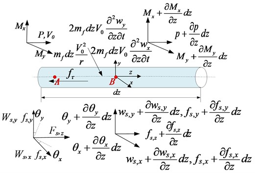
In the present works, a straight pipeline is applied for investigating the vibration frequencies and time or frequency responses of the FIV system. In addition, the compressible and viscosity turbulent flow was employed to finish our works, and the FIV system in present work was unidirectional that the radial deformation of shell vibration on the fluid was neglected. Therefore, the FIV model of pipeline structure with the effect of fluid forces are displayed in Fig. 1.
Furthermore, the 14-equations in time domain can be established based on Fig. 1 and the theoretical method in literature [5]. As shown in Eq. (1), the 14-equations can further be written as matrix forms in frequency domain with Laplace transformation:
The variables , and in Eq. (1) are reported as follow:
And the coefficients , , , , , , and the matrices , and are explained [5].
The parameters in Eq. (1) and (2) are listed in the nomenclature. Furthermore, the solution of Eq. (1) can be described as:
The matrices , , , and are given by reference [5]. Ultimately, for section, eliminating the unknown constants in Eq. (7) lead to:
where, 0 and are the beginning and end of any pipeline section. is the field transfer matrix and is defined as:
Fig. 1The model of straight pipeline
2.2. Boundary conditions
As shown in Fig. 2, the boundary conditions of pipeline are composed of linear elastic stiffness and flexural stiffness. Therefore, the clamped-clamped boundary conditions used in this paper may be acquired by the case of both the stiffness are approach to infinity. Moreover, the boundary conditions are written in the form of matrices to finish the analytical solution of TMM:
Fig. 2Boundary conditions of cylindrical shell, where kS,x0(l), kS,y0(l), kS,z0(l), kS,xL(l), kS,yL(l), and kS,zL(l) are linear elastic stiffness, kS,x0(t), kS,y0(t), kS,z0(t), kS,xL(t), kS,yL(t), and kS,zL(t) are torsional elastic stiffness, which forms the boundary conditions of cylindrical shell [2]
![Boundary conditions of cylindrical shell, where kS,x0(l), kS,y0(l), kS,z0(l), kS,xL(l), kS,yL(l), and kS,zL(l) are linear elastic stiffness, kS,x0(t), kS,y0(t), kS,z0(t), kS,xL(t), kS,yL(t), and kS,zL(t) are torsional elastic stiffness, which forms the boundary conditions of cylindrical shell [2]](https://static-01.extrica.com/articles/23347/23347-img2.jpg)
2.3. Added mass and damping model
As described in literature [2], the turbulent fluid added mass and added damping that including the effects of pressure coefficient, turbulent kinetic energy and the displacement of shell are established:
where, and are Fourier coefficients; is the coupling frequency of FIV system; is so-called turbulence coefficient; In addition, the experience added mass is employed for comparing results:
3. Validation of the added mass method and TMM
Based on our previous works [2], Fig. 3 reported the compared results of added mass, added damping and time history displacement for the case of shell vibrating in a NaFNaB fluid with variable velocity. From Fig. 3(a) and (b), we can see that the added mass has no significant relation with frequency, whereas the effect of frequency on added damping cannot be neglected. Moreover, the modal frequencies are decreased with flow velocity and the critical velocities may induce buckling instability. Ultimately, increasing the flow velocity may result in an increased added damping, both the added mass and damping may further affect the period and amplitudes of time history displacement of pipeline structure.
Furthermore, the frequency responses of FSI systems for the water-filled pipelines with free support boundary conditions was reported in Fig. (4). It is found that the results computed from the TMM are good agreement with the corresponding results in Ref [6], the little error may be induced by the ignored friction coupling. So that means the established TMM is validity and accuracy for FSI problems of liquid-filled pipelines and can be further applied to the decoupling method by including the added mass and damping.
Fig. 3The relationship of first three modal frequency, added damping and time history displacement with turbulent flow velocity
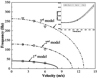
a) First three modal frequencies
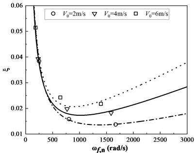
b) First three modal frequencies
c) Time history displacement
Fig. 4Frequency responses of FSI systems for the liquid-filled pipeline
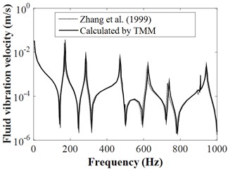
a) Axial fluid vibration velocity of shell
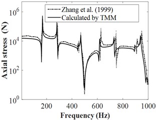
b) Axial stress of shell
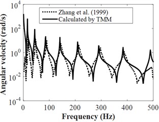
c) Angular velocity of pipe
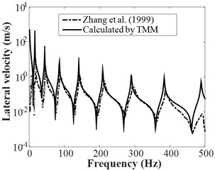
d) Lateral vibration velocity of pipe
4. Numerical examples and analysis
4.1. Computation model of the pipeline
In this paper, the straight pipeline that analysed in reference [7] was yielded for the further investigating the frequency response of FSI problems. Where the involved parameters of the FSI systems was reported in Table 1. On the other hand, the turbulent flow for the cases of 0 m/s, 50 m/s and 100 m/s conveyed fluid velocity are simulated by Large Eddy Simulation (LES) method, and further transformed the fluid effects into added mass and added damping. Finally, the beam188 elements with the clamped-clamped boundary conditions were employed for establishing the pipe model. Therefore, the FSI problems in frequency domain can be decoupling analysis by combining the TMM with turbulent flow added mass and added damping.
Table 1The geometrical and material properties of the analysis FSI systems
Steel pipe | Young’s modulus (GPa) | 96 | Manager (m) | 1 |
Poisson’s ratio | 0.39 | Thickness(m) | 1×10⁻³ | |
Density (kg.m-3) | 4470 | Out diameter (m) | 1.4×10⁻² | |
Water | Bulk modulus (GPa) | 1.3 | Density (kg.m-3) | 802.4 |
4.2. Added mass and natural frequency
In previous section 3, the validation of the added mass, added damping method and TMM are provided, those methods may be combined for further analysing the frequency response of the pipeline vibration induced by turbulent flow. As shown in Table 2, the calculated results in present works agree well with those acquired by Galerkin method. The importance of the present decoupling method is that the added mass, added damping, modal frequencies and vibration responses can be investigated simultaneously. Moreover, the added damping is sensitive to modal orders and increases with increasing flow velocity. And the critical velocity can further yield by fitting the results in Table 2, or compute by , where 146.8 m/s, 267.2 m/s, and 875.6 m/s. Actually, the flow rate in engine fuel line is much less than those critical velocity, therefore, the pipe will keep away from the buckling instability.
Table 2First three frequencies and added damping ratios for different flow velocity
Velocity | Method | 1st | 2nd | 3rd | |||
– | – | (Hz) | (%) | (Hz) | (%) | (Hz) | (%) |
0 m/s | Galerkin (2017) | 97.14 | – | 262.05 | – | 508.29 | – |
Calculation | 93.53 | – | 254.33 | – | 485.68 | – | |
50 m/s | Galerkin (2017) | 89.31 | – | 260.63 | – | – | – |
Calculation | 86.84 | 3.22 | 238.9 | 1.92 | 462.62 | 1.41 | |
100 m/s | Galerkin (2017) | 78 | – | 246.64 | – | – | – |
Calculation | 74.72 | 5.46 | 225.38 | 2.26 | 397.11 | 1.54 | |
Fig. 5Frequency responses of FSI systems for the liquid-filled pipeline
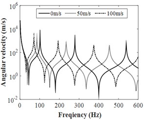
a) Angular velocity of pipe
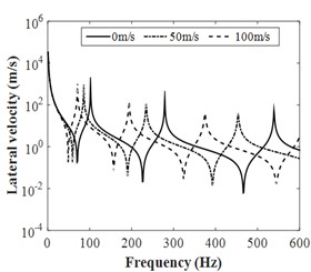
b) Lateral vibration velocity of pipe
4.3. Vibration response analysis
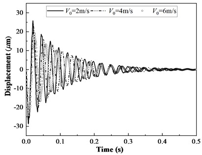
Based on the calculated added mass and added damping in previous section 3, the frequency responses of the clamped-clamped straight pipe with the influence of pulsating flow velocities were yield by TMM. A longitudinal impulsive force 80 kN and 2 ms was applied in the end of 0 to simulate the fluid force. The measure point B as shown in Fig. 1 was placed for monitoring the frequency responses of vibration pipe. Fig. 5 provide the lateral frequency responses of the clamped-clamped straight pipe, the lateral frequency results calculated by TMM including the added mass, added damping shown a good agreement with FEM results in Table 2. The little deviation may come from the ignored friction coupling or the difference of pipe modelling method, where the beam mode is applied in TMM. Moreover, the increasing flow velocity results in a decreased amplitudes of the frequency responses due to the effect of added damping. This means that the decoupling method by combining TMM with added mass and added damping has excellent accuracy for frequency response analysis of FSI pipe. Noting that the added mass and damping model are established bases on the transverse force balance condition, so that the present models may not be suitable for investigating the axial frequency response problems, the added mass and added damping for axial vibration may be calculated in the future.
5. Conclusions
In this paper, the frequency responses of Turbulence-Induced Vibration of clamped-clamped pipe system were analysed by combining TMM with the calculated added mass and added damping. The calculated frequencies agree well with corresponding data yield from Galerkin method. And the increasing flow velocity results in a decreased amplitudes of the frequency responses due to the effect of added damping. This implied that the decoupling method composed of the TMM that considered the added mass and added damping is validity and accuracy for frequency response analysis of the pipeline.
References
-
J. W. Miles, “Supersonic flutter of a cylindrical shell-II,” Journal of the Aerospace Sciences, Vol. 25, No. 2, pp. 312–316, 2015.
-
Y. Zhou, B. Xiao, S. Shi, C. Gao, and Z. Liu, “Analysis of turbulence-induced vibration of cylindrical shell based on added mass and added damping analogy,” Ocean Engineering, Vol. 271, p. 113768, Mar. 2023, https://doi.org/10.1016/j.oceaneng.2023.113768
-
Y. Zhou, Y. Li, Z. Yu, and A. Yoshida, “Study on added mass of a circular curved membrane vibrating in still air,” Thin-Walled Structures, Vol. 127, pp. 200–209, Jun. 2018, https://doi.org/10.1016/j.tws.2018.01.034
-
D. de Santis and A. Shams, “Scaling of added mass and added damping of cylindrical rods by means of FSI simulations,” Journal of Fluids and Structures, Vol. 88, pp. 241–256, Jul. 2019, https://doi.org/10.1016/j.jfluidstructs.2019.05.011
-
G. M. Liu, S. J. Li, Y. H. Li, and H. Chen, “Vibration analysis of pipelines with arbitrary branches by absorbing transfer matrix method,” Journal of Sound and Vibration, Vol. 332, No. 24, pp. 6519–6536, 2013.
-
L. Zhang, S. A. Tijsseling, and E. A. Vardy, “FSI analysis of liquid-filled pipes,” Journal of Sound and Vibration, Vol. 224, No. 1, pp. 69–99, Jul. 1999, https://doi.org/10.1006/jsvi.1999.2158
-
Z. Y. Li, J. J. Wang, and M. X. Qiu, “Natural Frequency Analysis of Fluid-structure Coupling Vibration of Aero-engine Pipeline,” Aeronautical Engine, Vol. 43, pp. 66–70, 2017.
About this article

This work was supported by National Natural Science Foundation of China (Grant Nos. 51475088 and 51705071) and Natural Science Foundation of Jilin Province of China (Grant Nos. 20230101318JC, 20230101319JC, 20190201109JC and 20190103058JH).
The datasets generated during and/or analyzed during the current study are available from the corresponding author on reasonable request.
The authors declare that they have no conflict of interest.
