Abstract
Pipeline is an important transportation facility in the oil and gas industries. But cracks inevitably appear in the pipe body due to various factors. Mechanical analysis of cracked pipe structures based on local flexibility has received increased attention in the last three decades. However, few reports exist on the local flexibility of pipes with an arbitrary angled crack. In this paper, the general solution of the local flexibility equations of a pipe with a part through-crack subjected to axial force, shearing force, and bending moment is deduced with respect to an arbitrary angled crack. The proposed equations consider the influence of the crack orientation on the local flexibility coefficient. An adaptive Simpson method is used to calculate the local flexibility coefficients of a cracked pipe. The results of testing by Naniwadekar’s and Authors’ are used to validate the proposed method. The results demonstrate that the proposed method is accurate for calculating local flexibility and can be applied for vibration analysis in a pipe-like structure.
1. Introduction
The presence of the crack is inevitable in the most engineering structure due to material defects and external load, it degrades structural safety at some extent. If a potential structural destruction or collapse can be predicted in time, the cost of reproduction and maintenance will be minimized greatly. Therefore, dynamic analysis and crack detection for cracked structures have received more attention from many investigators [1-20]. A comprehensive review of the state of vibration-based methods for cracked structures has been published by Dimarogonas [1] and Papadopoulos [2]. It is provided that a reasonable mathematical model is generally needed. Well-known current models include the crack model by means of an equivalent reduced section (Petroski et al., [3-5]), the continuous crack model theory (Chondros et al, [6-8]), and the crack model by virtue of local flexibility of the cracked element (Papadopoulos et al., [9-20]). Among these models, the crack model based on local flexibility has been widely used during the past three decades.
Stress concentration occurs near the crack tip under the loading, strain energy release can cause the change of structural local flexibility, which leads to the change of structure response. In 1950s, Irwin established the relationship between quantitative load and crack tip stress concentration according to the concept of crack equivalent stiffness [9]. As a result, the local flexibility measurement of cracked structure became an early standard test to determine the of stress intensity factor. Irwin’s work has laid the foundation of linear fracture mechanics, and promote the progress of research on crack model based on the local flexibility. Dimarogonas [10-11] did a lot of pioneering work at the local flexibility theory of cracked beam, and further developed crack model based on local flexibility. Here, Massless rotational springs was used to simulate the crack according to the equivalent spring stiffness based on the fracture mechanics theory, which can be used for vibration analysis and crack identification of Euler-Bernoulli beam in the literature. Papadopoulos [12-15] presented an approach for calculating local flexibility by a double integral of the strain energy density function over the crack surface. After local flexibility, due to a crack has been obtained, two methods can be used to implement dynamic analysis of the cracked structure. The first uses the finite element method (FEM) [17-20] and the second uses an elastic spring to simulate the local behavior of the crack. With application of FEM to the cracked structure, the effect of the crack on the behavior of the structure can be simulated by the element stiffness matrix. Qian et al. [17] developed a method for calculating the stiffness matrix by virtue of the total flexibility of the crack element and obtained a finite element model for dynamic analysis of a cracked beam. The results illustrated that there were differences in vibration amplitude between a cracked beam and an intact beam under the same excitation. Gounaris and Dimarogonas [18] established a special FEM, calculating the element stiffness matrix by using the transfer matrix of the two nodes of each element. Then, Nikolakopoulos et al. [19], using the proposed method, investigated the problem of crack identification in frame structures and presented a contour diagram method for identifying the crack location and depth. The nonlinear behavior when a crack opened and closed during the vibration process was investigated by FEM (Ruotolo et al. [20]).
Unfortunately, existing crack models based on local flexibility mostly face the following problems: (1) well-known crack models are mostly based on solid structures with circular or rectangular cross-section, such as beams, plates, and rods. There are only a few reports of the local flexibility of pipe-like structures due to a crack [21-23]; (2) there is an assumption in the crack model that the crack tip direction is perpendicular or parallel to the external force. In practical engineering, however, the crack tip is not limited to directions perpendicular or parallel to that of additional force: there is an arbitrary crack orientation [14, 23]. Naniwadekar et al. [23] studied the vibration characteristics of cracked pipe with different crack orientations, but they did not obtain an analytical expression for local flexibilities of cracked pipe.
Local flexibility equations for cracked pipes with different crack orientations are studied in this paper. The generalized local flexibility of a cracked pipe under the combined action of axial force, shearing force, and bending moment is derived using linear fracture mechanics. The numerical results of the local flexibility equations are compared to the results published by Naniwadekar’s and the Authors’ model test. Based on the local flexibility coefficients, the free vibration characteristics of the pipe-like structure, with respect to different sectional parameter and crack location are discussed.
2. Theoretical derivation of local flexibility in a cracked pipe
Strain energy concentrates in the vicinity of the crack tip under force. The release of strain energy from the crack introduces considerable variation in local flexibility, with the potential to change structural response characteristics. To analyze the dynamic response and vibration characteristics of cracked structures, a reasonable crack model must be established according to the structural form. In practical engineering, pipe-like structural members are widely used in power plants, chemical plants, and gas/oil transportation. This paper focuses on the theoretical derivation and numerical solution of the local flexibility of a pipe-like structure with a part-through crack.
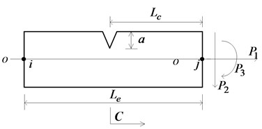
The crack type used in this paper is an opening mode crack, which means that the crack remains open during vibration. A part-through crack is a typical form of the general damage existing in pipe-like structures, as shown in Fig. 1, where is the crack depth within the top solid-sectional region; and are the internal and external diameters respectively. It is assumed that the element of a cracked pipe is under the combined action of axial force , shearing force , and bending moment . For the part-through crack shown in Fig. 1(b), the stress intensity factor cannot be obtained directly for calculating the local flexibility. Inspired by Dimarogonas’s study [10] of the analytical estimation of the local flexibility of a cracked shaft, the crack region is discretized into a series of rectangular strips and the additional strain energy of each strip is calculated based on the plane cracked beam theory. Thereby, local flexibility equations of the cracked pipe are established and the corresponding flexibility coefficients are calculated by the numerical integration.
With reference to the geometrical relations illustrated in Fig. 1(b), the following equations are obtained:
where , are the ordinate and abscissa that measure the crack depth and the deviation of the crack edge, respectively; is half the width of the horizontal section at the depth of ; is the local depth of the integration strip; is the total height of the integration strip.
Fig. 1a) Cracked pipe element, b) cracked section geometry
a)
b)
It is assumed that the crack region stress is still in a linear elastic state under load. Based on linear fracture mechanics theory, the additional strain energy [2] due to the crack can be expressed as:
where is the strain energy release rate function and is the effective crack area. The strain energy release rate function can be formulated as:
where , , and are the stress intensity factors with Mode I under loads , , and respectively. is the stress intensity factor with Mode II under shearing force. For plane stress problems, , and for plane strain problems, equals , where is the elastic modulus and is the Poisson ratio.
For a cracked pipe subjected to axial force , shearing force , and bending moment , the stress intensity factors of each strip of the cracked pipe can be expressed as:
where ( 1, 2, 3) denotes the axial force, shearing force, and bending moment, respectively. Sectional parameter . , , and are the correction parameters for stress intensity factors, and every term has the following expression (Tada, et al. [24]):
where: , ,
Based on Castigliano’s theorem, the additional displacement due to a crack can be expressed as:
The local flexibility equations of the cracked element are obtained:
where (, 1, 2, 3) is the local flexibility coefficient for a cracked pipe subjected to different loads.
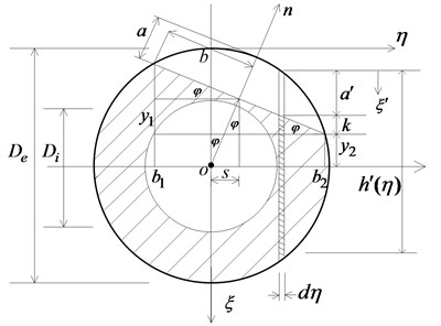
In the cracked pipe shown in Fig. 2, subjected to bending moment in the vertical plane, a part of the crack section is in a tension zone while the other part is in a compression zone. If the crack tip is located in a tension zone, the crack edge will be opened, leading to a lower bending stiffness. If the crack tip is located in a compression zone, the crack edge is closed and the bending stiffness can be approximately equal to that in the undamaged condition. It is illustrated that the local flexibility coefficient of the cracked pipe is closely related to the direction of the crack orientation with respect to the bending moment. With the changes in the crack orientation , the following three states can be present in the overall crack surface during the dynamic response: 1) a fully opened state; 2) a partly opened-partly closed state; 3) a fully closed state.
Fig. 2Sketch of tensile and pressure area subjected to bending moment
It has been demonstrated that the local flexibility of a cracked structure subjected to bending moment is only affected by an open crack and is almost unaffected by a closed crack. However, the local flexibility of a cracked structure subjected to shearing force or axial force is almost unaffected by the state of the crack, whether open or closed. Therefore, it is necessary to take into account the contribution from the total strain energy of the overall crack surface.
By setting integral variables , , we obtain:
Substituting Eqs. (3-7) into Eq. (12), the dimensionless local flexibility coefficient of the cracked pipe element with a straight front and part-through crack can be obtained:
where:
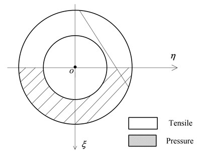
Chasalevris and Papadopoulos [14] demonstrated that for a crack shaft with any orientation, due to the limitations of the stress intensity factor, high accuracy of the local flexibility can be obtained under bending moment when the angle is between –30° and 30°. Along with any change in crack orientation , however, the effective integration area of the crack surface is correspondingly changed. When ( is the critical angle), the crack’s partial cross-section begins to enter the compression zone and the effective integration area gradually decreases. When ( is the closed angle), the crack is completely located in the compression zone and the value of is zero.
Fig. 3a) bending in horizontal plane; b) bending in vertical plane
Based on the geometric relations in Fig. 1(b), , can be expressed as:
Further, the following equations can be obtained:
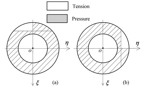
where , and are the functions of the relative crack depth. For cracked pipes with same depth, the local flexibility coefficients are equivalent when the bending moment is within the vertical plane ( 90°) or the horizontal plane ( 0°). When satisfies 60° 90°, the proposed local flexibility coefficients can also be expressed as:
Therefore, when the crack orientation is between 0° and 180°, calculation of the local flexibility coefficient can be divided into three segments, 0° 30°, 60° 90°, and 180°. Based on the derivability and continuity of each segment, the local flexibility coefficients can be calculated based on B-spline curve interpolation with respect to 30° 60° and 90° . In summary, dimensionless local flexibility coefficients of a part-through cracked pipe can be calculated for any crack orientation.
3. Calculation and validation of proposed local flexibility coefficients
3.1. Calculation of the flexibility coefficients
Integrated formulas on the right side of Eqs. (14)-(19) are double integrations with respect to , and the inner limits are expressed as a function of . These integration formulas are often complex in terms of analytical approaches. In principle, numerical integration is generally used to solve the previous equations. Among many numerical integrations, an adaptive quadrature-revisited (AQR) integration is adopted to compute the () (, 1, 2, 3). Some advantages of the AQR method are favorable efficiency, high accuracy, and robustness, and therefore it has been widely used for complex integrations. For details of the fundamental theory of the AQR method, please refer to Gander and Gautschi [25]. Integrated programs for the solution of local flexibility () are developed by MATLAB software [26, 27]. For given physical parameters and geometry parameters, dimensionless local flexibility coefficients of a cracked pipe can be calculated with any crack depth and any crack orientation, based on LFIP.
This paper focuses on the dimensionless local flexibility coefficient of a cracked pipe with any angle . With 0.5, 12 different crack orientations are selected, as listed in Table 1. The values of and are calculated for different crack depths, as listed in Table 2.
Table 1Values of the angle φ
0° | 10° | 20° | 30° | |
60° | 70° | 80° | 90° | |
150° | 160° | 170° | 180° |
Table 2Values of φcr and φcl with different crack depths
0.04 | 66.926° | 113.074° |
0.08 | 57.140° | 122.860° |
0.12 | 49.464° | 130.536° |
0.16 | 42.843° | 137.157° |
0.20 | 36.869° | 141.131° |
0.24 | 31.332° | 148.668° |
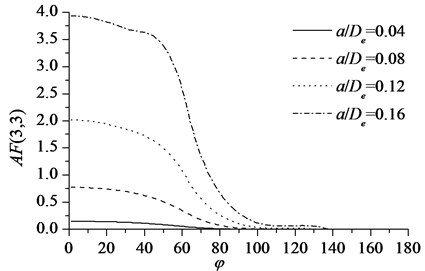
According to the results of Table 2, when , the crack edge is fully closed and the dimensional local flexibility coefficient . When , the crack edge is fully open and the dimensional local flexibility coefficient appears at its maximum. When , one segment of the crack edge is open and the other segment is closed and the values of are calculated as shown in Fig. 4. It is illustrated that: 1) with same crack orientation , the value of increases with the crack propagation; 2) with invariable crack depth, the value of decreases with an increase in the crack orientation .
Fig. 4Values of AF(3, 3) versus different crack orientation φ
3.2. Validation of the proposed calculation solution
Model testing is an effective way of verifying theoretical calculation. In this paper, Naniwadekar’s model test and the authors' model test are used to validated the proposed general solution of local flexibility coefficients of cracked pipe.
3.2.1. The validation by Naniwadekar’s test
Naniwadekar et al. [23] studied crack prediction in pipe with different orientations based on natural frequency. In their research, the rotational spring of a crack in different orientations was obtained by a model test. In their model test, the crack was made by a wire cut, with the cutting width of nearly 0.2 mm. When the crack orientation , the compression zone was not closed, and it was indicated that the human-made crack was somewhat different from an actual crack. Therefore, the test data for crack orientations 0°, 10°, 20°, and 30° are compared here. Physical parameters and crack parameters are listed in Table 3.
Table 3Physical parameters and crack parameters
Parameters | / m 0.0278 | / m 0.0378 | / (kg / m3) 7860 | / 173.8 |
Crack depth () | 0.2 | 0.4 | 0.6 | 0.8 |
Crack orientation () | 0° | 10° | 20° | 30° |
The results of proposed method vs Naniwadekar’s test are shown in Fig. 5.
Fig. 5Calculating results and Naniwadekar’s test
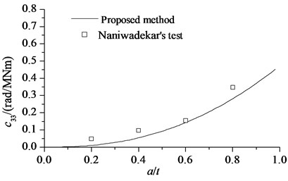
a)0°
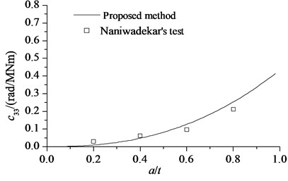
b)30°
From Eq. (19), the local flexibility of under bending moment was obtained as:
3.2.2. The validation by model test
In order to further validate the proposed theoretical calculation. the model test by vibration method is conducted in this paper. Cantilever support as a constraint condition used in this test in order to simulate the real situation of fixed end constraint, it is need that the cantilever supporting stiffness is large enough for relative stiffness of the specimen in the test device. Therefore, four M16 bolts are used for fixed cantilever support in the shaking table. In order to ensure each specimen restraint stiffness is as equal as possible during test process, the constant torque ( 120 N·m) wrench is used for replacing the pipe specimen. The test device and picture schematically is shown in Fig. 6 and Fig. 7.
Fig. 6Sketch of experimental setup
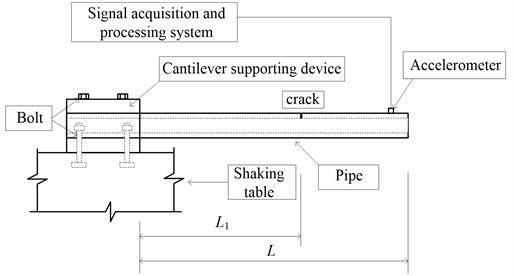
Fig. 7Photograph of experimental setup
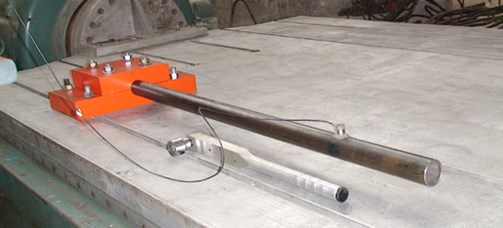
Seamless steel tube is used as pipe specimen. Pipe elastic model is 200 GPa, and the Poisson’s ratio is 0.27. the outer diameter of the pipe is 42 mm, the inner diameter is 30mm. Pipe crack is made by using wire cutting, and the corresponding crack depth are made 1, 2, 3, 4 and 5 mm, respectively, for different pipe specimen. In this test, the length of the cantilever pipe is 707 mm, and the crack position is 10 mm. Vibration test is adopted by impulse excitation. Bruel & Kjaer piezoelectric accelerometer is used in the test, and the sampling frequency is 2560 Hz.
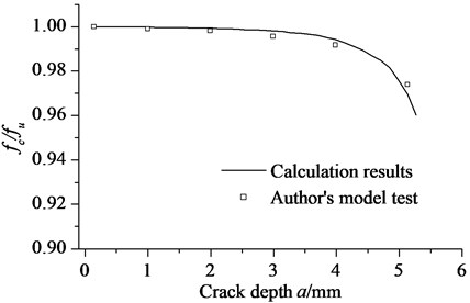
For a cracked pipe structure, based on the calculated local flexibility coefficients, a finite element model (FEM) for vibration analysis was established by Yu et al. [26], and natural frequency can be calculated by FEM. In this paper, the natural frequency of cantilever cracked pipe will be obtained by model test and FEM based on local flexibility, respectively. The results of calculation results and authors’ model test are shown in Fig. 8. where, crack orientation is 10°, is natural frequency for cantilever cracked pipe, and is natural frequency for undamaged cantilever pipe.
As illustrated in Fig. 5 and Fig. 8, the calculation results by the proposed method are identical to the results of model testing by Naniwadekar’s and the authors within acceptable error. The errors derive from two sources:
1) The crack forms used in the calculation are different from those in the model testing. In the model testing, the crack was made using wire cutting. Although the crack cut was small, it was still different from an actual crack. The crack style used in this paper is a breathing crack, and crack opening and closing were dependent on the external force and the crack orientation.
2) Error inevitably appears in the numerical calculation. Practical pipe is not completely under plane strain or plane stress, and the value of can have a greater or lesser influence on calculation results. Furthermore, the use of discrete rectangular bands results in integral approximation. Of course, there were inevitably some measurement and manufacturing errors in the model testing by Naniwadekar’s and authors’.
Fig. 8Calculating results and authors’ model test
It has been demonstrated here that our proposed method for local flexibility calculation is correct and reasonable, avoids the necessity of considerable experimental work for engineering applications, thereby saving time costs and financial resources. In summary, the proposed method is competent for local flexibility coefficient calculation with respect to any crack orientation and any crack depth in pipe. It can be used for vibration analysis and crack identification in cracked pipe, and improves the deficiencies of the existing crack model of pipe.
4. Numerical example for free vibration of cracked pipe by proposed method
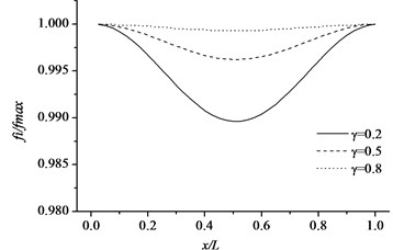
Free vibration characteristics of the pipe-like structure, such as a cantilever pipe and a simple supported pipe with respect to different sectional parameter and crack location, are studied assuming that the cracked pipes have same crack depth ratio and crack orientation. The uniform cracked pipe structures, with different sectional parameters are used in the numerical calculation. The geometrical properties of the beam are length 1 m, external diameter 0.04, sectional parameters 0.2, 0.5 and 0.8. The physical parameters 200 GPa, 7850 kg/m3 and 0.27. Fig. 9 and Fig. 10 illustrate the non-dimensional natural frequencies of the cracked pipe as a function of the sectional parameter () and different crack depth ratios with respect to the first three modes. In this study, non-dimensional natural frequencies are normalized by where and refer to the natural frequency of the cracked and non-cracked pipe-like structure, respectively. It can be obviously seen from Fig. 9 and Fig. 10 that natural frequencies of the cracked pipe are lower than those of corresponding intact pipe, and when the sectional parameter decreases, the frequency reduction gets higher. When the parameter decreases, the pipe thickness will increase because more strain energy will release due to the bigger crack interface based on the strain energy release principle.
It is illustrated from Fig. 9 and Fig. 10 that the changes in normalized natural frequencies depend on how close the crack is to that mode shape node. The reduction in the natural frequency of a mode is larger if the crack is closer to the anti-nodal point of that mode shape. The essential reason of this change is that when the crack is located on one of the mode shape anti-nodes, its influence on the dynamic characteristics of the structure is little. The influence becomes significant when the crack is near or at a point of the maximum amplitude of the mode shapes.
Fig. 9Variations of the natural frequencies of the cracked pipe in terms of normalized crack depth and different sectional size for the first three modes (cantilever pipe)
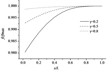
a) Mode 1
b) Mode 2
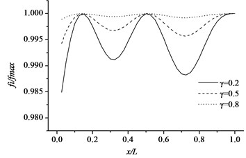
c) Mode 3
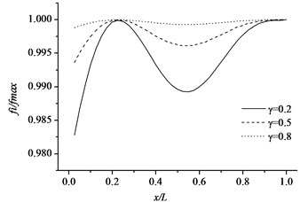
Fig. 10Variations of the natural frequencies of the cracked pipe in terms of normalized crack depth and different sectional size for the first three modes (simple supported pipe)
a) Mode 1
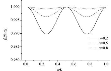
b) Mode 2
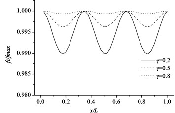
c) Mode 3
5. Conclusions
In this paper, local flexibility coefficients of the pipe with a part-through crack under axial force, shearing force and bending moment are derived by the application of linear fracture mechanics theory and the strain energy release rate principle. The deduced local flexibility coefficients are considered in terms of variations of open and closed states of the crack surface with any crack orientation, and are calculated by an adaptive Simpson numerical integration procedure developed by MATLAB. The principle for calculating local flexibility coefficients with crack orientation is divided into five segments. For crack orientations 0°-180°, the local flexibility coefficients with 0° 30°, 60° 90°, and 180° are obtained directly, and the local flexibility coefficients with 30° 60° and 90° are obtained by B-spline curve interpolation based on the above analysis.
The results of model testing by Naniwadekar’s and authors are used in this paper as comparable data for verifying the calculation results of proposed local flexibility coefficients. The results indicate that the proposed calculation values are consistent with the experimental values, demonstrating that the proposed local flexibility coefficients are exact. The proposed method provides the basis for vibration analysis of a cracked pipe. Free vibration characteristics of the pipe-like structure, such as a cantilever pipe and a simple supported pipe with respect to different sectional parameter and crack location can be analyzed based on proposed method.
References
-
Dimarogonas A. D. Vibration of cracked structure: a state of the art review. Engineering Fracture Mechanics, Vol. 55, Issue 5, 1996, p. 831-857.
-
Papadopoulos C. A. The strain energy release approach for modeling cracks in rotors: a state of the art review. Mechanical Systems and Signal Processing, Vol. 22, Issue 4, 2008, p. 763-789.
-
Petroski H. J. simple static and dynamic models for the cracked elastic beam. International Journal of Fracture, Vol. 17, Issue 1, 1981, p. 71-76.
-
Petroski H. J. Stability of a crack in a cantilever beam undergoing large plastic deformation after impact. International Journal of Pressure Vessels and Piping, Vol. 16, Issue 4, 1984, p. 285-298.
-
Silva J. M. M., Gomez A. J. M. A. Experimental dynamic analysis of cracked free-free beams. Experimental Mechanics, Vol. 30, Issue 1, 1990, p. 20-25.
-
Christides S., Barr A. D. S. One dimensional theory of cracked Bernoulli-Euler beams. International Journal of Mechanical Science, Vol. 26, Issues 11-12, 1984, p. 639-648.
-
Chondros T. G., Dimarogonas A. D., Yao J. A continuous cracked beam vibration theory. Journal of Sound and Vibration, Vol. 215, Issue 1, 1998, p. 17-34.
-
Chondros T. G., Dimarogonas A. D., Yao J. Vibration of a beam with a breathing crack. Journal of Sound and Vibration, Vol. 239, Issue 1, 2001, p. 57-67.
-
Irwin G. R. Analysis of stresses and strains near the end of a crack traversing a plate. Journal of Applied Mechanics. Vol. 24, 1957, p. 361-364.
-
Dimarogonas A. D. Analytical Methods in Rotor Dynamics. Applied Science Publishers, Essex, 1983.
-
Papadopoulos C. A., Dimarogonas A. D. Coupling longitudinal and bending vibrations of a cracked shaft with an open crack. Journal of Sound and Vibration, Vol. 117, Issue 1, 1987, p. 81-93.
-
Nikolakopoulos P. G., Katsareas D. E., Papadopoulos C. A. Crack identification in frame structures. Computers and Structures, Vol. 64, Issues 1-4, 1997, p. 389-406.
-
Papadopoulos C. A. Some comments on the calculation of the local flexibility of cracked shafts. Journal of Sound and Vibration, Vol. 278, Issues 4-5, 2004, p. 1205-1211.
-
Chasalevris A. C., Papadopoulos C. A. Identification of multiple cracks in beams under bending. Mechanical Systems and Signal Processing, Vol. 20, Issue 7, 2006, p. 1631-1673.
-
Chasalevris A. C., Papadopoulos C. A. Coupled horizontal and vertical bending vibrations of a stationary shaft with two cracks. Journal of Sound and Vibration, Vol. 309, Issues 3-5, 2008, p. 507-528.
-
Liu J., Zhu W. D., Charalambides P. G., et al. A dynamic model of a cantilever beam with a closed, embedded horizontal crack including local flexibilities at crack tips. Journal of Sound and Vibration, Vol. 382, 2016, p. 274-290.
-
Qian G. L., Gu S. N., Jiang J. S. The dynamic behavior and crack detection of a beam with a crack. Journal of Sound and Vibration, Vol. 138, Issue 2, 1990, p. 233-243.
-
Gounaris G., Dimarogonas A. D. A finite element of a cracked prismatic beam for structural analysis. Computers and Structures, Vol. 28, Issue 3, 1988, p. 309-313.
-
Nahvi H., Jabbari M. Crack detection in beams using experimental modal data and finite element model. International Journal of Mechanical Sciences, Vol. 47, 2005, p. 1477-1497.
-
Ruotolo R., Surace C., Crespo P., et al. Harmonic analysis of the vibrations of a cantilevered beam with a closing crack. Computers and Structures, Vol. 61, Issue 6, 1996, p. 1057-1074.
-
Liu D., Gurgenci H., Veidt M. Crack detection in hollow section structures through the coupled response measurements. Journal of Sound and Vibration, Vol. 261, Issue 1, 2003, p. 17-29.
-
Zheng D. Y., Fan S. Vibration and stability of cracked hollow-sectional beams. Journal of Sound and Vibration, Vol. 267, Issue 4, 2003, p. 933-954.
-
Naniwadekar M. R., Naik S., Maiti S. K. On prediction of crack in different orientations in pipe using frequency based approach. Mechanical Systems and Signal Processing, Vol. 22, Issue 3, 2008, p. 693-708.
-
Tada H., Paris P. C., Irwin G. R. The Stress Analysis of Cracks Handbooks (Third Edition). ASME Press, New York, 2000.
-
Gander W., Gautschi W. Adaptive Quadrature-Revisited. BIT 40, 2000, p. 84-101.
-
Yu Z. H., Zhang L. B., Hu J. Q., Hu J. S. Damage modeling and simulation of vibrating pipe with part-through circumferential crack. Journal of Vibroengineering, Vol. 18, Issue 4, 2016, p. 2176-2185.
-
Hu J. S., Sun W. Y. Free vibration analysis of pipe with a part-through crack. The 3rd World Conference on Safety of Oil and Gas Industry, 2010, p. 302-308.
Cited by
About this article

This research is supported by Education reform project of China Institute of Industrial Relations (JG1644).
