Abstract
This paper discusses the formulation and solution for the problem of damped transverse vibrations of the type frame with open cracks. Dissipation of vibration energy in the frame results from the movement constraint in the column and bolt support (constructional damping) and internal damping of viscoelastic material of the frame (rheological model by Kelvin-Voigt). Presence of a crack impacts local flexibility that has an effect on frame vibration response. The boundary problem for the above system was formulated based on the Hamilton’s principle and solved numerically for the complex eigenvalues . The effect of the crack depth and its location on damped vibration was presented. The effect of both types of damping on the degree of amplitude decay was also presented.
1. Introduction
Cracks are one of the most common causes of structural defects. This kind of damage to structural components may significantly affect machine performance. The dynamic behaviour of a system with a crack on a structural component is changed. Crack in a structure has also a major effect on object vibration. Taking into consideration the constructional and internal damping (and its effect on vibration of the structure) leads to important and interested conclusions. This study was concerned with an effect of the location and depth of cracks on damped vibration of the type frame for selected damping coefficients.
The theoretical, numerical and experimental analysis of vibrations and stability of two types of flat frames i.e. -shaped and shaped were presented in studies [1, 2], respectively. The frames were loaded with longitudinal force in relation to the bolt or loaded by a force oriented toward the positive pole. No cracks in the structure were found for any of the frames.
Presence of a crack in an elastic structural component leads to considerable local flexibility due to the strain energy concentration near the crack tip under load. The effect of a transverse open crack on free vibration of a simply supported Bernoulli-Euler prismatic beam was presented in the study [3]. In order to model the cracks and their continuous flexibility, authors used the displacement field near the crack, found based on fracture mechanics methods. They presented results of two independent cases of evaluation of the problem of crack identification in structures: the continuous cracked beam vibration theory and the lumped cracked beam vibration analysis. The study [4] presented the method to identify cracks based on the assumption of a transverse surface crack. The proposed method is non-invasive and can be easily implemented and used to monitor crack growth. A local flexibility matrix describes a force – displacement relationship. The transverse open single-sided crack is modelled by a rotational spring with calculated stiffness constant. The authors of the study [5] presented an analysis of the effect of two open cracks on frequencies of natural flexural vibrations in a cantilever beam. In this case, the two types of cracks are to be considered: open double-sided and open single-sided. Stability and natural vibration of columns composed of one or several elements with crack in the internal rod were presented in [6-8]. The study [6] described the effect of cracks in a structure on instability and free vibrations of stepped columns. In papers [7, 8], the vibration frequency, bifurcation load magnitude, bifurcation load-crack size relationship, and amplitude-vibration frequency relationship were studied. The crack was modelled using a rotational spring with a linear characteristic. The results of the numerical calculations presented in [6-8] indicated that the crack size has a significant effect on bifurcation load magnitude and vibration frequency.
The effect of a local flexibility (crack) on the vibrations of different type of frames was presented in publications [9-11]. The study [9] discussed the impact of crack localization on transverse vibrations of type frame with and without additional discrete elements. Transverse and longitudinal vibrations of two and three-bar frames with cracks were presented in the study [10]. In [9] and [10], local flexibility (crack) was modelled by a local stiffness matrix. A modal analysis of two-member open frame with a transverse crack was the focus of the study [11]. The authors analysed free vibrations of a 3D model of open -shape frame for various crack dimensions, locations and values of tip mass for both horizontal and vertical members. The findings of the research presented in [3-11] showed that natural frequency of the system is lower for location of the crack near fixed end region and increases for farther regions.
In these studies authors focused on the description of stability, free vibration or the effect of cracks on frame vibration, whereas the effect of damping was not taken into consideration. In the study [12], authors formulated and solved the problem of transverse damped vibrations of T type frame with rotational dampers in the points of frame mounting and in the supports.
The focus of the present study is on the analysis of damped vibrations of the type frame with cracks. Previous studies in this field have examined integrated transverse and longitudinal damped vibrations of the type frame without cracks in a structure [13]. In the Bernoulli-Euler beam model adopted in the study, dissipation of vibration energy derives from the damping. Fig. 1 presents two types of damping: constructional damping in the column support and in fixing bolt frame support and internal damping of the viscoelastic material of the frame. The rotational viscous dampers were used to model the constructional damping of supports. Internal damping in individual frame beams was denoted by . The complex eigenvalue of the frame was given. The real part of the solution described the damped vibration frequency. The imaginary part of the solution described the degree of amplitude decay. The numerical analysis was focused on an effect of the location and depth of cracks on damped vibration frequency and on degree of amplitude decay of the type frame. The results obtained were presented by means of three-, and two-dimensional graphs. Solutions for additional control of system dynamics and support for early detection of damages are being explored. The problem presented in this work necessitates undertaking actions oriented at the identification. Such actions are: mathematical modelling (included in this paper), experimental research, parameter estimation, model verification and optimization. The all or some of identification stages (actions) are the subject of research for many authors, ex. [15-17], which served as an inspiration to undertake this study.
2. Physical and mathematical models of the system
The diagram of the system discussed in the present study is shown in Fig. 1. In this system, cracks are modelled by rotational spring . Rotational cracks compliance was assumed to be dominant in the local flexibility matrix as in [4] in the following form:
where:
and:
where: – compliance, – Young’s modulus, – moments of inertia for cross-sectional areas of beams, – dimensionless local compliance function [4], – crack depth, – height of the column and bolt frame, 1, 2.
The physical and mathematical model of the system takes into account the viscoelasticity of the material characterized by Young’s modulus , viscosity coefficients (internal damping) and movement resistance in the supports modelled by rotational viscous dampers (constructional damping).
Fig. 1The diagram of the Γ type frame with viscous end conditions and cracks in the structure
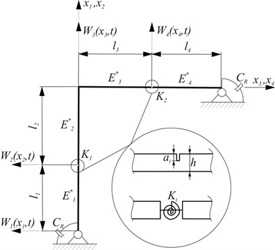
Equations of motion for individual beams were denoted as:
where: – transverse displacements, – Young’s modulus, – viscosity coefficients, – cross-sectional areas of beams, – moments of inertia for cross-sectional areas, – beam material densities, – time, – spatial coordinate, 1, 2, 3, 4.
Solutions of Eq. (4) are in the form:
where – complex eigenvalue of the system, , .
Substitution of Eq. (5) into Eq. (4) leads to:
where:
Geometrical boundary conditions and continuity conditions are given by:
Natural boundary conditions of the system can be presented in the following form:
The solution for the Eq. (5) is given by:
where:
Substitution of Eq. (9) to Eq. (8a-b) yields a homogeneous system of equations with respect to unknown constants , which, in the matrix form, can be written as:
where:
The system has a non-trivial solution if the determinant of the matrix coefficient (with constant ) equals to zero:
Solution of the above equation (Eq. (13)) yields the real and imaginary parts of the vibration frequency.
3. Results of numerical calculations
Calculations were performed for the variable crack locations in the column (first crack) and in the bolt frame (second crack), selected depths of cracks and selected values of damping coefficients. The data are contained in Table 1.
3.1. Parameters of the system
The non-dimensional parameters were used for: internal damping of viscoelastic material of beams – , constructional damping in the supports – , location of crack in the column and in the bolt – and , respectively:
where:
Table 1Parameters of the model
Parameter | Value |
Total length of the column [m] | 2 |
Total length of the bolt [m] | 2 |
Length of the beam [m] | Variable |
Length of the beam [m] | Variable |
Length of the beam [m] | Variable |
Length of the beam [m] | Variable |
Height of the column and bolt [m] | 0.1 |
Width of the column and bolt [m] | 0.1 |
Crack depth in the column | Variable |
Crack depth in the column | Variable |
Location of crack in the column | Variable |
Location of crack in the column | Variable |
Young modulus of the column and bolt [Pa] | 2.1e11 |
Internal damping coefficient | 0.001 |
Material density in column and bolt [kg/m3] | 7860 |
Value of used in computations is internal damping coefficient of homogeneous structural steel without coating [14]. Selected values of from 0 to 2 describe the main effect of constructional damping coefficient on damped vibration frequency and on the degree of vibration amplitude decay. No effect on and for 0 was found whereas the highest effect on and was observed for 0.4 and 2, respectively.
3.2. Presentation of research results
The results of the calculations are presented in Figs. 2-10. The relationships between the first (a) and the second (b) natural frequency of the frame and the depth and location of crack in the column without damping are presented in Fig. 2. The relationships represent reference results. The comparison of the results with those reported in literature demonstrated that the increase in the value of crack depth leads to the decrease in eigenvalues of the undamped system.
Fig. 2Relationship between the first and the second natural frequencies of the frame and location of: a) the first crack without the second crack, b) without damping
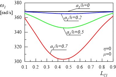
a)
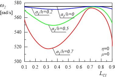
b)
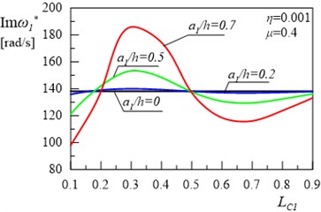
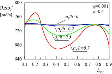
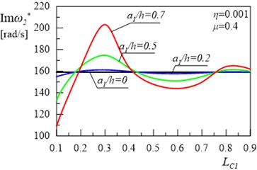
The aim of this paper is to analyse the effect of damping on vibration of a type frame with cracks. In the first case, there was a single crack on the column, whereas in the second case, there were two cracks: one on the column and one on the bolt frame. The relationships of the real and the imaginary terms of the first and the second eigenvalue of the frame for different locations of first crack and depth are presented in Figs. 3(a), 3(b), 4(a) and 4(b). Calculations were performed for damping coefficients 0.001 and 0.4. Figs. 3-4 show some areas of the curves, with the increase in the value of the crack depth leading to the increase in eigenvalues of the damped system.
Fig. 3Relationship between the first damped eigenvalue of the frame and location of the first crack without the second crack
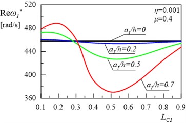
a)
b)
Fig. 4Relationship between the second damped eigenvalue of the frame and location of the first crack without the second crack
a)
b)
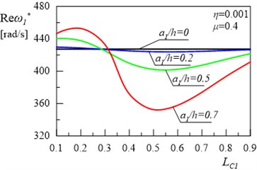
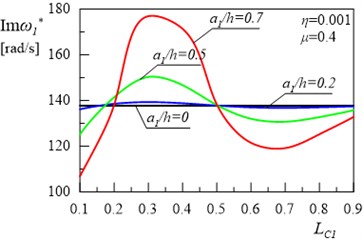
Fig. 5The relationship between the first damped eigenvalue of the frame and location of the first crack for the depth of the second crack a2/h= 0.5 and its location LC2= 0.5
a)
b)
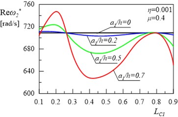
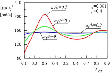
Fig. 5(a) and 5(b) present the relationships between the real and imaginary parts of the first eigenvalue for the frame and the variable value of depth and location of the crack in the column for internal damping coefficient 0.001, constructional damping coefficient 0.4 and for the depth 0.5 and location 0.5 of the crack in the frame bolt. Figs. 6(a) and 6(b) present the same relationships for the second eigenvalue for the frame. The comparison of the results shown in Figs. 3, 4 with the results presented in Figs. 5, 6 reveals that, in this second case, changes in the location of the crack on the column lead to the increase in both real and imaginary parts of the first and the second eigenvalue of the system. Some areas of the curves are also non-monotonic as in Figs. 3-4.
Fig. 6The relationship between the second damped eigenvalue of the frame and location of the first crack for the depth of the second crack a2/h= 0.5 and its location LC2= 0.5
a)
b)
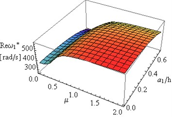
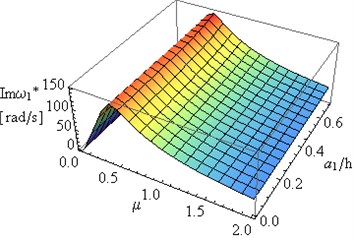
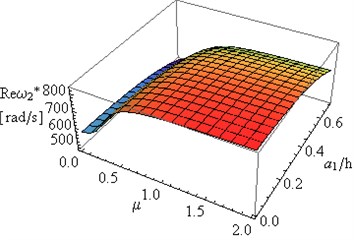
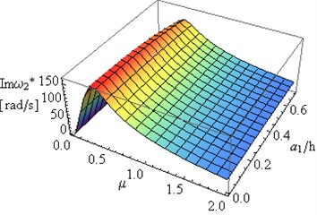
Further part of the study was focused on the determination of the relationship of the first and the second eigenvalue of frame on changes in constructional damping coefficient and the depth of both cracks at 0.5 and internal damping coefficient 0.001. Results of investigations are presented in Figs. 7(a), 7(b), 8(a) and 8(b). A simultaneous change in the depth of both cracks causes insignificant changes in , , and of the system. Considerable changes can be observed in of the first and the second eigenvalue with changes in the value of constructional damping .
Fig. 7The dependence of: a) real Reω*, b) imaginary Imω* parts of the first eigenvalue for the frame on the constructional damping μ and crack depth a1/h for a2/h=a1/h and LC1=LC2= 0.5
a)
b)
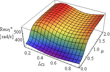
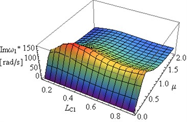
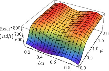
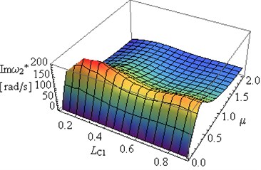
Figs. 9(a) and 9(b) present the dependence of the real and the imaginary part of the first eigenvalue of the frame on changes in constructional damping coefficient and changes in cracks location of both cracks at 0.5 and for internal damping coefficient 0.001. The effect of simultaneous changes in crack location and in constructional damping coefficient on the second eigenvalue of the frame was presented in Figs. 10(a) and 10(b). Substantial changes can be observed in the first and the second eigenvalue of the system for different crack locations. The constructional damping causes similar changes in presented in Figs. 7(b), 8(b) to those in in Figs. 9(b), 10(b).
Fig. 8The dependence of: a) real Reω*, b) imaginary Imω* parts of the second eigenvalue for the frame on the constructional damping μ and crack depth a1/h for a2/h=a1/h and LC1=LC2= 0.5
a)
b)
Fig. 9The dependence of: a) real Reω*, b) imaginary Imω* part of the first eigenvalue for the frame on the constructional damping μ and crack location LC1 for a2/h=a1/h= 0.5 and LC1=LC2
a)
b)
Fig. 10The dependence of: a) real Reω*, b) imaginary Imω* part of the second eigenvalue for the frame on the constructional damping μ and crack location LC1 for a2/h=a1/h= 0.5 and LC1=LC2
a)
b)
Important changes can be observed in and in the case of changes in the constructional damping coefficients (Figs. 7(b), 8(b), 9(b), 10(b)).
Limitation of the scope of the study to the analysis of the two first eigenvalues of the system results from their fundamental importance to engineering practice.
4. Conclusions
This paper analysed two cases of crack location. The effect of damping on vibration of type frame was examined. The findings of the study lead to the following conclusions:
– Taking into account the effect of constructional damping on vibration of the frame causes quantitative and qualitative functional changes, as shown in Figs. 2-4. These significant changes, between the real part of the first two eigenvalues (Figs. 3(a), 4(a)) and the first two natural frequencies (Fig. 2) resulted from movement constraint of the supports of the frame.
– Location of the crack in the system with the rotational damper in the support has a significant effect on in both the first and the second eigenvalue of the system. If the crack is located near the support, up to 0.3, the increase in the value of and its character (Figs. 3(a), 4(a)) is observed compared to the system where dumping was not taken into consideration (Fig. 2.). In the range of discussed in the study, the crack depth also has a significant effect on the values of and .
– The method adopted in the study can be successfully used in non-invasive monitoring of the object status. The numerical analysis should assume the presence of natural damping (internal damping and tribological wear or other movement resistance such as structural damping) which occurs in the system studied in order to obtain reference results for the systems with and without cracks. The results of the actual examination of the object, obtained by means of modal analysis should be compared with reference results.
– The adopted methodology needs to be verified experimentally, which will be the aim of future research.
– An increase in results in the increase in to maximum values, followed by 0 where (Figs. 7-10).
– An increase in (Figs. 7-10) is caused by the intervention in the conditions of the frame supports, and in extreme cases where , the supports are changed from joint into rigid mountings.
– Analysis of the results presented in Figs. 7-10 allows for determination of certain geometrical parameters, such as depth and location of crack and constructional damping parameters of the frame, at which the degree of amplitude decay is the highest i.e. the vibration amplitude decreases the fastest.
– The rotational damper mounted in the support can be considered an additional method to control system dynamics.
References
-
Szmidla J. Vibrations and stability of T-type frame loaded by longitudinal force in relation to its bolt. Thin-Walled Structures, Vol. 45, 2007, p. 931-935.
-
Szmidla J. Free vibrations of a Γ type planar frame loaded by a follower force directed towards the positive pole. Vibrations in Physical Systems, Vol. 24, 2010, p. 405-410.
-
Chondros T. G., Dimarogonas A. D., Yao J. Continuous cracked beam vibration theory. Journal of Sound and Vibration, Vol. 215, Issue 1, 1998, p. 17-34.
-
Rizos P. F., Aspragathos N., Dimarogonas A. D. Identification of crack location and magnitude in a cantilever beam from the vibration modes. Journal of Sound and Vibration, Vol. 138, Issue 3, 1990, p. 381-388.
-
Ostachowicz W. M., Krawczuk M. Analysis of the effect of cracks on the natural frequencies of a cantilever beam. Journal of Sound and Vibration, Vol. 150, Issue 2, 1991, p. 191-201.
-
Kukla S. Free vibrations and stability of stepped columns with cracks. Journal of Sound and Vibration, Vol. 319, 2009, p. 1301-1311.
-
Sokół K., Uzny S. Instability and vibration of multi-member columns subjected to Euler’s load. Archive of Applied Mechanics, Vol. 86, 2016, p. 883-905.
-
Sokół K. Linear and non-linear vibrations of a column with an internal crack. Journal of Engineering Mechanics, Vol. 140, Issue 5, 2014, https://doi.org/10.1061/(ASCE)EM.1943-7889.0000719.
-
Ratazzi A. R., Bambill D. V. B., Rossit C. A. Vibrations of a frame structure with a crack. Mecánica Computacional, Vol. 32, 2013, p. 3563-3574.
-
Grossi R. O., Albarracín C. M. Variational approach to vibrations of frames with inclined members, Applied Acoustics, Vol. 74, 2013, p. 325-334.
-
Mamatha Y. P., Sujith Kumar S., Vivek G., Sumanth D. R., Vinay N. Analysis of crack influence on an open frame L-structure using FEM. International Journal of Engineering Research and General Science, Vol. 4, Issue 4, 2016, p. 108-117.
-
Sochacki W., Rosikon P., Topczewska S. Constructional damping mounting influence on T type frame vibrations. Journal of Vibroengineering, Vol. 15, Issue 4, 2013, p. 1866-1872.
-
Sochacki W., Bold M. Transverse and longitudinal damped vibration of the GAMMA type frame. Journal of Applied Mathematics and Computational Mechanics, Vol. 15, Issue 2, 2016, p. 147-155.
-
Liang J. W., Feeny B. F. Identifying Coulomb and viscous friction from free vibration decrements. Nonlinear Dynamics, Vol. 16, 1998, p. 337-347.
-
Yu Xue, Jiongming Jiang, Binping Zhao, Tinghuai Ma A self-adaptive articial bee colony algorithm based on global best for global optimization. Soft Computing, 2017, https://doi.org/10.1007/s00500-017-2547-1.
-
Qi Liu, Weidong Cai, Jian Shen, Zhangjie Fu, Xiaodong Liu, Nigel Linge A speculative approach to spatial‐temporal efficiency with multi‐objective optimization in a heterogeneous cloud environment. Security and Communication Networks, Vol. 9, Issue 17, 2016, p. 4002-4012.
-
Qing Tian, Songcan Chen Cross-heterogeneous-database age estimation through correlation representation learning. Neurocomputing, Vol. 238, 2017, p. 286-295.
