Abstract
This paper presents a formulation and solution for the problem of transverse and longitudinal vibration of the portal frame with damping. The dissipation of vibration energy in the model is caused by simultaneous constructional, internal and external damping. The eigenvalues of the system for a selected and variable parameters were calculated. The effect of different type of damping on amplitude decay factor was presented.
1. Introduction
The dynamic properties of frames with additional discrete elements and crack, or loaded by the force were investigated in works [1-8]. In these works, authors formulated and solved the problem of stability and / or free and forced vibration of different type of frame without damping in considered system. In papers [1] and [2] the analysis of vibrations and stability of loaded and type frames were presented. In [3] was presented the results of research the influence of elastically restrained of supports on eigenfrequencies of frame. The influence of a crack depth and location on the vibrations of frame were presented in works [4-6]. The eigenfrequencies of a type frame with additional discrete elements and crack was presented in paper [4]. The analysis of free vibrations of the 3D model of cracked open frame using FEM was proposed in work [5]. In paper [6], authors were studied the influence of bifurcation load magnitude and crack size on vibration frequency and amplitude of frame. Authors of work [7] analysed the vibrations of a multi-bar and elastically ends frames where the all frame elements were inclined. An analytical and numerical dynamic analysis of planar frame structures were presented in work [8]. In the real systems the vibration damping phenomenon always exist. Taking into account the different source of energy dissipation in mathematical model of real systems help determinates the dynamic properties of investigated systems. The formulation and solution for the problem of damped vibration of frame is demonstrated in the study [9]. In that case only constructional damping were considered. Work [10] describes the problem of transverse vibrations of cracked frame with constructional and internal damping.
This study was concerned on a simultaneous influence of the impact of complex damping (constructional, external and internal) on longitudinal and transverse vibration of the portal frame. The dissipation of vibration energy in the model, derives from the constructional damping in the supports, from internal damping of viscoelastic material of the frame and from viscous medium surrounding the system. The formulation of free vibration issue was based on Hamilton’s principle.
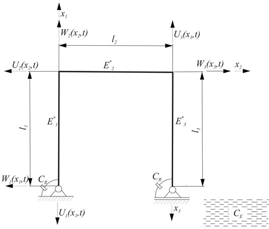
2. Physical model of the system
In adopted model, illustrated in Fig. 1, the energy dissipation is the consequence of resistance to motion in frame supports , viscoelastic material of frame and medium surrounding the system (still fresh water).
Fig. 1Scheme of the considered system
3. Mathematical model and boundary problem
Basis on the Hamilton’s principle the boundary problem for Bernoulli-Euler beams was formulated:
where: – kinetic energy, – potential energy, – virtual work of non-conservative forces, – transverse displacements, – longitudinal displacements, – Young’s modulus, – cross-sectional areas, – moment of inertia in cross-sections, – length of the beams, – total length of frame, – material density, – spatial coordinate, – time, 1, 2, 3.
The continuity and geometrical boundary conditions are expressed as:
After placing to (1), Eq. (2)-(4) and taking into account the conditions Eq. (5), obtained the two equations of motion (in transversal and longitudinal direction):
and natural boundary conditions:
The Eqs. (6) and (7) are solved as follows:
Substitution of Eqs. (9) and (10) into Eqs. (6) and (7) leads to, respectively:
where:
The solution of Eqs. (11) and (12) are expressed in the form of functions:
where:
Introducing Eqs. (14) and (15) to boundary conditions Eqs. (5) and (8) leads to homogeneous set of equations ( – unknown constants), which can be written as matrix:
where:
If the determinant of the coefficient matrix equals to zero, considered system has a non-trivial solution (complex eigenvalues ), in form:
4. Parameters of the system
Computations were carried out for the parameters: beams length 1-4 [m]; 2 [m]; 1-4 [m]; beams diameter 0.05 [m]; Young modulus 2.1e11 [Pa]; material density 7.7e3 [kg/m3].
The damping parameters have the following non–dimensional form.
For internal damping:
For constructional damping:
For external damping:
For proportion between the length of the beams:
The main impact on damped vibration frequency and on amplitude decay factor have the values of from 0 to 2 (see [9, 10]). The value of of homogeneous steel was selected according to data from works [11-13]. External damping comes from viscous medium surrounding the considered frame. Value of external damping of still fresh water is 1.0041e(-3) [Ns/m2] or 0.49e(-6) [11, 12, 14].
5. Results
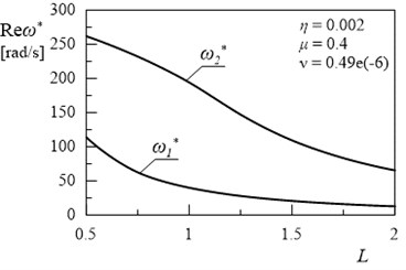
The effect of the computations are presented in 2D and 3D graphs on Figs. 2-16. In Fig. 2. the first two natural frequencies of the frame () and () in relation to length are illustrated. Presented relationships are the reference results. The comparison of undamped system (Fig. 2) with damped system (Fig. 3) confirmed that, described the damped vibration frequency and described the amplitude decay factor. Changes between the value of real part of the first two eigenvalues and the value of first two natural frequencies derived from movement resistance in the supports of frame.
Fig. 2Dependency between first two natural frequencies of frame and length L (η= 0, μ= 0, ν= 0)
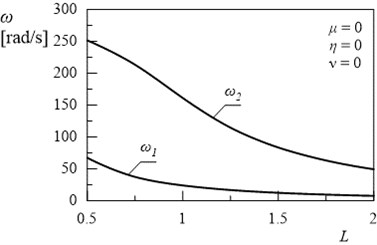
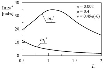
Fig. 3Dependency between first and second eigenvalue and length L (η= 0.002, ν= 0.49e(-6), μ= 0.4)
a)
b)
The aim of this paper was to analyze of an influence of different kinds of damping on vibration of portal frame. The effect of changes the geometrical parameters on eigenvalues of damped system were also examined. To compare the influence of external, internal and constructional damping on frame eigenvalues calculations were conducted and relationships between damping coefficients and length of beams modelled frame have been determined.
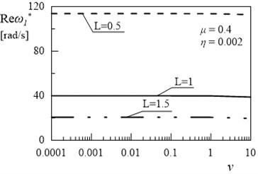
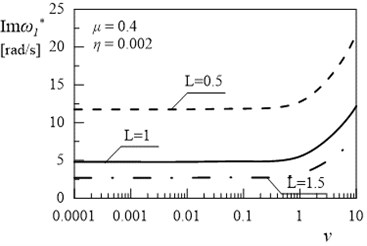
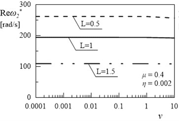
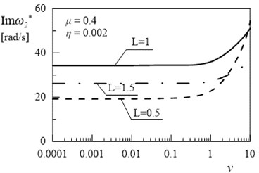
Figs. 4-7 illustrated the influence of simultaneous changes in the length and constructional damping coefficient on eigenvalues of considered system.
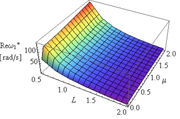
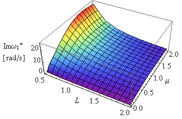
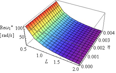
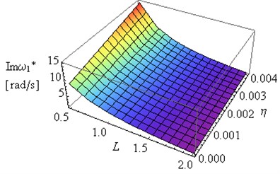
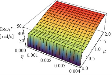
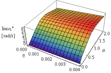
Fig. 4Influence of L and coefficient μ on Reω1* and Imω1* (η= 0.002, ν= 0.49e(-6))
a)
b)
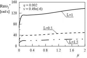
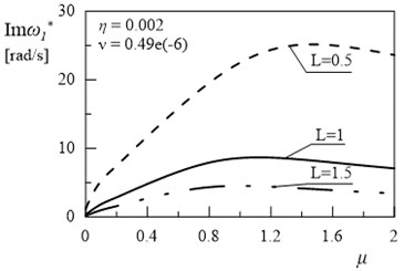
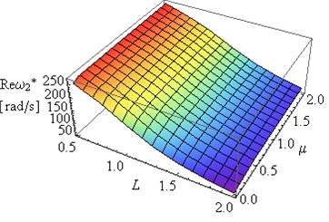
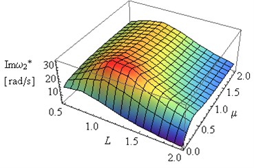
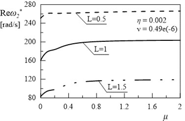
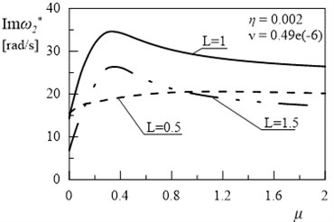
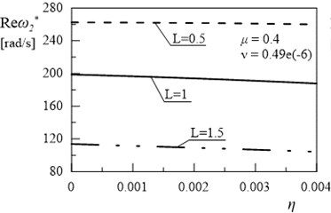
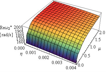
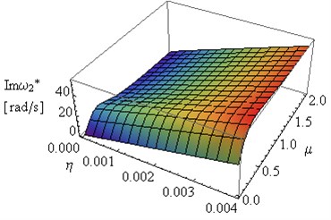
In Figs. 5 and 7 can be observed some substantial changes in the amplitude decay factor of first and the second eigenvalue with changes the value of coefficient . The imaginary part increasing to maximum values, for selected values of and , followed by 0 when (Figs. 4-7). Changes in illustrated in Figs. 4 and 6 are induced by the intervention in boundary conditions of system. When the value of coefficient is the highest the resistance and friction in the support (caused by a high value of viscous resistance) “locked” the rotary motion. On the three-dimensional graphs presented below the transition from joint mountings to rigid mountings can be observed.
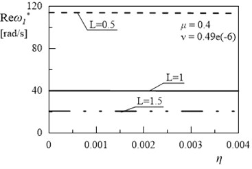
Fig. 5Dependency between first eigenvalue and coefficient µ (η= 0.002, ν= 0.49e(-6))
a)
b)
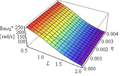
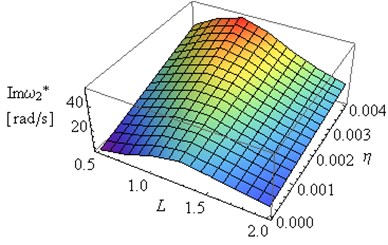
Fig. 6Influence of L and coefficient μ on Reω2* and Imω2* (η= 0.002, ν= 0.49e(-6))
a)
b)
Fig. 7Dependency between second eigenvalue and coefficient μ (η= 0.002, ν= 0.49e(-6))
a)
b)
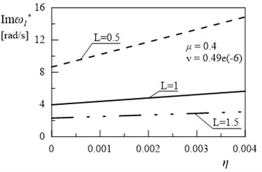
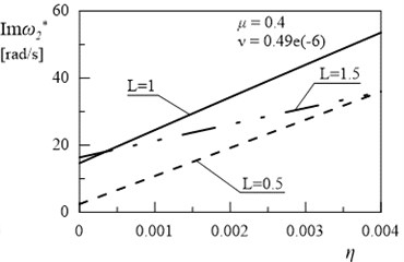
Figs. 8-11 presents the results of the investigations of relationships between the first eigenvalue of the frame and internal damping coefficient . Introduction of the internal damping to considered system has insignificant influence on the first and the second damped vibration frequency (Figs. 9 and 11). Significant changes can be observed in and with changes the value of coefficient (Figs. 8-11). The increase in the values of amplitude decay factor throughout the investigated range is caused by higher values of coefficient .
Fig. 8Influence of L and coefficient η on Reω1* and Imω1* (μ= 0.4, ν= 0.49e(-6))
a)
b)
Fig. 9Dependency between first eigenvalue and coefficient η (μ= 0.4, ν= 0.49e(-6))
a)
b)
Fig. 10Influence of L and coefficient η on Reω2* and Im(ω2*) (μ= 0.4, ν= 0.49e(-6))
a)
b)
Fig. 11Dependency between second eigenvalue and coefficient η (μ= 0.4, ν= 0.49e(-6))
a)
b)
The obtained results helps to determine the proportion between the length of the beams for which the amplitude decay factor reaches the maximum value. Fig. 12 and 13 illustrated the dependency between the coefficient and and of the first and the second eigenvalue for frame. Only high value of external damping has significant effects on values of imaginary part of solution. Influence of coefficient on damped frequency in Figs. 12 and 13 is similar to influence of coefficient on in Figs. 9 and 11.
The comparison of the effect of complex damping on frame eigenvalues, leads to the conclusion, that the main influence on vibration amplitude has the values of constructional damping coefficient (Figs. 4-7). The progression of function , with changes the value of coefficient , illustrated in Figs. 14 and 15 confirms that assumption.
Fig. 12Dependency between first eigenvalue and coefficient ν (μ= 0.4, η= 0.002)
a)
b)
Fig. 13Dependency between second eigenvalue and coefficient ν (μ= 0.4, η= 0.002)
a)
b)
Fig. 14Influence of coefficients μ and η on Reω* and Imω1* (L= 2, ν= 0.49e(-6))
a)
b)
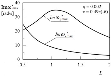
The higher value of then the amplitudes of vibration are more damped, as can be seen in the all above figures. In Fig. 16 the maximum values of amplitude decay factor for the two first modes of vibration in the examined system depending on the length are presented.
Fig. 15Influence of coefficients μ and η on Reω2* and Imω2* (L= 2, ν= 0.49e(-6))
a)
b)
Fig. 16Dependency between the Im(ωmax*) and the length L (for η= 0.002, ν= 0.49e(-6))
6. Conclusions
In this paper, the influence of internal, external and constructional damping on vibration of portal frame have been examined. The results presented in work shown, that taken into consideration the dissipation of vibration energy (as a result of different types of damping) to the mathematical model of vibrations of portal frame, causes substantial influence on the damped frequencies and vibration amplitude of the considered system. The density of medium surrounding the system has significant influence on values of amplitude decay factor and high value of external damping coefficient leads to the increasing of . The still fresh water resistance has a minor impact of frame vibration. The increase in the value of internal damping coefficient causes considerable increase in the amplitude decay factor while the insignificant changes in the damped frequency can be observed. The comparison of the effect of complex damping on frame eigenvalues, leads to the conclusion, that the main influence on vibration amplitude of investigated system was exerted the constructional damping. Changes between the value of real part of the first two eigenvalues and the value of first two natural frequencies derived from movement resistance – the rotary motion in supports is locked and the transition from joint to rigid mountings can be observed.
The obtained results helps determine the geometric parameters of frame and values of the damping coefficients for which the minimum vibration amplitudes in the system are maintained i.e. helps to determine the proportion between the length of the beams L for which the amplitude decay factor reaches the maximum value. The method described in this work could be useful as an additional design tool for engineers to modelled multi-bar systems with minimal vibrations amplitude. Based on the obtained results it is also possible to reduce the amplitude of vibration using rotational viscous dampers.
References
-
Szmidla J. Free vibrations of a Γ type planar frame loaded by a follower force directed towards the positive pole. Vibrations in Physical Systems, Vol. 24, 2010, p. 405-410.
-
Szmidla J. Vibrations and stability of T-type frame loaded by longitudinal force in relation to its bolt. Thin-Walled Structures, Vol. 45, 2007, p. 931-935.
-
Grossi R. O., Albarracín C. M. Vibrations of elastically restrained frames. Journal of Sound and Vibration, Vol. 285, Issues 1-2, 2005, p. 467-476.
-
Ratazzi A. R., Bambill D. V., Rossit C. A. Vibrations of a frame structure with a crack. Mecánica Computacional, Vol. 32, 2013, p. 3563-3574.
-
Mamatha Y. P., Sujith Kumar S., Vivek G., Sumanth D. R., Vinay N. Analysis of crack influence on an open frame L-structure using FEM. International Journal of Engineering Research and General Science, Vol. 4, Issue 4, 2016, p. 108-117.
-
Sokół K. Linear and non-linear vibrations of a column with an internal crack. Journal of Engineering Mechanics, Vol. 140, Issue 5, 2014, https://doi.org/10.1061/(ASCE)EM.1943-7889.0000719.
-
Grossi R. O., Albarracín C. M. Variational approach to vibrations of frames with inclined members. Applied Acoustics, Vol. 74, 2013, p. 325-334.
-
Lin H. P., Ro J. Vibration analysis of planar serial-frame structures. Journal of Sound and Vibration, Vol. 262, 2003, p. 1113-1131.
-
Sochacki W., Bold M. Transverse and longitudinal damped vibration of the GAMMA type frame. Journal of Applied Mathematics and Computational Mechanics, Vol. 15, Issue 2, 2016, p. 147-155.
-
Bold M., Sochacki W. Damped vibrations of the Γ type frame with open cracks. Journal of Vibroengineering, Vol. 20, Issue 1, 2018, p. 215-224.
-
Friswell M. I., Lees A. W. The modes of non-homogeneous damped beams. Journal of Sound and Vibration, Vol. 242, Issue 2, 2001, p. 355-361.
-
Kirrllov O. N., Seyranin A. O. The effect of small internal and external damping on the stability of distributed non-conservative systems. Journal of Applied Mathematics and Mechanics, Vol. 69, 2005, p. 529-552.
-
Liang J. W., Feeny B. F. Identifying Coulomb and viscous friction from free vibration decrements. Nonlinear Dynamics, Vol. 16, 1998, p. 337-347.
-
Yang Y.-R., Zhang J.-Y. Frequency analysis of a parallel at plate-type structure in still water. Part I: a multi-span beam. Journal of Sound and Vibration, Vol. 203, 1997, p. 795-804.
About this article

