Abstract
Based on the bending deformation theory of cantilever beam, the mathematical model of bending deformation of single valve slice under uniform load is proposed and deduced by using the microbeam element method (MEM). The accuracy and reliability of the mathematical model established by the MEM and the small deflection method (SDM) are verified through the finite element simulation comparison. The results show that the valve slice deformation mathematical model under uniform load established by using the deformation theory of the MEM is suitable not only for the small deflection deformation (SDD) but also for the large deflection deformation (LDD) of the valve slice, and can reflect the dynamic deformation characteristics of the valve slice more truly than the SDM, which provides a certain theoretical basis for the deformation study of single valve slice. At the same time, the mathematical model is used to simulate the deformation law of the valve slice when the thickness, inner radius and outer radius change. The conclusion provides technical support for the design and performance prediction of the shock absorber.
Highlights
- A method of "solving the deformation of the single valve slice by microbeam element" is proposed based on the bending deformation theory of cantilever beam, and the bending deformation expression of single valve slice of shock absorber is derived.
- Compared the MEM and SDM results with the finite element simulation results, the MEM which is suitable for solving both the SDD and LDD is explored.
- No matter the valve slice belongs to a SDD or LDD, the radial deformation calculated by MEM is closer to the FEM than SDM.
- Compared with SDM, the mathematical model of solving valve slice deformation by MEM is more accurate and reliable.
1. Introduction
The shock absorber is used to absorb the vibration from the road, and its performance directly affects the ride comfort and handling stability of the vehicle [1-5]. The vibration absorption performance of a shock absorber is determined by its damping characteristics, which is closely related to the deformation of the valve slice in the shock absorber valve system [6-7]. Therefore, it is particularly important to study the bending deformation of the valve slice of the shock absorber for the performance prediction and suspension damping matching [8-11].
How to accurately calculate the bending deformation of the valve slice will directly affect the accuracy of damping characteristics in the simulation model of the shock absorber [12]. At present, many scholars have carried out research on the deformation of shock absorber valve slices. For example, Panthi et al. established a mathematical model of the valve slice bending deformation by the energy method [13-14]. P. Czop et al. established a general solution expression for the bending deformation of the valve slice at any radius according to the thin disc theory [15-16]. Xu et al. obtained the analytical solution of the LDD of the annular valve based on Qian's perturbation method, but its coefficients must be fitted by finite element experiments [17]. Relatively speaking, the research on the bending deformation theory of the SDM is more in-depth, which has been applied in the deformation solution of the valve slice, but its limitation is that it is only suitable for the calculation of the small deflection deformation (SDD). In addition, there is no suitable analytical formula for the LDD of the valve slice [17-18].
To solve the above problems, a method of “solving the deformation of the single valve slice by microbeam element” is proposed based on the bending deformation theory of cantilever beam, and the bending deformation expression of single valve slice of shock absorber is derived. Comparing the MEM and SDM results with the finite element simulation results, the MEM which is suitable for solving both the SDD and LDD is explored. At the same time, by using this expression, the deformation law of throttle valve slice is obtained when the thickness, inner radius and outer radius change, which lays a theoretical foundation for the design and performance prediction of shock absorber in engineering practice.
2. Shock absorber model
2.1. Damping characteristics of the shock absorber
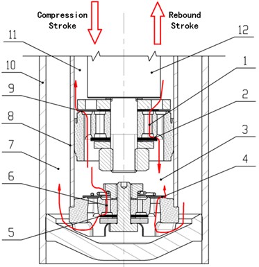
Fig. 1 shows the structure of an ordinary twin-tube hydraulic shock absorber. The reciprocating motion of the piston causes the oil to pass through the flow hole or throttling gap of the piston and bottom valve system to generate the damping force [19-23]. During the operation of the shock absorber, the suction valve 4 and the intake valve 9 can be opened only with a small oil pressure, while the rebound valve 2 and the compression valve 5 can be opened when the fluid reaches a certain pressure [24-25]. The opening of the rebound valve 2 and the compression valve 5 is directly related to the vibration velocity of the piston and determines the damping force of the shock absorber [2, 26-27].
Fig. 1Schematic diagram of the structure of the shock absorber valve system: 1 – rebound orifice, 2 – rebound valve, 3 – compression chamber, 4 – suction valve, 5 – compression valve, 6 – compression orifice, 7 – reservoir chamber, 8 – inner tube, 9 – intake valve, 10 – reservoir tube, 11 – rebound chamber, 12 – piston rod
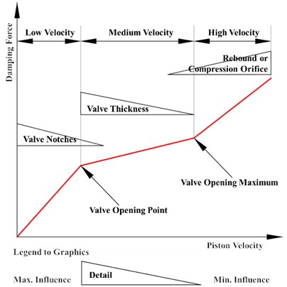
Under different vibration velocities of the piston, the structural parameters of the shock absorber valve systems have different effects on the damping force. Fig. 2 shows the influence and interaction of the main components of the valve system when the shock absorber works, including the degree of influence and contribution of each valve system component to the damping force, and the conclusions are as follows [12, 28-32]:
(1) When the vibration velocity of the piston is at a low velocity as shown in Fig. 2, the valve slice of the shock absorber valve system has not yet been opened, and the damping force of the shock absorber mainly depends on the number of valve slice notches of the valve system. With the increase of the piston vibration velocity, the influence of the number of valve slice notches on the damping force gradually decreases. When the velocity increases to a certain value and the valve slice gradually opens, the influence of the number of notches on the damping force tends to zero.
(2) When the vibration velocity of the piston is at a medium velocity as shown in Fig. 2, the valve slice of the shock absorber valve system has opened, and the damping force mainly depends on the valve opening. The valve opening point and the valve opening depend on the equivalent thickness of the valve slice. With the increase of the piston vibration velocity, the effect of the equivalent thickness of the valve slice on the damping force gradually decreases. When the piston vibration velocity is lower than the “valve opening point” velocity or higher than the “valve opening maximum” velocity, the change of the equivalent thickness of the valve slice has no effect on the damping force.
(3) When the vibration velocity of the piston is at a high velocity as shown in Fig. 2, the shock absorber valve system has opened to the maximum. The damping force mainly depends on the circulation area of the rebound orifice 1 or the compression orifice 6. With the increase of the piston vibration velocity, the influence of the circulation area of the rebound orifice 1 or the compression orifice 6 on the damping force of the shock absorber increases, and the circulation area also determines the slope of the damping characteristic curve in the high-velocity region.
Fig. 2Influence curve of valve system structural parameters on damping force
2.2. Determination of load range of the shock absorber valve slice
During the operation of the shock absorber, the internal oil pressure changes with the relative movement of the piston, and the bending deformation of the valve slice is generated by the oil pressure difference acting on the valve slice. Therefore, it is essential to determine the throttling pressure differential range of the valve slice in the shock absorber for the deformation analysis of the valve slice [33-35].
Fig. 3Mechanical model of valve slice: 1 – valve slice, 2 – limit washer, 3 – limit retaining ring, 4 – valve rod
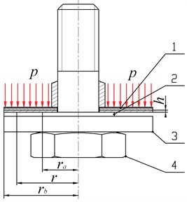
Mechanical model of valve slice as shown in Fig. 3, the valve system is composed of several valve slices superimposed, and a limit washer 2 is arranged between the superimposed valve slices 1 and the limit retaining ring 3. The function of the limit washer 2 is to support the valve slice when it is deformed, and the other is to limit the deformation opening of the valve slice to prevent the valve slice from being damaged by excessive deformation.
The thickness of the limit washer 2 is generally 0.3 mm, so the maximum deformation of the valve slice will not exceed the thickness of the limit washer 2. The thickness of each valve slice constituting the damper valve system is generally 0.2-0.3 mm. Therefore, the FEM is used to simulate the equivalent maximum load when the deformation range of a single valve slice is 0.3 ~0.4 mm. The simulation cloud diagram is shown in Fig. 4 and Fig. 5, the parameters and the simulation results are shown in Table 1.
Fig. 4Maximum opening of the thickness of valve slice is 0.2 mm
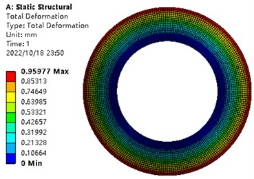
Fig. 5Maximum opening of the thickness of valve slice is 0.3 mm
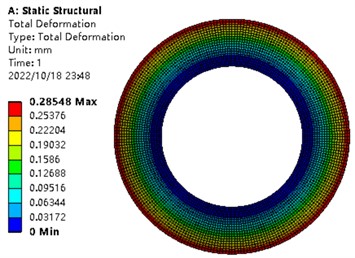
Table 1The parameters and maximum deformation of the valve slice
Inside radius (mm) | Outer radius (mm) | Young’s modulus (GPa) | Poisson’s ratio | Thickness (mm) | Load (MPa) | Maximum deformation (mm) |
6 | 10 | 200 | 0.3 | 0.2 | 4 | 0.95977 |
6 | 10 | 200 | 0.3 | 0.3 | 4 | 0.28548 |
As can be seen from Table 1, for a single valve slice of 0.2-0.3 mm, if it bears a load of 4 MPa, its maximum opening is about 0.28548-0.95977 mm. Therefore, the load borne by a single valve slice of 4 MPa is selected as the study load below.
3. Solving the deformation of a single valve slice with the MEM
3.1. Microbeam element deformation model
The annular valve slice of the shock absorber can be regarded as being surrounded by many microbeam elements, as shown in Fig. 6 [17]. Its inner radius is , outer radius is , and the thickness is . Its length is the difference between the outer and inner radii, and the angle between the two sides of the microbeam element is . When the valve slice is subjected to a uniform load, each section of microbeam element is subjected to the same force, and the deformation of each section of microbeam element in the radius direction is consistent. According to the theory of elasticity, the side force between two adjacent beams can be ignored, and the deformation in the radial direction is also the same. Therefore, the deflection deformation of the annular valve can be transformed into solving the deformation of the microbeam element shown in Fig. 7.
3.2. Mathematical model of a single valve slice microbeam element deformation
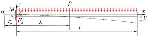
Since the inner end of the valve slice is fixed and the outer end is freely constrained, the microbeam element in Fig. 7 can be equivalent to the micro cantilever beam in Fig. 8 [14]. During the deformation of the shock absorber valve slice, its upper surface is subjected to a uniform load . Its inner radius is , the outer radius is , and the height is .
The coordinate system as shown in Fig. 8 is established, which takes point as the origin. The distance from the origin to the fixed end is , and the length of the micro cantilever beam is .
Fig. 6Taking microbeam element on the valve slice
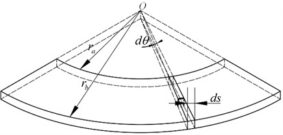
Fig. 7Microbeam element
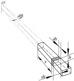
Fig. 8Schematic diagram of the micro cantilever beam
3.2.1. Solving moment of the micro cantilever beam at any location
The force on the micro cantilever beam at any position is:
The position of the force acting point is:
The moment of the force acting on the micro cantilever beam at the position is:
3.2.2. Listing and integrating the approximate differential equations of the deflection curve
According to the engineering mechanics, the approximate differential equation of the deflection curve of the micro cantilever beam can be obtained [36], i.e.:
The inertia moment of the section at the location is:
Combined Eqs. (1-5), we can get:
Integrate both sides of the Eq. (6) with respect to , so:
where is the integral constant.
Integrate both sides of the Eq. (7) with respect to x and merge the similar terms, so:
where is the integral constants.
3.2.3. Determining the integral constant
According to the actual constraints of the valve slice, the deflection and rotation angle of the micro cantilever beam at the fixed end are zero, so:
Combined Eq. (7-9), so 0 and 0.
3.2.4. Determining the angle equation and deflection equation
Substituting and into Eq. (7) and Eq. (8), the angle equation and the deflection equation of the micro cantilever beam are:
Since, , Eq. (11) can be transformed into:
Therefore, Eq. (12) is the annular valve slice bending deformation expression under the uniform load.
4. Solving the deformation of a single valve slice with the SDM
4.1. Mechanical model of the SDD of the single valve slice
The valve system structure of the shock absorber mostly adopts the superposition form of multiple annular thin valve slices. After the valve slice is assembled with the piston or bottom valve seat, the valve slice of the shock absorber can be simplified into an annular thin disc with a fixed inner edge and a free outer edge, which is subjected to a uniform load. The valve slice of the shock absorber can be simplified as shown in Fig. 3 if only the single valve slice is considered. The uniform load on the valve slice is , the thickness is , the inner circle of the valve slice is fixed, and the outer circle is free. The inner radius of the valve slice is , the outer radius is , and is the radius at any point between the inner and outer circles.
4.2. Mathematical model of the SDD of a single valve slice
Because the structure and the load of the annular valve slice shown in Fig. 3 are symmetrical around the central axis, a polar coordinate system with the center of the valve slice as the pole was established. According to the theory of elastic mechanics, the differential equation of the bending deformation of the thin elastic valve slice can be obtained, as follows [15-16, 37]:
where is the Young’s modulus of the valve slice, is the Poisson’s ratio, is the thickness, is the radius and .
The general solution expression of Eq. (13) is:
where is the special solution of the differential equation, , , , and are constants, depending on the boundary conditions.
When , the boundary conditions are as follows.
The deformation of the inner circle is equal to zero, i.e. , so:
The deformation slope of the inner circle is equal to zero, i.e. , so:
The bending moment expression at the outer circle is:
The bending moment at the outer circle is zero, i.e. , so:
The shear force expression at the outer circle is:
The shear force at the outer circle is equal to zero, i.e. , so:
According to Eq. (15-18), we can get:
Eq. (19) can be deformed as follows:
where:
The Eq. (20) was solved using MATLAB software, and the value of , , , and was obtained. Substituting these parameters into Eq. (14), the bending deformation expression of the valve slice can be obtained.
5. Stress mathematical model of a single valve slice
The internal moments of the annular valve slice in the shock absorber are mainly the radial bending moment and circumferential bending moment . According to the theory of elastic mechanics, the internal moments and of the valve slice can be expressed as [38-39]:
According to the theory of elastic mechanics, the stress on the upper and lower surfaces (/2, is the axial position coordinate of the valve slice) at the location of the valve slice is the largest. According to the relationship between stress and internal force, the radial stress and circumferential stress of the upper and lower surfaces at the location of the valve slice can be obtained [39]:
The valve slice is mainly subjected to the radial and circumferential stress, according to the fourth strength theory, the compound stress of the valve slice is [39]:
6. Validation of the mathematical model of the valve slice
To verify the correctness of the above mathematical model, the deformation of the valve slice is simulated by the FEM [1,14,17,33]. The finite element (FE) results are used to verify the results of the MEM and SDM. A FE model of a single valve slice is developed with the Static Structural of ANSYS Workbench. The inner radius end of the valve slice is fixed, and the outer radius end is free, and the parameters of the valve slice are listed in Table 2.
Table 2The parameters of the valve slice
Parameter | Value (units) | Parameter | Value (units) |
Inner radius | 6 mm | Young’s modulus | 200 GPa |
Outer radius | 10 mm | Poisson’s ratio | 0.3 |
thickness | 0.3 mm |
6.1. Simulation and comparison of valve slice deformation along the radius direction
Uniform loads of 4 MPa, 1 MPa, and 0.5 MPa are applied to the valve slice, respectively, and the mesh was divided on the model surface. The deformation of the valve slice along the radius direction is analysed, and the simulation cloud diagram of the deformation and the stress of the valve slice under a load of 4.0 MPa are shown in Fig. 5 and Fig. 9, respectively.
Table 3Maximum deformation and error comparison of the outer end of the valve slice
Load | Item | Method | ||
FEM | MEM | SDM | ||
4 MPa | Maximum deformations (mm) | 0.2855 | 0.2844 | 0.2182 |
Error | 0.39 % | 23.57 % | ||
1 MPa | Maximum deformations (mm) | 0.0714 | 0.0711 | 0.0546 |
Error | 0.42 % | 23.53 % | ||
0.5 MPa | Maximum deformations (mm) | 0.0357 | 0.0356 | 0.0273 |
Error | 0.28 % | 23.53 % | ||
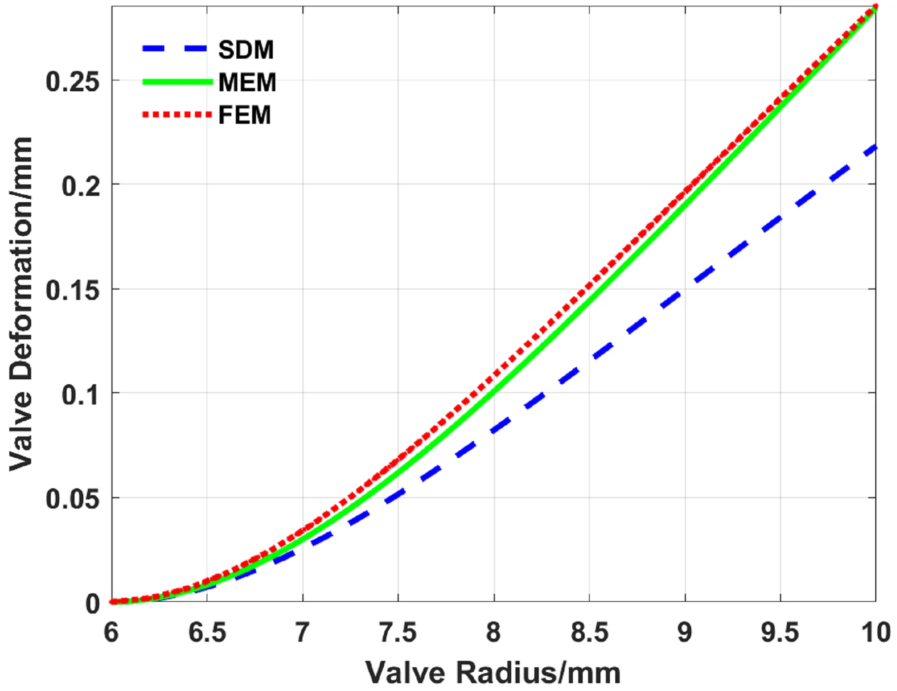
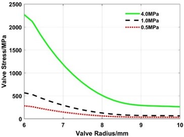
The radial deformation curves of the valve slice are shown in Fig. 10-Fig. 12, respectively, and the stress change curve is shown in Fig. 13. The maximum deformations and error of the outer end of the valve slice are calculated with the FEM, MEM, and SDM, as listed in Table 3.
Fig. 9Stress simulation cloud diagram of valve slice
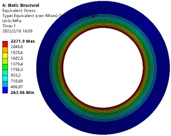
Fig. 10Radial deformation of the valve slice under load of 4.0 MPa
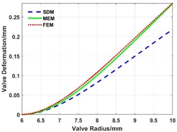
Fig. 12Radial deformation of the valve slice under load of 0.5 MPa
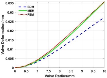
Fig. 11Radial deformation of the valve slice under load of 1.0 MPa
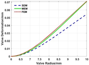
Fig. 13Radial stress of the valve slice
The following results can be obtained from Fig. 10 to Fig. 13 and Table 3.
(1) The deformation calculated with the FEM, MEM, and SDM have the same change trend along the radius direction.
(2) Compared with the deformation of the three loads in Table 3, the maximum error between the MEM and FEM is 0.42 %, while the maximum error between the SDM and FEM is 23.57 %.
(3) The maximum deformation in Fig. 10 is 0.2855 mm, and it is much greater than 1/5 of the thickness of the valve slice. The maximum stress calculated with FEM in Fig. 13 is 2271.9 MPa, so the valve slice is subject to the LDD under 4.0 MPa.
(4) When the load is 1.0 MPa and 0.5 MPa, the maximum deformation of the valve slice is close to and less than 1/5 of the thickness, and the maximum stress of the valve slice is far less than 1000 MPa. Hence, the valve slice belongs to the SDD.
From the above calculation and simulation results, whether the valve slice belongs to the SDD or not, the radial deformation of the valve slice calculated by the MEM is closer to the results of the FEM than the SDM.
6.2. Law analysis of the maximum deformation of the valve slice with thickness change
Keeping the inner radius and outer radius of the valve slice unchanged, uniform loads of 4.0 MPa, 1.0 MPa, and 0.5 MPa are applied on the valve slice. The variation trend curve of the maximum deformation at the outer end of the valve slice is simulated by FEM, MEM, and SDM when the thickness changes between 0.1-0.5 mm, as shown in Fig. 14 to Fig. 16. The curve of maximum stress calculated with the FEM changes with the thickness is shown in Fig. 17. The maximum deformations of the valve slice when the thickness is 0.1 mm are calculated with the FEM, MEM, and SDM, as listed in Table 4.
Fig. 14Maximum deformation of the valve slice at different thicknesses (load: 4.0 MPa)
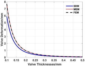
Fig. 15Maximum deformation of the valve slice at different thicknesses (load: 1.0 MPa)
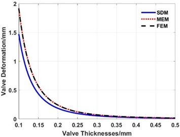
Fig. 16Maximum deformation of the valve slice at different thicknesses (load: 0.5 MPa)
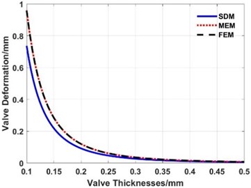
Fig. 17Maximum stress of the valve slice at different thicknesses
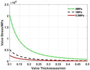
Table 4The maximum deformation and error of the valve slice with the thickness of 0.1 mm
Load | Item | Method | ||
FEM | MEM | SDM | ||
4 MPa | Maximum deformations (mm) | 7.6603 | 7.6800 | 5.8927 |
Error | 0.26 % | 23.07 % | ||
1 MPa | Maximum deformations (mm) | 1.9151 | 1.9200 | 1.4732 |
Error | 0.26 % | 23.07 % | ||
0.5 MPa | Maximum deformations (mm) | 0.9575 | 0.9600 | 0.7366 |
Error | 0.26 % | 23.07 % | ||
From Fig. 14 to Fig. 17 and Table 4, the following conclusions can be drawn:
(1) The deformation calculated with the FEM, MEM, and SDM have the same change trend when the thickness of the valve slice changes.
(2) Comparing the deformations under the three loads in Table 3, the maximum error between the MEM and FEM is 0.26 %, while the maximum error between the SDM and FEM is 23.07 %.
(3) When the thickness of the valve slice is 0.1 mm, the maximum deformation is much greater than 1/5 of the thickness and even reaches 6-8 mm, which is out of the engineering practice. The maximum stress of the valve slice calculated with the FEM in Fig. 17 is much greater than 1000 MPa, so the valve slice has LDD at this thickness.
From the above calculation and simulation results, whether the valve slice belongs to the SDD or not, the maximum deformation of the valve slice at different thicknesses calculated with the MEM is closer to the results of the FEM than the SDM.
6.3. Law analysis of the maximum deformation of the valve slice change with the load
The inner radius and outer radius of the valve slice are not changed, and the thickness of the valve slice is 0.3 mm. The FEM, MEM, and SDM are used to calculate the variation trend curve of the valve slice deformation when the load changes between 0-4.0 MPa, as shown in Fig. 18. The stress of the valve slice calculated with FEM is shown in Fig. 19.
Fig. 18Influence of the valve load on the maximum deformation of the valve slice
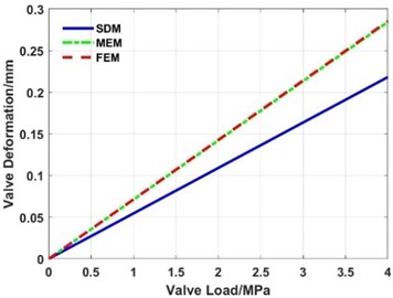
Fig. 19Influence of the valve load on the maximum stress of the valve slice
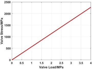
From Fig. 18-Fig. 19, the maximum deformation and maximum stress of the valve slice increase linearly with the increase of the load when the thickness is constant. No matter whether the valve deformation is the SDD or LDD, the deformation calculated with the MEM is basically the same as that of the FEM, while the deformation of the SDM has a larger error with that of the FEM.
7. Effect of the inner and outer radii of the valve slice on the deformation
To better provide theoretical support for shock absorber design and performance prediction, the law of maximum deformation and stress of the valve slice changes with the inner and outer radii is studied with the above-mentioned mathematical models of the MEM and SDM, and the results were compared with those of the FEM when the load is constant.
7.1. Effect of the outer radius on the deformation
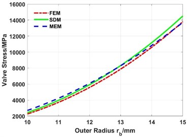
When the thickness of the valve slice is 0.3 mm, the load is 4.0 MPa, the inner radius is constant, and the outer radius varies from 10 mm to 15 mm, the deformations are shown in Fig. 20 and Fig. 21. The following results can be obtained:
(1) The maximum deformation increases exponentially with the increase of the outer radius.
(2) The deformation calculated by the MEM is in good agreement with the simulation results of the FEM, while the absolute difference between the deformation of the SDM and FEM increases with the increase of the outer radius.
(3) The maximum stress also increases with the increase of the outer radius.
Fig. 20Influence of the outer radius on the maximum deformation of the valve slice
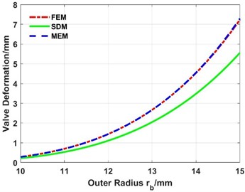
Fig. 21Influence of the outer radius on the maximum stress of the valve slice
7.2. Effect of the inner radius on the deformation
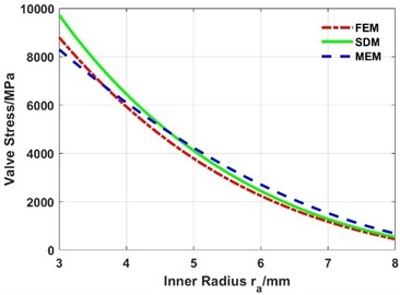
When the outer radius is constant and the inner radius varies from 3 mm to 8 mm, the deformations are shown in Fig. 22 and Fig. 23. It can be seen that:
(1) The maximum deformation decreases exponentially with the increase of the inner radius.
(2) The deformation calculated by the MEM is in good agreement with the simulation results of the FEM, while the absolute difference between the deformation of the SDM and FEM decreases with the increase of the inner radius.
(3) The maximum stress decreases with the increase of the inner radius.
Fig. 22Influence of the inner radius on the maximum deformation of the valve slice
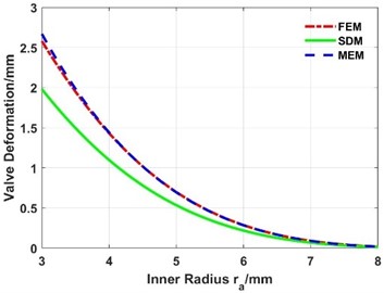
Fig. 23Influence of the inner radius on the maximum stress of the valve slice
8. Discussion
Factors such as oil temperature, oil viscosity, oil flow characteristics, internal wear of the shock absorber, parts manufacturing accuracy and assembly accuracy will affect the deformation of the valve slice. In order to reduce the complexity of the mathematical model, this paper assumes that the above factors remain unchanged when the valve slice is deformed, while the changes of the above factors are inevitable when the shock absorber is working. In particular, the single valve slice is more susceptible to the above factors than the superimposed valve slice. Although the calculation results of the mathematical model established under the premise of assumptions in this paper are in good agreement with the simulation results of the FEM, for academic rigor, the mathematical model in this paper needs to be tested continuously in future practical applications, and the influence degree of the assumed constant factors on the calculation results is summarized.
9. Conclusions
Based on the structure and working principle of the shock absorber valve system, the damping characteristics of the shock absorber are analysed and the pressure differential range of the valve slice is determined. The theoretical mathematical models of the SDM and MEM are developed, and the accuracy of the theoretical mathematical models are verified with FEM. The main conclusions are summarized as follows:
1) The change trend of the deformation calculated by the SDM and MEM is consistent with that of the FEM in the radius direction. The maximum error between the MEM and FEM is 0.42 %, while the maximum error between the SDM and FEM is 23.57 %.
2) When the thickness of the valve slice changes, the change trend of the deformation calculated with the SDM, MEM, and FEM is consistent. The maximum error between the MEM and FEM is 0.26 % when the thickness of the valve slice is 0.1 mm, while the maximum error between the SDM and FEM is 23.07 %.
3) When the load of the valve slice increases, the maximum deformation of the valve slice increases linearly, the simulation results of the MEM and FEM are consistent, while the deformation of the SDM is highly different from the deformation of the FEM.
4) The maximum deformation of the valve slice increases exponentially with the increase of the outer radius. The absolute difference between the deformation of the SDM and FEM increases with the increase of the outer radius, while the deformation calculated with the MEM coincides well with the FE result.
5) The maximum deformation of the valve slice decreases exponentially with the increase of the inner radius. The absolute difference between the deformation calculated with the SMD and FEM decreases with the increase of the inner radius, while the deformation calculated with the MEM is in good agreement with the FE result.
The above calculation and simulation results show that no matter whether the valve slice belongs to the SDD or LDD, the radial deformation of the valve slice calculated with the MEM is closer to the FEM than SDM, indicating that compared with the SDM, the mathematical model of the MEM to solve the deformation of the valve slice is more accurate and reliable, which provides a theoretical basis and technical support for the design and performance prediction of the shock absorber.
The above calculation and simulation results show that no matter the valve slice belongs to a SDD or LDD, the radial deformation calculated by MEM is closer to the FEM than SDM, indicating that compared with SDM, the mathematical model of solving valve slice deformation by MEM is more accurate and reliable, which provides a certain theoretical basis for the deformation study of single valve slice, and also provides technical support for the design and performance prediction of shock absorbers.
References
-
Q. Chen, Z. Xu, M. Wu, Y. Xiao, and H. Shao, “Study on dynamic characteristic analysis of vehicle shock absorbers based on bidirectional fluid-solid coupling,” Engineering Applications of Computational Fluid Mechanics, Vol. 15, No. 1, pp. 426–436, Jan. 2021, https://doi.org/10.1080/19942060.2021.1878059
-
F. Xie et al., “Temperature rise characteristics of the valve-controlled adjustable damping shock absorber,” Mechanics and Industry, Vol. 21, No. 1, p. 111, 2020, https://doi.org/10.1051/meca/2019084
-
A. Biradar, A. Patil, and K. K. Dhande, “Shock absorber design and analysis for off road race car,” Materials Today: Proceedings, Vol. 44, No. 6, pp. 4997–5003, 2021, https://doi.org/10.1016/j.matpr.2020.12.941
-
J. Łuczko and U. Ferdek, “Nonlinear dynamics of a vehicle with a displacement-sensitive mono-tube shock absorber,” Nonlinear Dynamics, Vol. 100, No. 1, pp. 185–202, Mar. 2020, https://doi.org/10.1007/s11071-020-05532-7
-
C. Graczykowski and R. Faraj, “Identification-based predictive control of semi-active shock-absorbers for adaptive dynamic excitation mitigation,” Meccanica, Vol. 55, No. 12, pp. 2571–2597, Dec. 2020, https://doi.org/10.1007/s11012-020-01239-6
-
Q. Zhang, Z. Yang, C. Wang, Y. Yang, and R. Zhang, “Intelligent control of active shock absorber for high-speed elevator car,” Proceedings of the Institution of Mechanical Engineers, Part C: Journal of Mechanical Engineering Science, Vol. 233, No. 11, pp. 3804–3815, Jun. 2019, https://doi.org/10.1177/0954406218810045
-
P. Czop and D. Sławik, “Fatigue model of a disc valve system used in shock absorbers,” International Journal of Heavy Vehicle Systems, Vol. 24, No. 4, p. 327, 2017, https://doi.org/10.1504/ijhvs.2017.087232
-
J. Zou, X. Guo, M. A. A. Abdelkareem, L. Xu, and J. Zhang, “Modelling and ride analysis of a hydraulic interconnected suspension based on the hydraulic energy regenerative shock absorbers,” Mechanical Systems and Signal Processing, Vol. 127, pp. 345–369, Jul. 2019, https://doi.org/10.1016/j.ymssp.2019.02.047
-
Q. Chen, M. Wu, S. Kang, Y. Liu, and J. Wei, “Study on cavitation phenomenon of twin-tube hydraulic shock absorber based on CFD,” Engineering Applications of Computational Fluid Mechanics, Vol. 13, No. 1, pp. 1049–1062, Jan. 2019, https://doi.org/10.1080/19942060.2019.1666035
-
J. Sehovic, I. Filipovic, and B. Pikula, “Experimental Determination of Non-Linear Characteristics of the Passenger Vehicle Suspension System,” Transactions of FAMENA, Vol. 44, No. 2, pp. 13–22, Jun. 2020, https://doi.org/10.21278/tof.44202
-
Y. Badri, T. Syam, S. Sassi, M. Hussein, J. Renno, and S. Ghаni, “Investigating the characteristics of a magnetorheological fluid damper through CFD modeling,” Materials Research Express, Vol. 8, No. 5, p. 055701, May 2021, https://doi.org/10.1088/2053-1591/abfcf6
-
V. Santos Arconada and J. García-Barruetabeña, “Development and validation of a simplified nonlinear dynamic model of a passive twin-tube hydraulic shock absorber,” Journal of Vibration and Control, Vol. 27, No. 15-16, pp. 1724–1735, Aug. 2021, https://doi.org/10.1177/1077546320947955
-
M. Alonso and A. Comas, “Thermal model of a twin-tube cavitating shock absorber,” Proceedings of the Institution of Mechanical Engineers, Part D: Journal of Automobile Engineering, Vol. 222, No. 11, pp. 1955–1964, Nov. 2008, https://doi.org/10.1243/09544070jauto829
-
V. Skrickij, D. Savitski, V. Ivanov, and P. Skačkauskas, “Investigation of cavitation process in monotube shock absorber,” International Journal of Automotive Technology, Vol. 19, No. 5, pp. 801–810, Oct. 2018, https://doi.org/10.1007/s12239-018-0077-1
-
P. Czop, D. Slawik, P. Śliwa, and G. Wszolek, “Simplified and advanced models of a valve system used in shock absorbers,” Journal of Achievements in Materials and Manufacturing Engineering, Vol. 33, No. 2, pp. 173–180, 2009.
-
P. Czop, D. Slawik, and P. Sliwa, “Static validation of a model of a disc valve system used in shock absorbers,” International Journal of Vehicle Design, Vol. 53, No. 4, p. 317, 2010, https://doi.org/10.1504/ijvd.2010.034104
-
J. Xu, J. Chu, and H. Ma, “Hybrid modeling and verification of disk-stacked shock absorber valve,” Advances in Mechanical Engineering, Vol. 10, No. 2, p. 168781401875639, Feb. 2018, https://doi.org/10.1177/1687814018756398
-
Y. Chen, K. Guo, Y. Yang, and Y. Zhuang, “Physical modeling of shock absorber using large deflection theory,” SAE International Journal of Passenger Cars – Mechanical Systems, Vol. 5, No. 1, pp. 393–403, Apr. 2012, https://doi.org/10.4271/2012-01-0520
-
P. Skačkauskas, V. Žuraulis, V. Vadluga, and S. Nagurnas, “Development and verification of a shock absorber and its shim valve model based on the force method principles,” Eksploatacja i Niezawodnosc – Maintenance and Reliability, Vol. 19, No. 1, pp. 126–133, Dec. 2016, https://doi.org/10.17531/ein.2017.1.18
-
J. Chacón, B. Boada, M. Boada, and V. Díaz, “Experimental study and analytical model of bleed valve orifice influence of a high-performance shock absorber on vehicle dynamics,” Advances in Mechanical Engineering, Vol. 9, No. 9, p. 168781401771900, Sep. 2017, https://doi.org/10.1177/1687814017719004
-
H. Liu et al., “Effect of air chamber and oil properties on damping characteristics of single-tube pneumatic shock absorber,” International Journal of Structural Integrity, Vol. 9, No. 1, pp. 27–37, Feb. 2018, https://doi.org/10.1108/ijsi-03-2017-0017
-
Q. Xiao, Q. Li, and C. Chang, “The influence of lateral shock absorber valve parameters on vehicle dynamic performance,” Journal of Mechanical Science and Technology, Vol. 29, No. 5, pp. 1907–1911, May 2015, https://doi.org/10.1007/s12206-015-0412-7
-
T. Funke and D. Bestle, “Physics-based model of a stroke-dependent shock absorber,” Multibody System Dynamics, Vol. 30, No. 2, pp. 221–232, Aug. 2013, https://doi.org/10.1007/s11044-013-9348-9
-
Z. Hryciów, “An investigation of the influence of temperature and technical condition on the hydraulic shock absorber characteristics,” Applied Sciences, Vol. 12, No. 24, p. 12765, Dec. 2022, https://doi.org/10.3390/app122412765
-
D. Buczkowski and G. Nowak, “Modelling the shock absorber piston valve using 2-way fluid-structure interaction,” Transport Problems, Vol. 16, No. 4, pp. 45–57, 2021, https://doi.org/10.21307/tp-2021-059
-
J. Zhao, P. K. Wong, X. Ma, and Z. Xie, “Design and analysis of an integrated sliding mode control-two-point wheelbase preview strategy for a semi-active air suspension with stepper motor-driven gas-filled adjustable shock absorber,” Proceedings of the Institution of Mechanical Engineers, Part I: Journal of Systems and Control Engineering, Vol. 232, No. 9, pp. 1194–1211, Oct. 2018, https://doi.org/10.1177/0959651818778217
-
L. M. Jugulkar, S. Singh, and S. M. Sawant, “Fluid flow modeling and experimental investigation on automobile damper,” Construction and Building Materials, Vol. 121, pp. 760–772, Sep. 2016, https://doi.org/10.1016/j.conbuildmat.2016.05.142
-
A. Alyukov, Y. Rozhdestvenskiy, and S. Aliukov, “Active shock absorber control based on time-delay neural network,” Energies, Vol. 13, No. 5, p. 1091, Mar. 2020, https://doi.org/10.3390/en13051091
-
S. Rieß, J. Hansmann, W. Kaal, and S. Herold, “High-frequency Characterization of Hydraulic Shock Absorbers,” ATZ worldwide, Vol. 121, No. 3, pp. 76–80, Mar. 2019, https://doi.org/10.1007/s38311-018-0224-3
-
D. Guan, X. Jing, H. Shen, L. Jing, and J. Gong, “Test and simulation the failure characteristics of twin tube shock absorber,” Mechanical Systems and Signal Processing, Vol. 122, pp. 707–719, May 2019, https://doi.org/10.1016/j.ymssp.2018.12.052
-
J. Zhao, P. K. Wong, Z. Xie, X. Ma, and X. Hua, “Design and control of an automotive variable hydraulic damper using cuckoo search optimized pid method,” International Journal of Automotive Technology, Vol. 20, No. 1, pp. 51–63, Feb. 2019, https://doi.org/10.1007/s12239-019-0005-z
-
B.-G. Kim, D.-S. Yoon, G.-W. Kim, S.-B. Choi, A. S. Tan, and T. Sattel, “Design of a novel magnetorheological damper adaptable to low and high stroke velocity of vehicle suspension system,” Applied Sciences, Vol. 10, No. 16, p. 5586, Aug. 2020, https://doi.org/10.3390/app10165586
-
Y. Chen, Y. Zhang, M. Xu, F. Du, and B. Li, “Mechanical modeling of local variable load and deform of valve slice,” in Advances in Intelligent Systems and Computing, pp. 773–780, 2020, https://doi.org/10.1007/978-3-030-34387-3_95
-
D. Buczkowski, S. Zymelka, and G. Nowak, “Experimental and numerical studies on the development of hysteresis in a shock absorber with a shim disc valve,” International Journal of Automotive and Mechanical Engineering, Vol. 19, No. 2, pp. 9747–9758, Jun. 2022, https://doi.org/10.15282/ijame.19.2.2022.10.0752
-
R. Hojjati-Talemi, A. Zahedi, and P. Baets, “Fretting fatigue failure mechanism of automotive shock absorber valve,” International Journal of Fatigue, Vol. 73, pp. 58–65, Apr. 2015, https://doi.org/10.1016/j.ijfatigue.2014.11.010
-
Y. K. Fu and B. Q. Dai, Engineering Mechanics. (in Chinese), Beijing: Beijing University of Aeronautics and Astronautics Press, 2016.
-
S. Li, Q. Yuan, Z. Xu, and C. Wu, “Outer characteristic simulation and performance analysis of variable shock absorber,” Journal of Vibroengineering, Vol. 20, No. 1, pp. 73–85, Feb. 2018, https://doi.org/10.21595/jve.2017.18450
-
A. Velychkovych, I. Petryk, and L. Ropyak, “Analytical study of operational properties of a plate shock absorber of a sucker-rod string,” Shock and Vibration, Vol. 2020, pp. 1–7, Jan. 2020, https://doi.org/10.1155/2020/3292713
-
Changcheng Zhou and Chengjun Li, “Analytic calculation of stress of multi-throttle-slices for twin tubes shock absorber,” in 2009 IEEE International Conference on Intelligent Computing and Intelligent Systems (ICIS 2009), pp. 84–88, Nov. 2009, https://doi.org/10.1109/icicisys.2009.5357930
Cited by
About this article

The study was supported by the Science and Technology Research Program of Chongqing Municipal Education Commission (Grant No. KJZD-K201803201).
The datasets generated during and/or analyzed during the current study are available from the corresponding author on reasonable request.
Shisheng Li: conceptualization, formal analysis, project administration, validation writing – original draft preparation. Qiong Yuan: data curation, methodology, resources, supervision, writing – review and editing.
The authors declare that they have no conflict of interest.
