Abstract
This paper presents a theoretical and finite element (FE) investigation of the generation and propagation characteristics of the fundamental Lamb waves symmetrical mode S0 and anti-symmetrical mode A0 after testing with different types of defects in the plates. The reflection and transmission of Lamb waves at a micro symmetry defect and asymmetry defect are analyzed numerically in the two-dimension (2D) model. Mode conversion of Lamb waves can occur upon encountering the asymmetry discontinuities leading to newly-converted modes apart from wave reflection and transmission. When testing the symmetry defects, the reflection and transmission waves have no modal separation phenomenon. To describe the mode conversion and reflection and transmission degree, and evaluate the micro defect severity, a series of defects are simulated to explore the relationships of defect reflection and transmission with the length and depth of a defect in the 2D FE model. In the three-dimension (3D) FE model, the straight-crest Lamb waves and circular-crest Lamb waves are simulated and researched by contrast analysis. Then the straight-crest Lamb waves are motivated to study the scattering laws of Lamb waves interacting with the circle hole defects and rectangular hole defects. S0 mode and SH0 mode are contained in the scattering waves after S0 mode testing the through holes defects. Corresponding mode energy percentages were analyzed at different micro defect severities changed in different ways. Simulation results illustrated that the modal energy percentages varied in a different character and provided support for the analytically determined results of Lamb waves in the non-destructive testing and evaluation.
Highlights
- In the two-dimension model, mode conversion of Lamb waves can occur upon encountering the asymmetry discontinuities leading to newly-converted modes apart from wave reflection and transmission.
- When testing the symmetry defects in the two-dimension model, the reflection and transmission waves have no modal separation phenomenon.
- In the three-dimension FE model, the straight-crest Lamb waves and circular-crest Lamb waves are simulated and researched by contrast analysis.
- When testing the through hole defects in the two-dimension model, S0 mode and SH0 mode are contained in the scattering waves after S0 mode testing the through holes defects.
1. Introduction
Lamb waves have been widely explored as a promising inspection tool for non-destructive testing (NDT) and structural health monitoring (SHM) during the past years [1, 2]. The development of computational finite element models for Lamb wave propagation and interaction is of great importance and offers an efficient nondestructive means in NDT and SHM. The advantages of Lamb waves include easily motivated, long-distance propagation, fastly and efficiently detection, and easily testing the shelter defects unreachable on the structures [3, 4]. It is widely used in detecting the defects in the plates. However, when it comes to highly corroded plates which have been used for many years, in which there are often numerous holes or cracks because of corrosion, the testing distance will be vitally influenced and shorten. Therefore, to learn the efficiency of Lamb wave testing on plates, it is of great necessity to carry on investigations of the interaction of Lamb waves with different combined defects.
Lamb waves are elastic waves belonging to special ultrasonic waves and propagate through the thin-plates or shell structures with free boundaries [5]. The received signal can engender complex reflection and transmission phenomenon and provide a lot of information after interacting with the defects in the plates [6]. The dispersion characteristic and multi-modal properties are two special propagation characteristics in plates. Therefore, further analysis of originally-generated and newly-converted Lamb modes is definitely required for better understanding of the mechanism of mode conversion and reflection and transmission after testing the micro defect, which is still limited on the defects testing application in the plates [7, 8]. The research of Lamb wave testing technology on defect assessment in plates is based on the principle that the incident Lamb mode would share its energy into several diffracted wave packets which depend on the location, geometry and dimension of the defects in the reflection and transmission mode.
Lamb waves were discovered by Horace Lamb [9] in 1917. Then Lamb wave was proposed to be used for defect detection. Many review articles have discussed the use of the Lamb waves in detecting the thinly metallic plates [10, 11]. Now, great progresses have been made in Lamb wave nondestructive testing technology in theoretical research, simulation research and experiment research. The theory studies of Lamb waves dispersion characteristics had been mature. Many studies about signal processing, such as Fourier transform and fast Fourier transform and short-time Fourier transform were conducted [12, 13]. Recent years, many optimization algorithms are adopted for digital signal processing in the NDT research to improve the defect detection accuracy. Deng studied some novel fault diagnosis methods based on integrating empirical wavelet transform and fuzzy entropy for motor bearing [14], EEMD and multi-scale fuzzy entropy for motor bearing [15], optimal LS-SVM with improved PSO algorithm [16, 17], CACO algorithm [18] and other heuristic optimization algorithms [19, 20]. These new improved algorithms [14, 21] showed a superior performance, and have been proved to be a potential useful tool in NDT research [22]. The improved algorithms [23] can obviously improve the convergence speed, and enhance the local search ability and global search capability for the signal processing and defect identification. Other researches have been studying about interaction of Lamb waves with damaged structures or discontinuities in such aspects as mode conversion, reflection and transmission characteristics [24, 25]. Different numerical methods were used, such as boundary element method [26], finite element method [27], finite difference method [28], and semi-analytical finite element method [29], these methods can provide multidimensional data for the signal processing and optimization algorithm design. Benz [30] studied the dispersion characteristics and multi-mode properties in groove plates using time-frequency analysis technology. Lu [31] studied the modal conversion rules of Lamb wave after testing the surface defects through the numerical and experimental methods. The propagation laws of Lamb waves influenced by the size of defect in composite materials were analyzed by Castaingse [31]. Feng [32] studied the scattering characteristics of Lamb wave in the plates with step-like discontinuities. Many other researches had shown the interactions with different types of defects including the hole defects, the surface defects, the vertical cracks, the inclined cracks, corrosion defects, groove defects and other irregular defects [33]. These authors combined a finite element method and a modal decomposition to investigate the interaction of Lamb waves with defects, but only considered a single characteristic or a single boundary condition. The Lamb waves diffraction on these defects is typically quite strong, leading to a considerable fraction of incident energy being reflected and transmitted, and to significant mode conversion in transmission. The defects and notches can be detected and identified by analyzing the Lamb waves modal content in reflected or transmitted displacement signals detected along the plate of interest. Due to the complex mode conversion and energy redistribution after testing the micro defects, Lamb wave’s scattering, reflection and transmission characteristics at the defects (or its interactions with the micro defects) is difficult to study in a pure analytical way. Numerical methods such as finite element method (FEM) about defect recognition depends on the systematically analysis of the dispersion characteristics, structural characteristics, attenuation characteristics, reflection and transmission characteristics after Lamb waves testing the defects in the plates, and the research about studying the sensitivity of each Lamb mode to the encountered defects is very important.
The present study in this paper is concerned with the current research situation and aims at investigating transient responses to the Lamb waves incidence and mode conversion coefficients in the case of weak interaction at micro defects, and at gaining insight in the factors determining the sensitivity of different types of Lamb modes to the geometrical characteristics of the micro defects and its surroundings. In particular, partial reflection and transmission of Lamb waves and the resonance behavior of the micro defects for the S0 mode and A0 mode incidence are analyzed by the finite element method and the results can easily be extrapolated to defects with higher contrast. In Section 2, The dispersion characteristics and wave structure characteristics are analyzed and the curves are drawn to provide theoretical support for numerical analysis. In Section 3, the 2D numerical results are showed to research the propagation, reflection and transmission characteristics after S0 mode and A0 mode Lamb waves testing the symmetrical and asymmetrical defects. In Section 4, the straight-crest Lamb waves are generated in 3D finite element model by comparison analysis. Corresponding mode energy percentages and scattering characteristics were analyzed emphatically by the straight-crest Lamb waves at different micro defect severities changed in different ways.
2. Lamb waves theory
There are two different kinds of Lamb waves in the plates including the straight-crest Lamb waves generated by point source and circular-crest Lamb waves generated by line source. According to the particle vibration characteristics in the plates, Lamb waves can be divided into symmetrical mode (S) and asymmetrical mode (A). Different modes can be generated under different phase velocity described with S0, S1, S2, S3, S4, ..., as well as A0, A1, A2, A3, A4, .... The vibration displacement of the material particles in the plate can be satisfied with Navier balance equation in the propagation of Lamb waves:
Here is the vector of particle vibration displacement, and is Lame constant, is the density, is the time.
The motion equation is solved using the potential function method base on the variational principle and the free boundary condition. The dispersion characteristic equations and wave structure equations of Lamb waves are deduced by the wave theory.
In the cartesian coordinate system, for symmetrical mode of straight-crest Lamb waves:
For anti-symmetrical modes of straight-crest Lamb waves:
In the cylindrical coordinate system, for symmetrical modes of circular-crest Lamb waves:
For anti-symmetrical modes of circular-crest Lamb waves:
Here the , , , , , is the phase velocity, is the group velocity, is the wave number, is angular frequency, and is the velocity of longitudinal wave and shear wave, is the thickness of the plate, is the Elastic Modulus, is the Poisson-Ratio, and and and and is the constant which can be solved by the free boundary condition. is the first kind zero-order Bessel function, is the vertical coordinate in the cartesian coordinate system, is the vertical coordinate in the cylindrical coordinate system, is diameter coordinate in the cylindrical coordinate system.
The Lamb waves equations show that these two kinds of Lamb waves have the same dispersion characteristic and same wave structure characteristic in thickness direction of plates. The distribution of circular-crest Lamb wave structure in the radius direction follow the distribution of Bessel function, and decrease with the diffusion area increases. Without considering the influence of material characteristics, the straight-crest Lamb waves have no energy attenuation in the propagation direction.
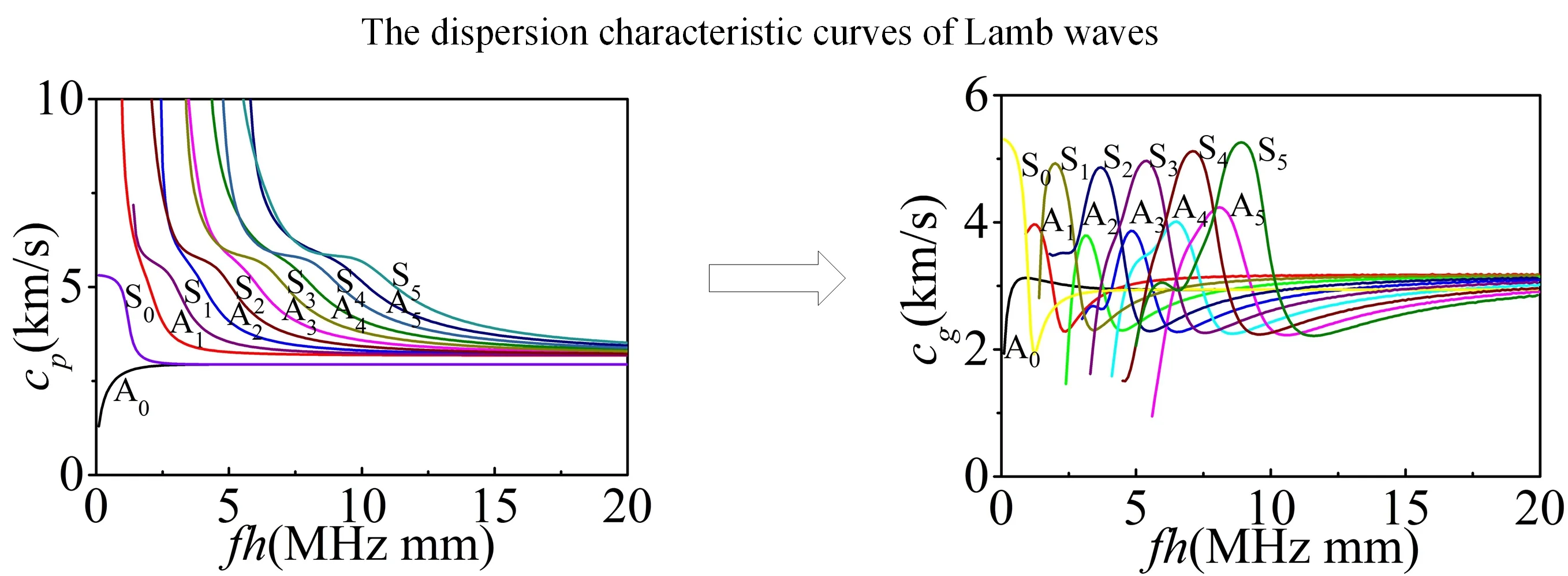
In the actual research, Lamb waves produced by the transducer are usually circular-crest Lamb waves. The circular-crest Lamb waves can be treated as straight-crest Lamb waves before a micro defect when spread over a long distance and meet the micro defects. In the experimental or numerical research, we often need to use straight-crest Lamb waves to research the propagation characteristics and interaction with micro defects. The dispersion characteristic equations and wave structure equations of straight-crest Lamb waves were solved using MatLab software through dichotomy. The velocities of longitudinal waves and transversal waves are 5800 m/s and 3100 m/s in the plate. Fig. 1 show the dispersion characteristic curves of Lamb waves in the plates.
Fig. 1The dispersion characteristic curves of Lamb waves
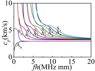
a) Phase velocities
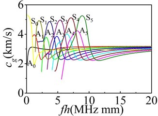
b) Group velocities
Fig. 1 shows that two or more modes of Lamb waves with different group velocities in the plate can be generated in the same frequency-thickness condition. In the region of low frequency-thickness, there are only two kinds of Lamb wave modes named the zeroth order symmetric mode (S0) and anti-symmetric mode (A0). Only the S0 and A0 mode have the cut-off frequency. The phase velocity and group velocity varies along with frequency-thickness variation. This paper focus on analyzing the interaction of the S0 and A0 mode with defects in the plates. And the 4 mm thickness finite element models of the plates are established. The reflection and transmission characteristics in 2D models and scattering properties in 3D models are studied.
3. Simulation results of Lamb waves in 2D FE model
3.1. Establish the 2D FE model
The calculated amount and calculated time can be reduced effectively in the 2D FE model. The interference of horizontal shear waves (SH waves) in the vertical direction can be also avoided. A 2000 mm long and 4 mm thickness plate is established in the ANSYS software using parametric programming commands. PLANE42 unit is selected for FM analysis. Table 1 shows the material characteristic parameters of the FE plate.
Table 1The material characteristic parameters of finite element simulation model
Parameters | Elastic modulus (E) | Poisson-ratio () | Density () |
Value | 204 MPa | 0.284 | 7860 kg/m3 |
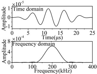
Here the sinusoidal signal with five cycles is modulated by Hanning window as excitation signal to generate mechanical vibration in the plate. The high frequency interference and energy leakage can be eliminated effectively. Excitation signal expression shows in Eq. (10):
Here is the amplitude coefficient, is cycling number, is central frequency. means the in-plane displacement and out-of plane displacement at different instants of time .
The center frequency of excitation signal is set to 200 kHz. Fig. 2 shows the waveform of the excitation signal.
Fig. 2The excitation signal modulated by Hanning window
The dual incentive method loading displacement signal is used to generate a single mode Lamb wave in the left of the FE model. A 10 mm long nodes in the bottom and surface of plate are selected to generate S0 mode Lamb wave loading synthetic in-plane displacement, and generate A0 mode Lamb wave loading synthetic out-of-plane displacement. The minimal size of the finite element model grid should be less than 1/7 of wavelength, and the minimum meshing size is set to 0.2 mm. The near field of the defects are meshed with refined grids. The finite element computation time step should be less than 0.8 /, is the minimum meshing size, is the biggest modal velocity. The time step is set to 0.2 μs in the FE model.
Fig. 3 shows the two kinds of two-dimensional plate model. The complete FE mesh of the symmetric notch is given on Fig. 3(a). The complete FE mesh of the asymmetric notch is given on Fig. 3(b).
Fig. 3The two-dimensional FE plate model with micro defects
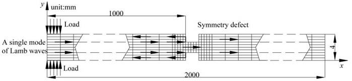
a) Symmetry defect
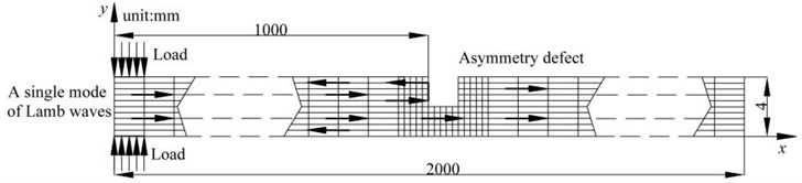
b) Asymmetry defect
3.2. The displacement nephogram of fundamental Lamb waves in 2D damaged model
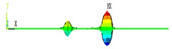
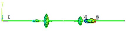
Fig. 4 and Fig. 5 show the displacement vector nephogram after Lamb waves testing the different kinds of defects in the 2D plates.
Fig. 4 and Fig. 5 show that it occurs to be obvious reflection and transmission phenomenon after Lamb waves testing the symmetry defect and asymmetry defect. When the symmetry defects are tested, there is no modal conversion phenomenon in Fig. 4. Fig. 5 shows that the reflection and transmission waves occur obvious modal conversion after S0 mode and A0 mode Lamb waves testing the asymmetry detect. In the reflection waves and transmission waves, the out-of-plate displacement is generated after S0 mode interacting with the asymmetry detects, and the in-plate displacement is generated after A0 mode interacting with the asymmetry detects.
Fig. 4The propagation of Lamb waves in the plate with symmetric defect
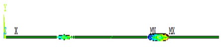
a) S0 mode in 300 µs
b) A0 mode in 400 µs
Fig. 5The propagation of Lamb waves in the 2D plate with asymmetric defect
a) S0 mode in 300 µs
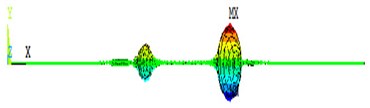
b) A0 mode in 400 µs
3.3. The wave propagation of fundamental Lamb waves in a damaged plate
In the FE model, the signal receiving nodes in the up and down surface are set to analyze the in-plate displacement signal and out-of-plate displacement signal. The waveform of symmetrical mode can be achieved by adding in-plane displacement or subtracting the out-of-plane displacement. The waveform of asymmetrical mode can be achieved by subtracting the in-plane displacement or adding the out-of-plane displacement.
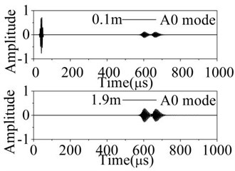
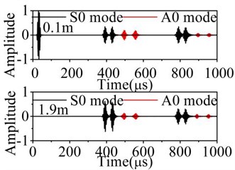
The received nodes are chosen in 0.1 m and 1.9 m to avoid the mode mixing and get the corresponding reflection waveforms. Fig. 6 and Fig. 7 show the waveform propagation of fundamental Lamb waves in the 2D damaged plates.
In the received signal, different lamb mode can be identified by calculating the group velocity. The A0 mode have obvious dispersion phenomenon and waveform expansion. In the Fig. 6, the reflection and transmission waves have no mode separation phenomenon after testing the symmetric defect. In the Fig. 7, the reflection and transmission waves have obvious mode conversion phenomenon and newly-converted modes apart from wave reflection and transmission are generated after testing the asymmetric defect. The A0 mode is generated behind S0 mode when S0 mode testing the defect. The S0 mode is generated before A0 mode after A0 mode testing the defect. In the propagation of Lamb waves, the reflection and transmission phenomenon occur again after reflection and transmission waves encountering the defect again.
Fig. 6Normalized displacements of received signal in the 2D plate with symmetric defect
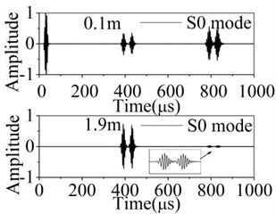
a) S0 mode
b) A0 mode
Fig. 7Normalized displacements of received signal in the 2D plate with asymmetric defect
a) S0 mode
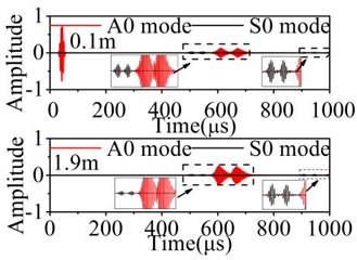
b) A0 mode
3.4. The reflection and transmission characteristics
The objective of this part is to study the reflection and transmission characteristics of Lamb waves in the 2D FM plate with a series of symmetry defects and asymmetric defects changed in the depth direction. The width of defect is set to 4 mm in the plate. The depth of symmetry defect is changed in 10 %, 20 %, 30 %, 40 % of the plate thickness. The total depth of the symmetry defect is changed in 20 %, 40 %, 60 %, 80 % of the plate thickness. The reflection and transmission coefficients are computed from the displacement of the Lamb wave packet. A comparison between the reflection and the transmission coefficients of Lamb wave when A0 mode and S0 mode are generated in the 2D plate, is represented on the Fig. 8, and the normalized amplitude is extracted to explain this sensitivity.
Fig. 8 shows that the reflection coefficient increases, and the transmission coefficient decreases with the increase of the symmetry defect depth in different Lamb mode. Compare Fig. 8(a) with Fig. 8(b), the reflection and transmission coefficient changing rate of S0 mode is faster than A0 mode. It can be noticed that the reflection mode coefficient is concentrated near to the large depth defect of the plate contrarily to the transmission mode coefficient. With the reference of the variation laws of reflection waves and transmission waves in the plate, the depth of symmetric defect can be evaluated.
The depth of asymmetry defect is changed in 10 %, 20 %, 30 %, 40 %, 50 %, 60 %, 70 %, 80 %, 90 % of the plate thickness. The width of the defect is still set to 4mm. The reflection and transmission coefficients of different modes are analyzed after Lamb waves testing the asymmetry defect. The normalized amplitude is extracted to explain this sensitivity on the Fig. 9.
Fig. 8Reflection and transmission coefficients varies with depth of symmetric defect
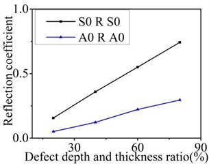
a) Reflection coefficient
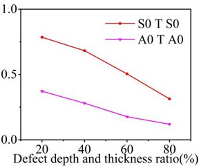
b) Transmission coefficient
Fig. 9Reflection and transmission coefficients varies with depth of asymmetric defect
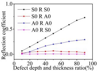
a) Reflection coefficient
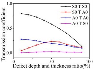
b) Transmission coefficient
When S0 mode Lamb wave testing the asymmetric defects, the reflection coefficients of S0 mode increases and the transmission coefficients of S0 mode decreases with the depth increasing of the asymmetric defect. The reflection and transmission coefficients of A0 mode increase firstly and then decrease when the depth is greater than the 50 % of the plates thickness. When A0 mode testing the asymmetric defect, the reflection and transmission phenomenon is similar to the S0 mode. The found disturbance of the normal surface component of the acoustic field due to the inclusion is considerably larger for the incident S0 mode than for the A0 mode by contrastive analysis. When S0 mode testing the defects, the reflection and transmission waves is mainly existing in the form of S0 mode. When A0 mode testing the defects, the reflection and transmission waves are mainly existing in A0 mode. With the reference of the variation laws of reflection waves and transmission waves in the plate, the depth of the asymmetric defect can be evaluated.
4. Simulation results of Lamb waves in 3D-plates FE model
In 2D plate model, the propagation characteristics of Lamb waves can be easily analyzed with less amount of calculation, but the scattering characteristics in the third dimension cannot be studied. So, 3D finite element models should be established to research the Lamb waves on propagation and interaction with the typical defects varied in third dimensional direction. In the section 2, the theory about dispersion characteristic equations and wave structure equations of the straight-crest Lamb waves and the circular-crest Lamb waves have been analyzed. The two kinds of Lamb waves have a different energy attenuation in the propagation direction. In the next step research, 3D FE model with 600 mm long, 600 mm wide and 4 mm thickness is set in ANSYS software. SOLID45 eight node structure element to mesh the 3D plate, and COMBIN14 spring-damper element to construct the non-reflective boundaries and minimize the calculation burden. The model nodes in the up and down surfaces with 20 mm long and 600 mm wide are selected in the left side of the plate to motivate a single mode straight-crest Lamb wave to research the propagation of Lamb waves in 3D model. The waveform of incentive signal is still unchanged.
4.1. The displacement nephogram and waveform of Lamb waves in 3D damaged model
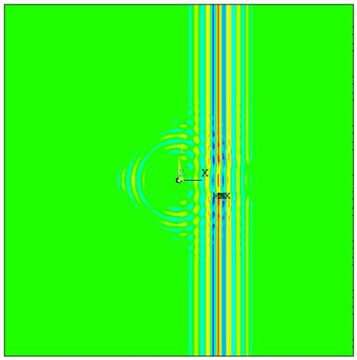
A circular hole defect and rectangular hole defect are set in the center of the plate. The ring sensor nodes are set 150 mm from the center of the defect and spaced 15°. The straight-crest Lamb waves are generated from the left side of the 3D plate. Fig. 10 shows the displacement vector nephograms after the fundamental Lamb waves testing with the through hole defects. The radius of the defect is set to 4 mm. Fig. 11 shows the received waves in different direction 150 mm from defect center.
Fig. 10The propagation of straight-crest Lamb waves in the 3D plate with through hole defects
a) S0 mode in 75 µs
b) S0 mode in 100 µs
c) A0 mode in 100 µs
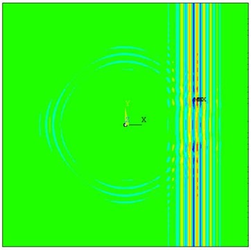
d) A0 mode in 125 µs
Fig. 11The scattering waveform of straight-crest Lamb waves in detective plate
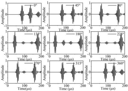
a) S0 mode
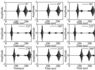
b) A0 mode
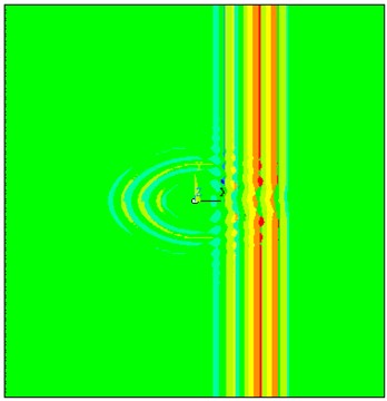
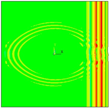
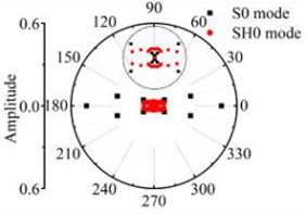
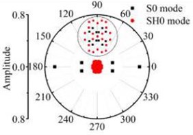
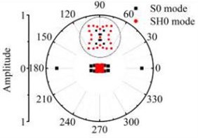
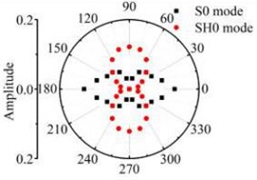
Fig. 10 shows an example simulation of the propagation of straight-crest Lamb waves in a 4 mm 3D plate with through hole defects. The straight-crest Lamb waves occur to have obvious scattering phenomenon after testing with the circular defect. S0 mode by out-of-plane displacement and A0 mode by in-plane displacement are mixed together in the 3D plate. When loading out-of-plane displacement to generate S0 mode, the scattering waves with out-of-plane displacement are mainly existing. When loading in-plane displacement to generate A0 mode, the scattering waves with in-plane displacement are mainly existing. In the Fig. 10(a), the out-of-displacement nephogram of scattering waves presents elliptical distribution after S0 mode testing the 3D defect. Newly-converted modes apart from the scattering wave are generated after testing the through holes defect. The group velocity of the scattering waves in different direction is different. According to the group velocity calculation and modal identification in the simulation results, we have found that the scattering Lamb waves have different modes containing S0 mode and SH0 mode. S0 mode transmission and reflection waves are generated in the 0° direction and 180° direction. SH0 mode scattering waves are generated in the 90° and 270° direction. In other directions, the scattering waves are superposition waves containing S0 mode and SH0 mode. SH0 shear-horizontal waves propagate slower through the damaged area than S0 Lamb waves, which is due to the difference in the group velocities. In the Fig. 10(b), the in-displacement nephogram of scattering waves presents circular distribution after A0 mode with in-plane displacement testing with through hole defect. We could then come to conclusion that the scattering wave only contains A0 mode judged by modal identification and have no modal separation phenomenon in the propagation process.
Fig. 11 shows that the S0 mode and A0 mode Lamb waves present obvious scattering phenomenon after testing the through hole defect. The scattering waves occur to reflect from boundary of the plates. The Fig. 11(a) illustrates the waveform of the out-of-plane displacement after S0 mode testing the hole defect. The Fig. 11(b) illustrates the waveform of the in-plane displacement after A0 mode Lamb wave testing the hole defect. In the propagation of straight-crest Lamb waves, the A0 mode have obvious dispersion phenomenon and waveform expansion.
The circular hole defects and rectangular hole defects are respectively set in the center of 3D plate. we can further realize to evaluate the size transformation laws of the 3D defects by comparing with the scattering waves characteristics of Lamb wave in the FE simulation.
4.2. The scattering laws of the circular hole defects changed in radial direction
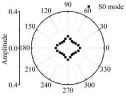
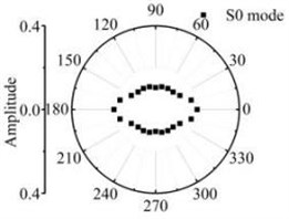
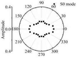
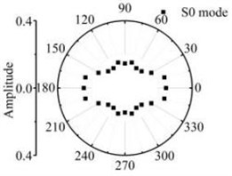
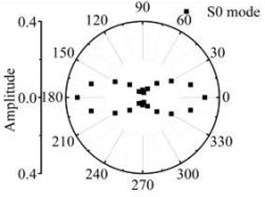
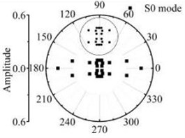
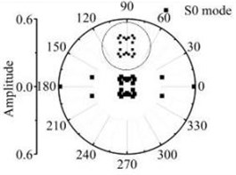
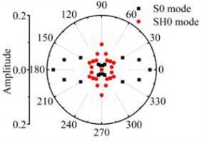
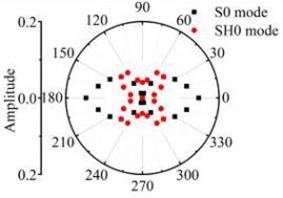
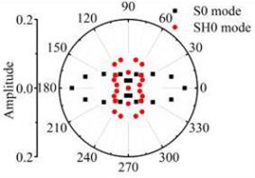
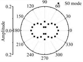
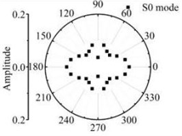
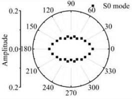
Set the radius of the circular hole defect to be 4 mm, 6 mm, 8 mm and 10 mm. The straight-crest Lamb waves are produced and the scattering laws are analyzed. The normalized amplitude of the modal decomposition scattering Lamb wave packets are extracted to study the energy distribution of the scattering waves in the 3D plate.
Fig. 12The scattering laws of S0 mode testing the radial variation circular hole defect
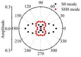
a) R4 mm
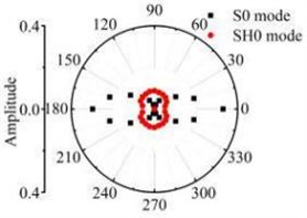
b) R6 mm
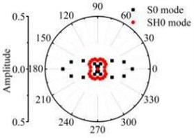
c) R8 mm
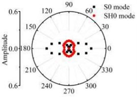
d) R10 mm
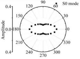
Fig. 13The scattering laws of A0 mode testing the radial variation circular hole defect
a) R4 mm
b) R6 mm
c) R8 mm
d) R10 mm
It should be noted that all scattering waves in this paper are normalised by the maximum absolute amplitude of the incident Lamb wave at the centre of the defect zone in the plate. Fig. 12 and Fig. 13 show that the scattering waves of S0 mode and A0 mode Lamb waves and SH0 mode shear horizontal waves are symmetrical about the axial and varies with similar slope. The forward ( 0°) and backward ( 180°) scattered S0 and A0 mode Lamb waves tend to have a larger amplitude for increasing in the direction. The energy of the scattering waves increases with the increase of circular defect radius. When the S0 mode testing the micro defect in the centre. The energy of S0 mode scattering waves in 0° and 180° direction is bigger than other directions. The energy of SH0 mode scattering waves in 90° and 270° direction is bigger than other direction. Contrast the energy distribution of the scattering waves after S0 mode and A0 mode Lamb wave testing the through hole defect, the S0 mode Lamb waves are more sensitive to the circular hole defect varied in the radius direction.
4.3. The scattering laws of rectangular hole defects changed in the width direction
The length of the rectangular hole defect in the middle of the plate is set to 6 mm, and the width is changed to be 12 mm, 18 mm, 24 mm and 30 mm. Fig. 14 and Fig. 15 show the scattering laws after the straight-crest Lamb waves testing the micro rectangular defect with longitudinal variation.
Fig. 14The scattering law of S0 mode testing the longitudinal variation rectangular defect

a) 6 mm×12 mm
b) 6 mm×18 mm
c) 6 mm×24 mm
d) 6 mm×30 mm
Fig. 15The scattering law of A0 mode testing the longitudinal variation rectangular defect
a) 6 mm×12 mm
b) 6 mm×18 mm
c) 6 mm×24 mm
d) 6 mm×30 mm
According to the simulations in 3D FE plate, the scattering waves of S0 mode, A0 mode Lamb waves and SH0 mode shear horizontal waves are symmetrical about the axial after Lamb waves testing the rectangular defects. Similar scattering with the through hole defect, mode conversion and directivity propagation phenomena can be noticed in the coefficient patterns. The entire energy conversion results are given in the Fig. 14 and Fig. 15. The scattering energy of S0 mode Lamb waves in the 0° and 180° direction is larger than other directions. The scattering energy increases significantly with the defect length increase. The energy of SH0 mode scattering wave increases with the defects size increase. The SH0 mode energy in rectangular corner direction is greater than that in other direction but less than S0 mode. When the width of the rectangle hole defect is 30 mm or longer than 30 mm, nearly all scattering waves are in the 0° and 180° direction. Fig. 15 shows that the A0 mode energy in the 0° and 180° direction is bigger than other directions. The scattering energy increases with the increase of the size in the width direction. The increase rate in close to 0° and 180° direction is greater than the other direction. Due to the influence of the four corners of the rectangle defect, the scattering energy on the four directions highlighted. Contrast the energy distribution of the scattering waves after S0 mode and A0 mode Lamb wave testing the rectangular defect, simulation results indicate that the amplitude of scattered S0 and A0 Lamb waves is sensitive to orientation up to 0° and 180° respectively for excitation at rectangular defect.
4.4. The scattering laws of the rectangular hole defects changed in length direction
The width of rectangular hole defects is set to 6 mm. The length is changed to be 12 mm and 18 mm and 24 mm and 30 mm. Fig. 16 and Fig. 17 show the scattering laws after the straight-crest Lamb waves interacting with the defects with transverse variation.
Fig. 16The scattering laws of S0 mode testing the transverse variation rectangular hole defects
a) 12 mm×6 mm
b) 18 mm×6 mm
c) 24 mm×6 mm
d) 30 mm×6 mm
Fig. 16 and Fig. 17 show that after Lamb waves testing the rectangular hole defect, the scattering energy of S0 A0 mode Lamb waves and SH0 mode shear horizontal waves do not increases significantly with the increase of rectangular hole defect in the width direction. The energy of SH0 mode scattering waves is bigger in the directions of four corners in the defect obviously. The energy of A0 mode scattering waves has no obvious law with the transverse variation. It can be deduced from the above study, that the existence of S0 mode along with A0 mode is a definite indication of scatter waves in the path of its propagation and has an orientation behaviour after testing the rectangular hole defect. Comparative analysis about the scattering phenomenon after the Lamb waves testing the rectangle defect changed in the width and length direction shows that the Lamb waves are more sensitive to rectangular hole defects varied in the width direction. It is not sensitive to the rectangular hole defects changed in the length direction.
Fig. 17The scattering laws of A0 mode testing the transverse variation rectangular hole defects
a) 12 mm×6 mm
b) 18 mm×6 mm

c) 24 mm×6 mm
d) 30 mm×6 mm
5. Conclusions
In this paper, comparative analysis firstly in theory about the straight-crest Lamb waves and the circular-crest Lamb waves indicates that two kinds of Lamb waves in plates has the same dispersion characteristic and wave structure characteristic, but different in the energy attenuation. The circular-crest Lamb waves can be treated as straight-crest Lamb waves before a micro defect when spread over a long distance and meet the micro defects. In the next step, a numerical study of the fundamental Lamb waves interaction with the symmetrical, asymmetrical notches, circular hole defects and rectangular hole defects was conducted.
It was found in the 2D FE plate that the reflection and transmission waves generated obvious mode conversion phenomenon after testing with the asymmetry notches. But after testing with the symmetry notches, the reflection and transmission waves have no mode conversion phenomenon. The notch analysis presented in Section 3.4 shows the effect of notch depth on the transmitted and reflected modes along with the mode conversion of Lamb wave. The energy of reflection waves increases with increases of the depth and the energy of transmission waves decrease with the increases of the depth. The energy of mode converted Lamb mode in the reflection and transmission waves first increases with the increase in asymmetrical notch width, then decreases when the depth is greater than 50 % of the plate thickness.
In the 3D numerical simulations, the scattering waves occur to generate S0 mode Lamb waves and SH0 mode shear horizontal waves after S0 mode testing the through hole defects. The scattering waves have no mode conversion when A0 mode Lamb waves testing with the through hole defects. The energy of scattering waves increases with the increase of the defect size. The energy of S0 mode scattering waves in 0° and 180° direction is larger than other directions. The energy of A0 mode scattering waves in the 0°, 90°, 180°, 270° direction is significantly greater than the other direction after interacting with circular hole detects. Energy bound state of the scattering waves does exist in the direction of the corner when testing the rectangular hole defects. Comparative analysis about the scattering phenomenon after Lamb waves testing the rectangle defects varied in the width and length direction shows that the Lamb waves are more sensitive to rectangular hole defects changed in the width direction in testing the plates. The numerical results have also shown that the study of the reflection and transmission phenomenon of the Lamb waves across a micro defect of plates is very difficult and requires a careful analysis in the single process. In the future research, we can do more work about the experimental measurements and design digital signal processing method as the artificial intelligence algorithm to identify and locate defects accurately.
References
-
Santhanam S., Demirli R. Reflection and transmission of fundamental Lamb wave modes obliquely incident on a crack in a plate. Ultrasonics Symposium (IUS), 2012, p. 2690-2693.
-
Mori N., Biwa S. Interaction of Lamb waves with an imperfect joint of plates: reflection, transmission and resonance. Physics Procedia, Vol. 70, 2015, p. 480-483.
-
Purekar A., Pines D. Damage detection in thin composite laminates using piezoelectric phased sensor arrays and guided lamb wave interrogation. Journal of Intelligent Material Systems and Structures, Vol. 21, Issue 10, 2010, p. 995-1010.
-
Michaels T. E., Michaels J. E., Ruzzene M. Frequency-wavenumber domain analysis of guided wavefields. Ultrasonics, Vol. 51, Issue 4, 2011, p. 452-466.
-
Rose J. Ultrasonic Waves in Solid Media. Cambridge University Press, New York, 1999.
-
Su Z., Ye L. Identification of Damage Using Lamb Waves: from Fundamentals to Applications. Springer, Science & Business Media, 2009.
-
Imano K., Endo T. Experimental study on the mode conversion of lamb wave using a metal plate having a notch type defect. International Journal of the Society of Materials Engineering for Resources, Vol. 19, Issue 12, 2013, p. 20-23.
-
Xu K., Ta D., Su Z., et al. Transmission analysis of ultrasonic Lamb mode conversion in a plate with partial-thickness notch. Ultrasonics, Vol. 54, Issue 1, 2014, p. 395-401.
-
Lamb H. On waves in an elastic plate. Proceedings of the Royal Society of London A: Mathematical, Physical and Engineering Sciences, 1917, p. 114-128.
-
Viktorov I. A. Rayleigh and Lamb Waves: Physical Theory and Applications. Plenum Press, 1970.
-
Worlton D. Ultrasonic testing with Lamb waves. General Electric C, Hanford Atomic Products Operation, Richland, Wash., 1956.
-
Alleyne D. N., Cawley P. A 2-dimensional Fourier transform method for the quantitative measurement of Lamb modes. Ultrasonics Symposium, 1990, p. 1143-1146.
-
Wilcox P. D. A rapid signal processing technique to remove the effect of dispersion from guided wave signals. IEEE Transactions on Ultrasonics, Ferroelectrics, and Frequency Control, Vol. 50, Issue 4, 2003, p. 419-427.
-
Deng W., Zhang S., Zhao H., et al. A novel fault diagnosis method based on integrating empirical wavelet transform and fuzzy entropy for motor bearing. IEEE Access, Vol. 6, Issue 1, 2018, p. 35042-35056.
-
Zhao H., Sun M., Deng W., et al. A new feature extraction method based on EEMD and multi-scale fuzzy entropy for motor bearing. Entropy, Vol. 19, Issue 1, 2016, p. 14.
-
Deng W., Yao R., Zhao H., et al. A novel intelligent diagnosis method using optimal LS-SVM with improved PSO algorithm. Soft Computing, 2017, https://doi.org/10.1007/s00500-017-2940-9.
-
Deng W., Zhao H., Yang X., et al. Study on an improved adaptive PSO algorithm for solving multi-objective gate assignment. Applied Soft Computing, Vol. 59, 2017, p. 288-302.
-
Deng W., Zhao H., Liu J., et al. An improved CACO algorithm based on adaptive method and multi-variant strategies. Soft Computing, Vol. 19, Issue 3, 2015, p. 701-713.
-
Deng W., Chen R., Gao J., et al. A novel parallel hybrid intelligence optimization algorithm for a function approximation problem. Computers and Mathematics with Applications, Vol. 63, Issue 1, 2012, p. 325-336.
-
Elsayed S. M., Sarker R. A., Essam D. L. An improved self-adaptive differential evolution algorithm for optimization problems. IEEE Transactions on Industrial Informatics, Vol. 9, Issue 1, 2013, p. 89-99.
-
Zhao H., Li D., Deng W., et al. Research on vibration suppression method of alternating current motor based on fractional order control strategy. Proceedings of the Institution of Mechanical Engineers, Part E: Journal of Process Mechanical Engineering, Vol. 231, Issue 4, 2017, p. 786-799.
-
Deng W., Chen R., He B., et al. A novel two-stage hybrid swarm intelligence optimization algorithm and application. Soft Computing, Vol. 16, Issue 10, 2012, p. 1707-1722.
-
Deng W., Zhao H., Zou L., et al. A novel collaborative optimization algorithm in solving complex optimization problems. Soft Computing, Vol. 21, Issue 15, 2017, p. 4387-4398.
-
Ramadas C., Hood A., Khan I., et al. Transmission and reflection of the fundamental Lamb modes in a metallic plate with a semi-infinite horizontal crack. Ultrasonics, Vol. 53, Issue 3, 2013, p. 773-781.
-
Mori N., Biwa S., Hayashi T. Reflection and transmission of Lamb waves at an imperfect joint of plates. Journal of Applied Physics, Vol. 113, Issue 7, 2013, p. 74901.
-
Cho Y., Rose J. L. A boundary element solution for a mode conversion study on the edge reflection of Lamb waves. The Journal of the Acoustical Society of America, Vol. 99, Issue 4, 1996, p. 2097-2109.
-
Moulin E., Assaad J., Delebarre C., et al. Modeling of Lamb waves generated by integrated transducers in composite plates using a coupled finite element-normal modes expansion method. The Journal of the Acoustical Society of America, Vol. 107, Issue 1, 2000, p. 87-94.
-
Balasubramanyam R., Quinney D., Challis R., et al. A finite-difference simulation of ultrasonic Lamb waves in metal sheets with experimental verification. Journal of Physics D: Applied Physics, Vol. 29, 1, p. 1996-147.
-
Ahmad Z., Gabbert U. Simulation of Lamb wave reflections at plate edges using the semi-analytical finite element method. Ultrasonics, Vol. 52, Issue 7, 2012, p. 815-820.
-
Benz R., Niethammer M., Hurlebaus S., et al. Localization of notches with Lamb waves. The Journal of the Acoustical Society of America, Vol. 114, Issue 2, 2003, p. 677-685.
-
Castaings M., Singh D., Viot P. Sizing of impact damages in composite materials using ultrasonic guided waves. NDT & E International, Vol. 46, 2012, p. 22-31.
-
Feng F., Shen J., Lin S. Scattering matrices of Lamb waves at irregular surface and void defects. Ultrasonics, Vol. 52, Issue 6, 2012, p. 760-766.
-
Ng C., Veidt M., Rose L., et al. Analytical and finite element prediction of Lamb wave scattering at delaminations in quasi-isotropic composite laminates. Journal of Sound and Vibration, Vol. 331, Issue 22, 2012, p. 4870-4883.
Cited by
About this article

