Abstract
Ultrasonic Lamb wave is a promising tool for structural health monitoring and nondestructive evaluation of plate-like structures. Using an array with several piezoelectric discs for damage imaging (i.e. visual detection and localization) is of interest. Commonly used delay-and-sum method is limited for overlapped signals when several damages are closely distributed in the structure. To overcome this limitation, modal-based sparse reconstruction imaging method is applied for adjacent damages in this study. Firstly, Lamb wave dispersion curve is obtained by solving the Rayleigh-Lamb equations. Subsequently, propagation modal of the damage-reflected signal is constructed based on the solved dispersion curve. Finally, the modal is used for damage imaging via sparse reconstruction and basis pursuit de-noising. Experimental data measured in an aluminum plate is considered, and the result demonstrates that the sparse reconstruction imaging method is effective to detect and localize closely distributed damages in the presence of signal overlapping.
1. Introduction
Lamb wave is considered as a promising tool for damage detection in plate and pipe-like structures, because it can propagate over a long distance with low attenuation and sensitive to small changes in structural property [1]. To visualize the damage intuitively in a two-dimensional image, Lamb wave imaging technique by using several piezoelectric discs is developed.
Delay-and-sum (DAS), also known as elliptical imaging, is a representative and most commonly used Lamb wave imaging method. Based on the assumption that reflection occurs when Lamb wave encounters damage, the DAS image is generated by shifting and adding the reflected waves according to an appropriate time shifting rule [2]. In practical application, DAS is generally applied to residual signals, i.e. subtraction of reference signals from damage signals. This method is easy to understand and computationally undemanding. However, DAS imaging is limited if there are multiple sites of damage, especially when multiple damages are closely distributed, and the corresponding reflected signals overlap with each other.
Besides DAS, commonly used Lamb wave imaging techniques include tomography [3], correlation imaging [4] and multipath imaging [5] et al. In practice, all of these techniques have limited performance for overlapped signals.
Different from these techniques, a sparse reconstruction imaging method is proposed by researchers with the assumption that the inspection area is mostly damage-free. Previous work has applied this method for Lamb wave single-mode, multi-mode and mode-converted propagation environments, and also for single- and multi-path environments [6-8]. However, none of the aforementioned work considered the application of sparse reconstruction imaging for multiple closely distributed damages. In this paper, we present an implementation scheme of using this imaging method to detect and localize several closely adjacent damages. The implementation scheme is as follows. Firstly, Lamb wave dispersion curve is obtained by solving the Rayleigh-Lamb equations. Subsequently, the solved dispersion curve is utilized to yield propagation modal of the wave packet reflected from the damage. Finally, the modal is applied for damage imaging via sparse reconstruction and basis pursuit de-noising.
The rest of this paper is organized as follows. Implementation scheme of Lamb wave sparse reconstruction imaging method is reviewed briefly in section 2. Experimental investigation of this method for detecting and localizing closely distributed damages is given in section 3. Conclusions are given in section 4.
2. Methodology
2.1. Lamb wave dispersion
Lamb waves could be regarded as elastic vibration propagating in a solid plate (or layer) with free boundaries. The vibration occurs both in the direction of wave propagation and perpendicularly to the plane of the plate. Considering an isotropic plate of thickness 2, a finite number of symmetrical and anti-symmetrical Lamb waves exist at an angular frequency . The following Rayleigh-Lamb equations are satisfied:
where is the wave-number. The coefficients and are given by:
where and are the velocities of longitudinal and transverse/shear mode, respectively. The roots of Eq. (1) for (, ) allow to obtain the Lamb wave dispersion curves for the isotropic plate, which can be expressed as the wave-number, , versus frequency or frequency-thickness product, i.e. .
2.2. Construction of propagation modal based on dispersion
Assume that two Lamb wave transducers are positioned on a plate (or layer), which act as the transmitter and receiver, respectively. The locations of transmitter and receiver are and , respectively. Assume a defect is present at location . When the transmitter is excited with a signal , the propagating Lamb wave encounters the defect and the wave experiences reflection, the reflected wave packet captured by the receiver can be defined by out-of-plane surface displacement as:
where is the Fourier transform of , is the dispersion curve of the propagation mode, is the propagation distance of the reflected wave. The number of signal samples is .
A transducer array with transmitter-receiver pairs is used, and the purpose is to locate a limited number of defects in the plate. To find these defects, propagation modal containing the reflected wave packets for all the transmitter-receiver pairs and all potential defects is needed. Here, the inspection area of the plate is divided into a sufficiently fine grid consisting of pixels where each pixel represents a potential defect.
The reflected wave packets of these potential scatterers will form the columns of the matrix A. The × matrix is defined as:
Here, is the reflected wave packets corresponding to th potential defect and all the transmitter-receiver pairs:
If a defect locates at potential location , without considering signal noise, the corresponding th column of matrix will be consistent with the actual measured reflected signal. On this basis, the modal could be utilized for defect localization and imaging.
2.3. Modal-based defect imaging via sparse reconstruction
To detect and localize damage in the plate with transmitter-receiver pairs, Lamb wave excitation/acquisition procedures are needed in both reference (typically damage-free) and damage states. Then, residual signals are obtained by differencing the signal from the damage plate and that from the damage-free plate. These residual signals are organized as a column vector:
Sparse reconstruction is applied to build the relationship between measured signal and propagation modal , using the form . Here, vector represents the pixel values of the pixel locations, with indicating the th pixel location . If a defect exists at , then will be non-zero. Vector e is white noise. The form is effective because measured residual signals, in theory, equals to the reflected wave packets plus noise.
The problem for solving is underdetermined, and there are infinitely many solutions. Sparse reconstruction is a method for solving underdetermined problem by assuming that most components of the solution are zero-valued, i.e. most elements of vector are zero-valued. This assumption is reasonable because most inspection area of the plate is damage-free, i.e. the damage is sparse.
The basis pursuit de-noising method is used in this paper to recover the sparse vector , i.e. we can solve the following optimization problem:
where is a coefficient to balance sparsity and accuracy. After solving , the vector is reshaped into an × matrix that represents the final image.
3. Case study
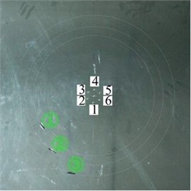
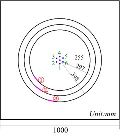
A damage imaging experiment, where several damages are closely distributed in an aluminum plate, was used to to validate the effectiveness of the proposed method for high-resolution Lamb wave inspection. The dimensions of the aluminum plate are 1000 mm×1000 mm×2 mm. In the form of through-thickness rectangular slots, 3 artificial defects were introduced in the plate. To detect the defects, 7 PZTs (piezoelectric ceramic discs) with a diameter of 8 mm and 0.5 mm in thickness were networked as a clock-like transducer array where the circle has the dimensions of 60 mm. In this PZT array, the one located at the center serves as the transmitter, while others serve as receivers. A photograph and the schematic diagram of the specimen with defects and the transducer array are shown in Fig. 1. Three artificial defects are 255 mm, 297 mm and 348 mm away from the transmitter, respectively.
The setups of this experiment include an Agilent 33220A function/arbitrary waveform generator, a Piezo Systems EPA-104 voltage amplifier, a AVANT NI-2000 conditioning amplifiers and a NI PXIe-1082 data acquisition. 3-cycle Hann windowed tone burst centered at 80 kHz is used as the excitation signal, for which A0 mode is dominant for this plate thickness. The residual responses captured by the receiver array are shown in Fig. 2.
Fig. 1Aluminum plate (2-mm thick) with three damage slots and the clock-like sensor array: a) photograph; b) schematic diagram
a)
b)
Fig. 2Residual responses captured by the sensor array
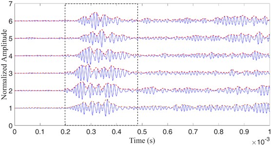
From Fig. 2, it can be seen that the three defect-reflected wave packets enclosed by the dashed line rectangle overlap with each other. The overlap comes from the fact that the three defects are closely distributed in the plate. In addition, the overlap degree is further increased by the dispersion characteristic of Lamb wave. The overlap phenomenon changes the location of the peak of each wave packet, resulting in an erratic fluctuation in the envelope curve. As a result, traditional imaging methods (e.g. delay and sum) will be invalid.
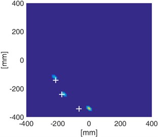
To improve the inspection resolution, the modal-based sparse reconstruction method is applied for damage imaging. The imaging result is shown in Fig. 3. The central locations of actual defects are marked by “+”. As can be seen, the three defects are clearly detected and localized with acceptable errors, demonstrating that the sparse reconstruction method is effective for imaging of closely distributed damages.
Fig. 3Imaging result obtained from array residual signals
4. Conclusion
The application of Lamb wave sparse reconstruction imaging method for several closely distributed damages is presented in this study. Compared to traditional Lamb wave imaging techniques (i.e. DAS, tomography, correlation imaging and multipath imaging), the main advantage of the sparse reconstruction imaging is its adaptability to overlapped signals. Single-mode (A0 mode) and single-path (damage-reflected path) propagation environments are considered in this study. The future work should use multi-mode and multi-path propagation modal to see whether the current imaging performance is still available under such complicated signal environment.
References
-
Tua P. S., Quek S. T., Wang Q. Detection of cracks in plates using piezo-actuated Lamb waves. Smart Material and Structures, Vol. 13, Issue 4, 2004, p. 643-60.
-
Giurgiutiu V., Bao J. J. Embedded-ultrasonics structural radar for in situ structural health monitoring of thin-wall structures. Structure Health Monitoring, Vol. 3, Issue 2, 2004, p. 121-140.
-
Belanger P., Cawley P. Feasibility of low frequency straight-ray guided wave tomography. NDT&E international, Vol. 42, Issue 2, 2009, p. 113-119.
-
Quaegebeur N., Masson P. Correlation-based imaging technique using ultrasonic transmit-receive array for non-destructive evaluation. Ultrasonics, Vol. 58, Issue 2, 2012, p. 1056-1064.
-
Hall J. S., Michaels J. E. Multipath ultrasonic guided wave imaging in complex structures. Structure Health Monitoring, Vol. 14, Issue 4, 2015, p. 345-358.
-
Levine R. M., Michaels R. M. Model-based imaging of damage with Lamb waves via sparse reconstruction. Journal of the Acoustical Society of America, Vol. 133, Issue 3, 2013, p. 1525-1534.
-
Golato A., Santhanam S., Ahmad, et al. F. Multimodal sparse reconstruction in Lamb wave-based structural health monitoring. Proceedings of SPIE, 2014, p. 9109.
-
Leigsnering M., Ahmad F., Amin M., et al. Multipath exploitation in through-the-wall radar imaging using sparse reconstruction. IEEE Transactions on Aerospace and Electronic Systems, Vol. 50, Issue 2, 2014, p. 920-939.
About this article

The authors declare that there is no any potential conflict of interests in the research. This study was supported by the Fundamental Research Funds for the Central Universities (Grant No. YWF-16-BJ-J-18) and the National Natural Science Foundation of China (Grant Nos. 51575021 and 51605014), as well as the Technology Foundation Program of National Defense (Grant No. Z132013B002).
