Abstract
In order to monitor the crack propagation of the structure in the working state for a long time, an operation modal analysis method based on pseudo-successive data is proposed. The vibration response signals of the cantilever beam under white noise excitation are collected and the modal parameters are extracted by the time-frequency operation modal analysis method based on the complex Morlet wavelet. In comparison with the experimental modal analysis results of hammering method, it is revealed that the error of the time-frequency operation modal analysis method is less than 10 %. By setting cracks of different lengths on the cantilever beam, the vibration response signals are extracted, and the modal parameters are extracted by the operation modal analysis method separately. By comparing those modal parameters above, it is found that the natural frequencies of the second, the fourth and the sixth orders decrease with the increase of the crack depth, and the changes of natural frequencies show the monotonicity. So, it can be used as an index for quantitative identification of crack damage. The pseudo continuous data monitoring signals of crack propagation can be constructed by means of “first discrete, then continuous”. The modal parameters changes of the whole crack propagation can be observed in one time plane by means of the operation modal analysis method. Therefore, the effective monitoring and diagnosis of the structure can be completed in case of excessive data of long-time vibration monitoring signals.
1. Introduction
Crack is one kind of structural failure which exists widely on mechanical equipment, and it has the feature of easy to extend, hard to find, and strong destruction. Figuratively, it’s called “cancer” to the mechanical equipment, and “invisible killer” to equipment structure. In industries such as equipment, aerospace, energy, power and defense, accidents caused by crack or its expansion often result in great losses [1]. Therefore, it’s significantly important to identify cracks for the safety operation of equipment. However, the study of vibration characteristics and monitoring methods of structures during crack propagation now faces many difficulties, because the vibration monitoring signals is too long because of the long-time history of crack growth.
In the field of crack fault detection, many scholars pay close attention to the method of quantitative diagnostic based on structural modal parameter. The structural crack damage always leads to the change of local stiffness, which result in the change of modal parameters of the structure (natural frequency, damping ratio and mode of vibration). In paper [2], the change of the natural frequency pioneered the application on the identification of structural damage. The relationship between the ratio of the two order natural frequencies and damage location of structure is has been discovered in a structure with damage of a single crack in paper [3]. In paper [4], the wavelet finite element method is applied to the modal analysis of singular problems of cracked beams, and the matching pursuit problem in crack identification is transformed into a multidimensional optimization problem. As the key part of the diagnosis method, the identification of modal parameters traditionally relies on the experimental modal analysis method. The experimental modal analysis method can solve the dynamic parameters by means of the input and output signals of the structural system, which has obtained a great deal of research results. However, the experimental modal analysis method in modal parameter extraction structures are often limited to the size or engineering conditions of the structure, therefore it has not been well promoted in practical engineering.
On the issue of overcoming this problem, operational modal analysis shows a good prospect in crack diagnosis. Operational modal analysis can realize modal parameter identification just through the vibration condition of signal. In this way, it gets rid of the limitations from the experimental modal analysis in terms of the size of the test structure and the sensitive working conditions. Meanwhile, it’s not depending on excitation signals extends the applicability of the method in engineering. Essentially, operational modal analysis bridges the gap between crack diagnosis based on modal parameters and vibration signal analysis. Operational modal analysis is a processing method based on structural vibration signals, but it extracts the modal parameters of the structure. It can be used as a parameter with definite physical meaning, and can also be used to diagnose crack damage.
More importantly, monitoring of long duration propagation of structural cracks has great significance on the study of the characteristics of structural vibration, the evolution of modal parameters and the establishment of quantitative standard library for crack propagation. In order to cope with the excessive amount of running state data during the whole crack growth process, a pseudo continuous data driven method for monitoring crack condition is proposed in this paper. The use of “first discrete, then continuous” approach constructs the monitoring signal of pseudo-successive data for crack propagation. Then the operational modal analysis is used to quantitatively identify the depth of the crack damage. This study provides an effective means for long time monitoring of crack propagation.
2. Theoretical background
The Operational modal analysis is made up of three methods which is the time domain, the frequency domain and the time-frequency domain. The method by the time-frequency operation modal analysis method based on the complex Morlet wavelet really achieved very good results on parameter identification of the time-varying structure [5].
Consider a single degree-of-freedom (SDOF) linear system with its governing equation expressed as [6, 7]:
where , and are respectively the mass, viscous damping and stiffness matrices.
For undammed system or when the damping is relatively small, the free vibration solution of Eq. (1) can be simplified as:
in which, , , , and are determined by system initial conditions.
Thus, is an amplitude modulated signal and its analytical form can be obtained via Hilbert transform:
The amplitude of is suggested to vary much slower than the frequency does which satisfies most dynamic responses in practice. Thus, a complex signal of can be introduced as:
The wavelet transform of can be calculated by:
Eq. (6) is then expanded using Taylor series at :
With the higher-order components ignored in Eq. (7), one gets:
Substitute Morlet wavelet function and Eq. (2) into (7), one obtains:
Eq. (8) approaches its maximum when :
Thus at , it is found that the frequency and damping ratio of the SDOF system can be estimated from the argument slope of the wavelet transformed signals and skeleton diagram of logged wavelet coefficients, respectively. Noting that only discrete signals are recorded in practice, the variable is thus and for discrete wavelet transform of the input signal where and are respectively the sampling frequencies of the wavelet functions and dynamic responses.
It reveals that multi-frequency signals can be effectively decoupled into single frequency components via continues wavelet transform instead of using band-pass filters. Thus, wavelet transform is more suitable for analyzing systems parameters multiple degrees-of-freedom systems. The model frequency can be evaluated wavelet ridge, and the damping ratio is obtained from the real part of the wavelet skeletons.
3. Extraction of modal parameters of the operation modal analysis
A test platform was built to verify the validity of the operation mode analysis in extracting modal parameters, as shown in Fig. 1. As an efficient and accurate modal test method, the accuracy of the results of hammering method is widely recognized. Firstly, the experimental modal analysis results of cantilever beam by hammering method are used as the comparison result. Then the operation modal analysis of the cantilever beam is carried out, and the results will be compared with the comparison result to verify the veracity of results of the time-frequency operation modal analysis method.
Fig. 1The experimental system diagram
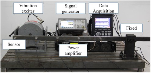
The cantilever beam of 1000 mm in length and a rectangular cross-section of 30 mm×60 mm is made by steel Q235.White Gaussian noises whose frequency range varies from 0 Hz to 700 Hz were separately applied to the cantilever beam. The vibration response signals were collected by five acceleration sensors. Responses sampled at a frequency of 1.28 KHz for 20 s are presented in Fig. 2. The complex Morlet wavelet transform is applied to the response signal collected from sensor No. 3, and the wavelet ridge in the time-frequency plane identification is used to identify the modal of the structure. With the wavelet time-frequency plan shown in Fig. 3.
The mode natural frequency of wavelet ridge could be extracted according to Eq. (6). In comparison with the experimental modal analysis results of hammering method, it is revealed that the error of the time-frequency operation modal analysis method is less than 10 %. The comparison results are shown in Table 1. It is proved that the modal of the structure identified by the time-frequency operation mode analysis method based on the continuous wavelet transform is veracious, when the cantilever beam is excited under white noise.
Fig. 2Vibration response signal
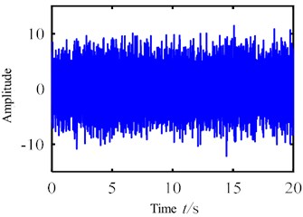
Fig. 3Wavelet transform time-frequency map
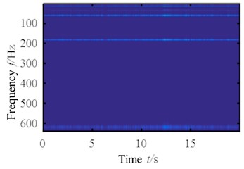
Table 1The result of OMA and the error
The order | 1 | 2 | 3 | 4 | 5 | 6 |
The result of hammering method (Hz) | 12.473 | 65.992 | 186.193 | 372.047 | 441.392 | 616.728 |
The result of OMA (Hz) | 12.5 | 65 | 187.5 | 385 | 413 | 625 |
The error (%) | 0.26 | –1.50 | 0.70 | 3.48 | –6.43 | 1.34 |
4. Crack depth quantitative diagnosis with operation modal analysis
The changes of structural modal parameters can be regard as the sign of early occurrence and depth changes of structural crack damage. Similarly, it can quantitatively diagnose the crack depth of the structure with the identification of the natural frequency. There are cracks with different depths setting on the cantilever beam. The vibration response signals of the cantilever beam with crack under white noise excitation are collected and the modal parameters are extracted by the operation modal analysis. Then, the crack depth could be diagnosed with the results of the operation modal analysis.
The crack is set by wire cutting with high cutting precision to ensure that the gaps between the cracks are small enough to be similar to the actual condition. The conditions of excitation of the experiment, the fixed methods of the cantilever beam and the sampling settings are the same as the experiments introduced in section 2. The vibration response signals of the cantilever beams with absolute depths of 2 mm, 4 mm, 6 mm, 8 mm, 10 mm, 12 mm, 14 mm, 16 mm, 18 mm and 20 mm under white noise excitation are separately collected. The wavelet time-frequency maps of the results of operation modal analysis with these signals were shown in Fig. 4.
Fig. 4Wavelet transform Tine-frequency map with different crack depths
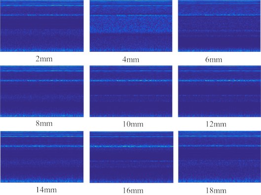
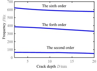
The natural frequencies of cantilever beams with cracks of different depth could be identified by the modal natural frequency of the structure with the extraction of the wavelet ridges. In comparison with identification results, the influence of crack depth on the natural frequency of each order mode is summarized. The results of experiments show that the natural frequencies of the fourth and sixth order are greatly affected by the crack depth. The influence of crack depth on the natural frequency of these three orders is shown Fig. 5.
Fig. 5A schematic diagram of a vibration separator
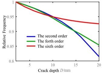
The relative natural frequency refers to the ratio of the natural frequency of the cracked beam to the natural frequency of the non-cracked beam which can obviously find the change tendency of natural frequency. As the diagram shows above that with the expansion of crack depth, the natural frequency of the structure decreases and the trend of decreasing is monotonicity. After getting the relationship between the crack depth and the natural frequency, the crack depth under structural operation condition can be diagnose by the extraction of natural frequencies with operation modal analysis.
5. Damage identification based on Pseudo-successive data
In the actual working conditions, the crack propagation is a continuous process. The monitoring of crack propagation can not only be used to evaluate the health status of the whole structure, but also of great value to study the law of crack propagation and life prediction. However, the crack propagation is a long time process. Gasch, a famous crack researcher, has pointed out that rotor crack faults are difficult to diagnose by short time steady-state operation data, the longtime monitoring of the rotor’s dynamic response is a reliable method for on-line diagnosis of rotor crack faults [8]. However, it is difficult to analyze the crack propagation from the whole time dimension because of the large amount of data processing in the long term monitoring of the structure. In order to monitor the whole process of crack propagation, Sampling is performed to extract discrete phasic signal through vibration signals throughout the crack propagation. A continuous signal is constructed by “first discrete, then continuous”, this method of constructing signals is referred to in this paper pseudo-successive data method. In order to simulate the actual crack propagation situation, the vibration signals are simulated in the form of sampling in the existing discrete crack depth. The vibration signal data of the cantilever beam is collected where the crack depth is from 2 mm to 20 mm, the sampling frequency is 1280 Hz, and the length of each signal is 2 s and the simulation of crack extension vibration signal as shown in Fig. 6.
Fig. 6Vibration signal built by pseudo-successive method
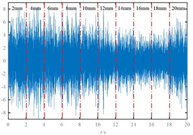
Fig. 7Wavelet transform Tine-frequency map of the signal built by pseudo-successive method
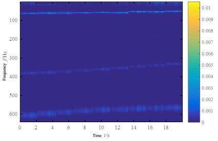
The above pseudo continuous signal can represent a basic process of crack propagation, the vibration signals above are subjected to operational modal analysis transformation. From the Section 3, it is known that the second, fourth, sixth order mode of the experiment is sensitive to the depth of the crack and can be used as an index to evaluate the crack propagation, Therefore, interference from other components is ruled out. The Butterworth filter is used to filter the frequency bands corresponding to the natural frequencies of the first, third, fifth order modes, using singular value decomposition to highlight the main components of the signal, the time-frequency map is obtained, as shown in Fig. 7.
It can be seen from Fig. 7, The frequency of operational modal analysis modal frequency identification of structures with crack growth and decline, and the frequency of operational modal analysis can be observed in the whole process of crack propagation, this method can be used as a monitoring method to study the mechanism and law of structural crack propagation in the running state, and also can be used as an index basis for life prediction of cracked components.
The modal analysis of the vibration response of a cracked beam is carried out by pseudo-successive data drive, In the case of large amount of long time vibration monitoring signal data, it can be processed from a generalized “sampling” angle to complete the effective monitoring and diagnosis of the structure.
6. Conclusions
In this paper, based on the modal analysis in time-frequency domain, a method of long time monitoring of crack propagation is proposed through the construction of pseudo-successive data. In this method, the modal parameters are identified by the operational modal analysis of the structure with cracks. Quantitative diagnosis of cracks depth has been completed and the whole process of crack propagation is observed in the wavelet time-frequency domain. This method is universal for monitoring crack growth and can be widely applied to monitoring crack propagation in other key equipment structure.
References
-
Singh S. K., Tiwari R. Detection and localization of multiple cracks in a shaft system: an experimental investigation. Measurement, Vol. 53, 2014, p. 182-193.
-
Lifshitz J. M., Rotem A. Determination of reinforcement unbonding of composites by a vibration technique. Journal of Composite Materials, Vol. 3, Issue 3, 1969, p. 412-423.
-
Cawley P., Adams R. D. The location of defects in structures from measurements of natural frequencies. Journal of Strain Analysis for Engineering Design, Vol. 14, Issue 2, 1979, p. 49-57.
-
Li B., Chen X. F., Ma J. X., et al. Detection of crack location and size in structures using wavelet finite element methods. Journal of Sound and Vibration, Vol. 285, Issues 4-5, 2005, p. 767-782.
-
Sharma R., Kumar A., Kankar P. K. Ball Bearing Fault Diagnosis Using Continuous Wavelet Transforms with Modern Algebraic Function. Springer India, 2014.
-
Van Overschee P., De Moor B. Subspace Identification for Linear Systems: Theory, Implementation and Applications. Kluwer Academic Publishers, Dordrecht (Netherlands), 1996.
-
Peters B., De Roeck G. Reference based stochastic subspace identification in civil engineering. Inverse Problems in Engineering, Vol. 8, Issue 1, 2000, p. 47-74.
-
Gasch R. A survey of the dynamic behaviour of a simple rotating shaft with a transverse crack. Journal of Sound and Vibration, Vol. 160, Issue 2, 1993, p. 313-332.
About this article

