Abstract
As the main component of marine engine, the transmission system often produces serious vibration and noise, which will significantly affect the performance and service life of the driving mechanism. In order to provide reasonable structural design basis for marine engine transmission system, the dynamic characteristics under different working conditions were studied in this paper. A simplified rectangular structure was applied to express the instantaneous motion state model of the chain link, and the equation was expressed according to Euler kinematics theory. The MNF (modal neutral file) model was derived by making the links and pins flexible parts, and the rigid flexible coupling model of the transmission system was established based on ADAMS. Since invalid constraints were adjusted and replaced, the transmission system model could be simulated and calculated precisely under the conditions of different tension, spindle rotation speed and driving sprocket teeth number. By changing the model parameters through the single variable method, the variation rules of transmission ratio, spindle radial force, transmission ratio deviation and maximum transient stress of chain link were obtained respectively. According to the design and construction of vibration test platform, the simulation result was verified, and the spectrum response results of the chain drive system were obtained. The results show that the rigid flexible coupling model can achieve high simulation accuracy in the chain drive system. Reasonable tension and sprocket teeth number can not only reduce the amplitude, but also reduce the fluctuation of output torque and transmission ratio.
Highlights
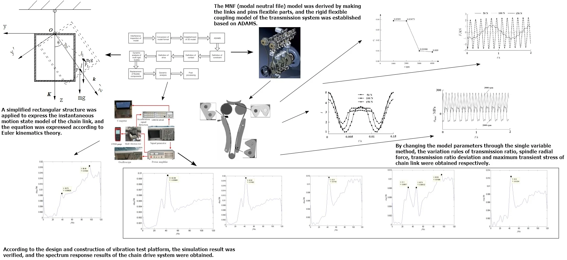
- A simplified rectangular structure was applied to express the instantaneous motion state model of the chain link, and the equation was expressed according to Euler kinematics theory.
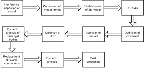
- The MNF (modal neutral file) model was derived by making the links and pins flexible parts, and the rigid flexible coupling model of the transmission system was established based on ADAMS.
- Since invalid constraints were adjusted and replaced, the transmission system model was simulated and calculated precisely.
1. Introduction
Excessive or abnormal vibration can directly affect the reliability and safety of marine engine. As the core component of marine engine, the transmission system is also one of the most important excitation source for the whole machine vibration. The vibration of the engine transmission system would be transmitted to the engine casing through the support structure, thus affecting the vibration of the whole machine. At present, dual rotor engine has been more and more widely used in ship drive, which can provide higher work efficiency per unit time. However, due to the coupling of structures, the vibration characteristics of transmission system are more complex. In order to improve the service life, most marine dual rotor engines adopt gear chain transmission [1]. However, the contact surface of the transmission structure during meshing is polygonal, which inevitably causes chain fluctuation because of polygonal effect [2]. In addition, the meshing impact between the chain plate and the sprocket and other factors will lead to different degrees of vibration and noise of the chain system. At present, the research on the transmission system is mainly based on the multi rigid body dynamics method, such as: Chen [3] established a single degree of freedom multi rigid body dynamic model of the motor main transmission system, solved its differential equations of motion by numerical methods, and obtained the laws of the angular velocity of the motor and the output velocity of steady-state motion; Hua [4] simulated and analyzed the vibration characteristics of spiral bevel gear transmission, and obtained the effect of gear shaft on vibration through structural transformation; conducted dynamic simulation analysis on the transmission structure of a cable car, Tarichko [5] established a rigid dynamic differential equation, and verified the simulation results with experimental tests; Balakin [6] established Appell equation for the transmission mechanism of the reducer to study the influence of different gear structures on dynamic characteristics.
However, in some cases, the flexible deformation of the transmission structure cannot be directly ignored, which has an important impact on the dynamic characteristics, so it is difficult for the rigid body model to meet the accuracy requirements. Modal characteristic is also one of the most important research directions of marine engine. If the results of modal analysis are applied to the study of dynamic response of rigid body model, the calculation accuracy can be effectively ensured. In this paper, a rigid flexible coupling dynamic model for marine dual rotor engine transmission system is established. Based on this model, the influence of working parameters on output response can be studied more accurately, including tension, rotational speed and the number of sprocket teeth. At the same time, combined with the test, the influence law of the transmission system on the vibration of the whole engine is obtained.
2. Establishment of dynamic model of transmission system
2.1. Equation of motion state of single chain drive
The centroid and posture state are the key factors that affect the vibration of chain drive. Therefore, regardless of the chain shape, a simplified rectangular structure is used to express the instantaneous motion state model of the chain link, as shown in Fig. 1. It can be seen that the position of the center of mass is point P in the plane. Three independent coordinate variables are required to describe the motion of a rigid body rotating around a relative fixed point in three-dimensional space. In order to describe its instantaneous state more conveniently, the planar motion of the link around the point can be decomposed into three independent axial rotations through coordinate transformation, that is, Euler angle (precession angle , Nutation angle and self-rotation angle ). According to Euler kinematics theory (gyro theory), the components of angular velocity in the three directions of the fixed coordinate system are , and . Its coordinate transformation expression [7] is:
In the Lagrange Poisson case, the gravity moment of the gyroscope is , then the gravity moment of the gyroscope is:
where is the unit vector of -axis in static coordinate system, and can be expressed as:
where , and are the unit vectors of , and respectively in the moving coordinate system. Therefore, the gravity moment is expressed as:
Due to assembly interference, design error, polygon effect and other reasons, the timing toothed chain system is easy to fluctuate during operation. Therefore, the kinematics characteristics can be studied through multi-body dynamics analysis to judge whether the system can work smoothly. The flow of multi-body dynamics analysis designed in this paper is shown in Fig. 2. It can be seen that the chain drive mechanism is the key component and bearing unit of the entire transmission system, and its dynamic characteristics need to be accurately studied. Among them, the layout parameters can be obtained, and the modeling software Solidworks is used to model and assemble the components as in Fig. 2(b).
Fig. 1The motion state of a single link
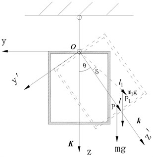
Fig. 2Dynamic modeling and analysis process
a) Main principles and processes of simulation
b) Overall structure of engine transmission system
2.2. Rigid model settings
The main components of the transmission system and their assembly forms are shown in Fig. 3. After the virtual prototype model is established, the final assembly needs to be checked for interference. This is because assembly interference will seriously affect the accuracy of some dynamic characteristic parameters, and contact errors can lead to simulation failure. Use the check function of SolidWorks software to check the interference of the assembly. After all the preceding steps are completed, the model format can be converted into the general STP format and input into the dynamic simulation software ADAMS for analysis. Before simulation and calculation, the boundary conditions used in the chain drive system model should be defined, mainly including constraints, contact and driving loads. According to the analysis of the motion form of the system, the chain system rotates clockwise during normal operation. Therefore, the left chain is loose and the right chain is tight. The loose side needs to be equipped with a tensioning guide rail to apply the tensioning force, and the tight side only needs to be equipped with a fixed guide rail for guidance.
Fig. 3Rigid body model of transmission system
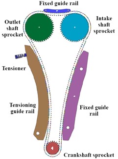
a) Model assembly structure
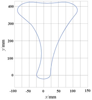
b) Initial trajectory of chain
In order to study the motion of the chain system on the two-dimensional plane, it is necessary to impose constraints on all chain plates and pin shafts to ensure their motion on the same plane. At the same time, the crankshaft sprocket and the two camshaft sprockets are applied with rotating pairs to rotate around the shafts. A fixing pair is added to the fixed guide rail to ensure that it will not move due to friction with the chain plate. The tensioner is applied with spring force, and a rotating pair is applied to the tensioning guide rail to ensure that the guide rail can rotate around the rotation axis under the action of tensioner, so as to apply tension to the side. During the normal operation of the chain system, there is contact between the chain plate and the pin shaft, between the chain plate and each sprocket, between the chain plate and each guide rail, between the tensioner and the tensioning guide rail, and contact pairs are applied between the above contact parts. The chain system does not have a certain initial speed at the beginning of operation, but accelerates from zero to the specified speed, so a certain acceleration time should be set. The driving load function adopts step function. For the coordinate transformation processing of simulation analysis, the kinematics calculation of rigid body components is mainly based on Eq. (1), and the dynamics calculation is based on Eq. (4).
2.3. Establishment of rigid flexible coupling model
For rigid flexible coupling analysis, there are mainly two modeling methods: modal flexible body (modal reduction technology) and finite element flexible body (fully flexible body technology). Modal flexible body is closely linked with finite element modal analysis technology. It can ignore relatively small deformation modes, so as to accurately describe the dynamic characteristics of the system with less degrees of freedom and reduce the solution scale, improve the calculation efficiency, and is mostly used to analyze structures with relatively small deformation. Different from modal flexible body, finite element flexible body uses relative displacement and rotation between nodes to describe deformation [8], which increases the solution scale and reduces the solution efficiency, but also obtains high calculation accuracy, and it does not need to use finite element tools to solve the flexible body. Compared with multi-body dynamic analysis of pure rigid body, rigid flexible coupling analysis converts rigid body into flexible body through grid division, and divides it into finite elements to solve respectively. The solution mainly includes stress and deformation. Because the contact, constraint, degree of freedom and other problems contained in the chain system are too complex, the calculation is slow, and the use of finite element flexible body itself will affect the calculation speed, resulting in too long calculation time and high trial and error cost. The flexible components and connection surfaces are shown in Fig. 4(a). It can be seen that the rigid and flexible contact surfaces are the side surface of the chain link and the end surface of the pin respectively.
Fig. 4Rigid flexible coupling model of transmission system
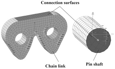
a) Flexible components and connection surfaces
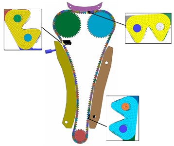
b) Coupled assembly model
The main purpose of the rigid flexible coupling analysis is to study the instantaneous stress state during the movement of the system, and the displacement of the chain in the axial direction of the sprocket is not considered in the analysis. For more efficient analysis, the chain system model can be simplified to a certain extent. By reducing the number of components in the system as much as possible and retaining only necessary components, the purpose of reducing contact pairs and shortening calculation time can be achieved. Rigid flexible coupling of the model mainly refers to the transformation of flexible bodies in Adams environment, that is, the rigid body of the chain is replaced with the previously generated modal neutral file. In order to ensure the accuracy of structural analysis, “align flex body cm with cm of current part” should be set, that is, the centroids of the two should coincide. The rigid flexible coupled model will have out of date constraints, so further constraint setting is required. The chain elements are discretized into fine grids, and the modal neutral file (MNF) can be obtained through modal calculation, that is, the flexibility of the chain link model can be realized. The MNF file contains the quality attributes and modal characteristics of the target model. The mesh elements share a node to transfer the force, and the internal stress and strain of the element can be calculated through the properties of the material. Through coordinate matching, the rigid flexible coupling model is finally obtained, as shown in Fig. 4(b).
3. Analysis of dynamic output response of transmission system
3.1. Influence of tension load on output characteristic
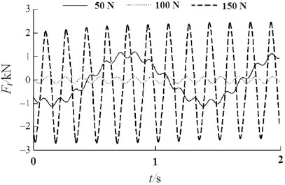
During the operation of the chain system, there will be certain contact between the chain plate and the sprocket, and between the chain plate and the guide rail, which leads to friction and meshing impact. All of these factors will affect the analysis results of dynamic characteristics, resulting in transmission errors of the chain system. Tension is one of the most critical factors affecting this effect [9]. During the operation of marine engine, the transmission ratio between crankshaft sprocket and camshaft sprocket is always stable and accurate. Therefore, the transient transmission ratio can be used to verify the stability of the system. Through the simulation calculation of the rigid flexible coupling model, the transient transmission ratio under different tension conditions can be obtained, as shown in Fig. 5. It can be seen that the tension does not change the change trend of the transmission ratio, but it will affect the specific value. When the tension is 100 N, more stable transmission performance can be obtained. During the normal operation of the chain system, the right tight side chain and the upper cross part chain are guided by the fixed guide rail. Its degree of freedom constraint is more sufficient than the left loose edge, so there will be no obvious fluctuation. In the loose side, the chain plate meshes out of the crankshaft sprocket and is most likely to fluctuate at the point where it will contact with the tensioning guide rail. The radial force of the output shaft of the sprocket is shown in Fig. 6, which can reflect the excitation force effect of the chain. It can be seen that the increase of the tension does not change the vibration response frequency. If the tension is too large or too small, the stability of the output force will deteriorate.
Fig. 5Change of transient transmission ratio
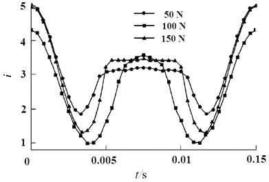
Fig. 6Radial force change of output shaft
3.2. Influence of rotating speed on motion state
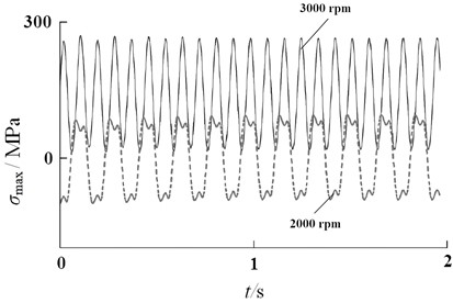
Under the tension of 100 N, the maximum value of the calculated transmission ratio error under different spindle rotation speed is shown in Fig. 7. It can be seen that the value gradually decreases with the rotation speed from low to high, and reaches the maximum at 1000 rpm, which is 0.039. At 6000 rpm, the error value is the smallest, with a value of 0.009. The error value under different rotational speeds does not exceed the standard value of 0.05, which indicates that the transmission ratio is accurate. The maximum stress response results of flexible link parts are shown in Fig. 8. It can be seen from the figure that the influence of rotational speed on stress is very critical. When the rotation speed is 2000 rpm, the stress on the chain link shows obvious periodicity, and the value is small. When the rotation speed increases to 3000 rpm, the maximum stress increases sharply, resulting in more instability. From the perspective of distribution, the stress concentration appears at the top of the crotch of the chain plate, and the stress around the contact surface between the chain plate and the pin is also large.
Fig. 7Change of transmission ratio error
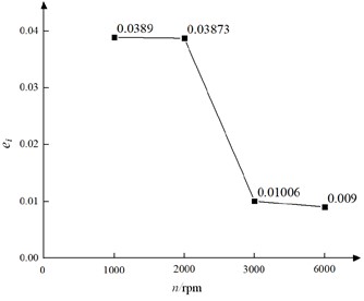
Fig. 8Change of maximum stress of chain link
3.3. Influence of driving sprocket teeth number on link amplitude
The teeth number of driving sprocket is the key factor that affects angular velocity and meshing smoothness of the chain plate. In order to analyze the vibration effect conveniently, the amplitude is symmetrically adjusted through the overall adjustment of the data. Therefore, under the condition that the teeth number is 25 and 30 respectively, the change rule of the chain link amplitude can be obtained, as shown in Fig. 9. It can be seen that the increase of the number of sprocket teeth can significantly reduce the vibration amplitude, but also increase the excitation frequency.
Fig. 9The variation law of chain link amplitude under different number of sprocket teeth
a) 25 sprocket teeth
b) 30 sprocket teeth
The angular velocity of the chain plate is an important measure of the stability of the chain system. Theoretically, when the chain plate meshes with the sprocket, the chain plate rotates with the wheel, and the theoretical value of its angular velocity should be the same as that of the sprocket. When the chain plate contacts the guide rail, its movement form is a combination of movement and rotation. However, most chain drive systems will be affected by various adverse factors, mainly polygonal effect, when they are in operation. Therefore, in each contact stage of the chain system, the angular velocity of the chain plate will fluctuate to different degrees. The stability of the chain system can be verified by studying the fluctuation of the vibration amplitude. However, under specific transmission ratio requirements, the larger the number of teeth, the larger the size of sprocket and transmission system. In addition, this will lead to increased wear of chain links, which is not conducive to the improvement of working life. According to the response frequency, it can be seen that too many teeth will affect the chain drive to jump teeth and fall off the chain earlier. After the chain works for a period of time, the wear makes the pin shaft thinner and the sleeve and roller thinner. Under the action of tensile load, the pitch of the chain is elongated, which requires greater tension.
4. Test and research on dynamic characteristics
4.1. Test scheme design
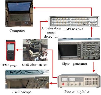
The test system mainly includes computer, engine, transmission system, signal generator, power amplifier, oscilloscope, LMS multichannel vibration, noise data acquisition instrument (LMS SCADAS), and UT320 thermometer, etc. the test device is shown in Fig. 10. In Fig. 10, all the photos were taken by the author in the dynamic analysis and testing laboratory before the test. The power amplifier can effectively amplify the signal and output effective voltage signal power [10]. Oscilloscope measurement is mainly used to measure the amplified voltage signal of the amplifier, so the amplified control voltage signal can be input to the engine control terminal when the power amplifier is working. The accelerometer is used to measure the vibration acceleration signal at the engine connection. LMS multi-channel vibration and noise data acquisition instrument is used to process the collected acceleration signals [11]. UT320 thermometer is mainly used to measure the surface temperature of the engine to avoid failure data. The acceleration sensor is set and installed according to the coordinate direction, and the signal integration and filter processing are carried out through LMS equipment. Since the detection mode of the sensor is fixed constraint, it is installed on the tensioner surface of the chain transmission system. In the research of experimental verification, the signal sampling frequency is set as 300 Hz, the engine speed range is set as 0-5000 r/min, and the acquisition time is set as 30 s.
Fig. 10Composition of dynamic test system
4.2. Verification of simulation results of chain drive system
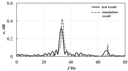
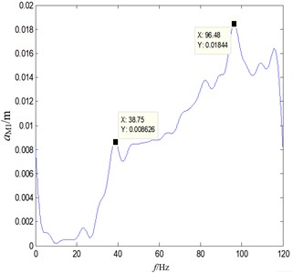
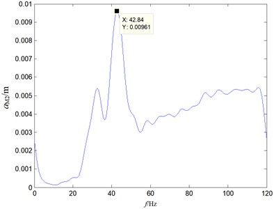
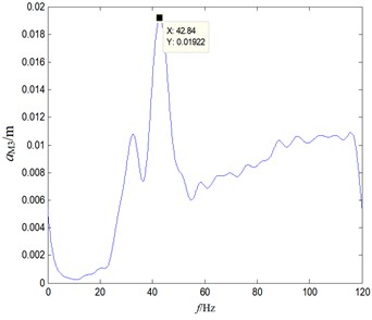
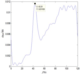
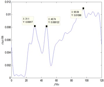
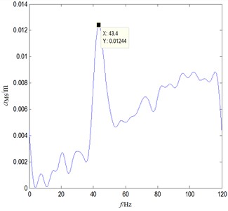
For most mechanical systems, the frequency response mainly refers to the response function of some dynamic parameters to frequency-domain excitation. Frequency response analysis is a common method in the field of engineering applications [12]. It is usually used to analyze the dynamic response of mechanical systems to the excitation frequency under the action of periodic excitation [13]. The amplitude and phase of the response can generally be obtained through calculation. In order to eliminate the phase deviation difference in the test, the relative amplitude is used as the verification standard, and its expression is shown in Eq. (5). The signal obtained directly has poor smoothness, which is not conducive to comparative analysis. In order to better display the changing rule of the spectrum curve, the signal was filtered and smoothed through the program in the detection system. The dynamic response of the chain drive system is compared and analyzed through the spectrum test results, as shown in Fig. 11. It can be seen that the simulation results are in good agreement with the experimental results. Not only the peaks correspond to each other, but also the natural frequencies have a small difference. It can also be proved that the rigid flexible coupling model of the transmission system can achieve good dynamic characteristic analysis accuracy. Two typical resonance frequencies exist in the chain drive system, and the external excitation frequency should be avoided quickly to prevent the vibration from aggravating:
where is the transient amplitude, is the reference amplitude at time 0, so as to ensure that the initial relative amplitude of the spectral response is 0.
Fig. 11Spectrum response result of the chain drive system
4.3. Measurement of vibration transmission characteristics
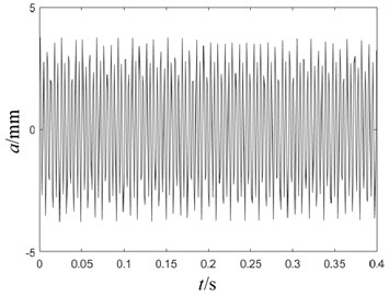
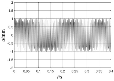
Under the condition that the tension is 50 N and 100 N respectively, the external vibration spectrum caused by the chain drive can be obtained, as shown in Fig. 12. It can be seen that the effect of tension on the natural frequency is very small, but the effect on the vibration amplitude is very significant, which is consistent with the simulation results. When the tension is set to 100 N, the amplitude of low-frequency vibration of the chain transmission system is significantly reduced, and the stability of high-frequency vibration is better. In addition, the maximum amplitude is reduced by 47.8 % due to the vibration cancellation of adjacent structures. It can be known that the excitation frequency should also be considered in the selection of tensioning force, otherwise it is difficult to obtain effective damping effect.
Fig. 12Spectrum response under different tension
a) Tension of 50 N
b) Tension of 100 N
Rotational speed is the key factor affecting the input of excitation frequency. Under the condition that the main shaft maximum rotational speed is 3000 rpm and 2000 rpm respectively, the external vibration spectrum caused by the chain drive can be obtained, as shown in Fig. 13. It can be seen that because the excitation frequency will change the flexible characteristics of the chain, it has a slight impact on the natural frequency. However, the effect on amplitude is very significant. Compared with 3000 rpm condition, 2000 rpm condition can reduce the maximum amplitude by 39.6 %.
Keeping the test parameters unchanged, under the condition that the number of sprocket teeth is 25 and 30 respectively, the response results to vibration can be obtained, as shown in Fig. 14. It can be seen that the number of sprocket teeth has a more significant impact on low-frequency vibration. When the excitation frequency exceeds 60 Hz, the influence of the number of sprocket teeth on the vibration is weakened. As the number of teeth increases, the characteristic frequency of resonance will also increase, so certain unstable factors will appear. It can also be seen that the number of teeth should be reasonably selected, and too much or too little will have a bad impact on the system. Combined with the simulation results shown in Fig. 9, it can be seen that the number sprocket teeth is critical to the vibration response of the chain link and even the entire transmission system. Therefore, the optimization of the number of teeth can be an effective factor to reduce vibration and noise.
Fig. 13Spectral response at different rotational speeds
a) Rotational speed of 3000 rpm
b) Rotational speed of 2000 rpm
Fig. 14Spectrum response of different sprocket teeth
a) 25 sprocket teeth
b) 30 sprocket teeth
5. Conclusions
The vibration problem of marine engine transmission system is an important engineering problem, which has an important impact on the performance, working life and stability of the whole drive system. According to the structural characteristics of marine dual rotor engine transmission system, a theoretical model and a rigid flexible coupling simulation model are established. Combined with numerical simulation and experimental testing, the influence of key operating parameters on vibration response can be obtained. The main conclusions are as follows:
1) The rigid flexible coupling model has a good application effect in the dynamic analysis of the transmission system, and can effectively ensure the calculation accuracy of the vibration response. Because the chain belongs to a typical elastic moving part, and the polygon effect is significant, the model can be imported into the general assembly model in the form of MNF file, which can obtain high simulation efficiency.
2) Through rigid flexible coupling simulation, the time domain variation laws of instantaneous transmission ratio, radial force of main shaft, maximum stress and amplitude of chain plate are obtained. According to the dynamic testing system, the frequency spectrum response characteristics under different tension, rotating speed and sprocket tooth number are obtained. These results can effectively reflect the stability of the transmission system. The simulation and test results show that the tension, the rotation speed of the main shaft and the number of driving sprocket teeth have a very significant impact on the vibration of the transmission system. The optimal tension value range is about 100 N. If the tension is too large or too small, the stability of the output force and transmission ratio will deteriorate. When the output rotation speed of the spindle is 2000 rpm, the maximum amplitude can be reduced by about 40 %, compared with 3000 rpm condition. The number of sprocket teeth can affect the polygon effect, so it has a key impact on the frequency response, especially the low-frequency vibration. The research method and conclusion can provide an important basis for the structure and performance optimization of the transmission system.
References
-
A. Serebrennikov and V. Kuzmichev, “Design calculations for vibration mixer chain drive,” in IOP Conference Series: Materials Science and Engineering, Vol. 327, No. 4, p. 042098, Mar. 2018, https://doi.org/10.1088/1757-899x/327/4/042098
-
S. B. Berezhnoi, S. A. Metil’Kov, and A. A. Skoryunov, “Transverse vibrations of a leading strand in special chain drives functioning in the machinery and equipment of an oil and gas complex,” Chemical and Petroleum Engineering, Vol. 50, No. 7-8, pp. 536–541, Nov. 2014, https://doi.org/10.1007/s10556-014-9937-3
-
Y. Chen, “Dynamic analysis of mechanical transmission system to realize constant speed reciprocating motion,” (in Chinese), Mechanical Design, Vol. 39, No. 1, pp. 98–104, 2022, https://doi.org/10.13841/j.cnki.jxsj
-
X. Hua, S. Qiang, and W. Hang, “Influence of gear-shaft-bearing configurations on vibration characteristics of spiral bevel gear drives,” SAE International Journal of Vehicle Dynamics, Stability, and NVH, Vol. 4, No. 3, pp. 19–24, Jun. 2020, https://doi.org/10.4271/10-04-03-0019
-
V. I. Tarichko and I. A. Lagerev, “Dynamics simulation and experimental analysis of a mobile cable car base station’s mechanical transmissions,” Nauchno-Tekhnicheskiy Vestnik Bryanskogo Gosudarstvennogo Universiteta, Vol. 6, No. 2, pp. 318–326, Jun. 2020, https://doi.org/10.22281/2413-9920-2020-06-02-318-326
-
P. D. Balakin, O. S. Dyundik, and I. P. Zgonnik, “Dynamic model of the mechanical drive with automatic continuously variable transmission on the basis of Appell’s equations,” Journal of Physics: Conference Series, Vol. 1441, No. 1, p. 012085, Jan. 2020, https://doi.org/10.1088/1742-6596/1441/1/012085
-
Y. Zhang, S. M. Wang, and Q. Wang, “Analysis of the independence of Euler angle and coordinate transformation matrix of a rigid body moving at a fixed point,” (in Chinese), Mechanics and Practice, Vol. 44, No. 2, pp. 385–389, 2022.
-
Z. Fan, C. Zhu, and C. Song, “Dynamic analysis of planetary gear transmission system considering the flexibility of internal ring gear,” Iranian Journal of Science and Technology, Transactions of Mechanical Engineering, Vol. 44, No. 3, pp. 695–706, Sep. 2020, https://doi.org/10.1007/s40997-019-00290-3
-
A. B. Somochkin, V. O. Fedotov, and D. O. Kalmus, “Research of dynamics of the systems of electric drive for mine electric locomotives in the conditions of iron-ore enterprises,” Microsystems, Electronics and Acoustics, Vol. 23, No. 3, pp. 25–29, Jun. 2018, https://doi.org/10.20535/2523-4455.2018.23.3.132148
-
J. Tan, D. Shi, D. Huang, and J. Gu, “Test and analysis of three axis vibration of harmonic drives,” Vibroengineering PROCEDIA, Vol. 16, pp. 19–24, Dec. 2017, https://doi.org/10.21595/vp.2017.19378
-
W. Xia, H. Wang, Q. Lu, Y. Tan, and P. Zhao, “Study on the effectiveness test of bacterial activity in the antibacterial property vibration test of antibacterial textiles,” Journal of Biobased Materials and Bioenergy, Vol. 13, No. 1, pp. 140–143, Feb. 2019, https://doi.org/10.1166/jbmb.2019.1810
-
K. Mizuno, M. Tanaka, M. Ogata, and T. Okamura, “Mechanical vibration test of a REBCO coil designed for application to the maglev,” IEEE Transactions on Applied Superconductivity, Vol. 28, No. 4, pp. 1–7, Jun. 2018, https://doi.org/10.1109/tasc.2018.2816098
-
L. A. Spreij, A. F. Ten Brink, J. M. A. Visser-Meily, and T. C. W. Nijboer, “Increasing cognitive demand in assessments of visuo-spatial neglect: Testing the concepts of static and dynamic tests,” Journal of Clinical and Experimental Neuropsychology, Vol. 42, No. 7, pp. 675–689, Aug. 2020, https://doi.org/10.1080/13803395.2020.1798881
About this article

The paper is supported by provincial scientific research projects (62874136).
The datasets generated during and/or analyzed during the current study are available from the corresponding author on reasonable request.
The authors declare that they have no conflict of interest.
